Ive played around with different versions for years, results vary with the design features and how well the systems thought thru and built, but correctly designed they do get impressive results, badly designed they can hurt performance.
exhaust systems are frequently thought of by many guys as a way to route hot/burnt gases away from the engine and a way to reduce the engine noise, its fairly common for guys to either just slap on a set of headers that are listed as fitting the car the guys using without much thought or if anything is thought thru its simply to look for a low restriction muffler.
keep in mind your cam timing, intake runner design,displacement,compression, and other factors help or hinder the results you'll get.
those hot exhaust gases exit under hundreds of psi of pressure and potentially have a great deal of inertia that can be used to help increase the negative cylinder pressure and significantly increase the intake runner flow rates as flow out thru the properly tuned exhaust header drags in the next intake runner charge during the valve overlap period.
low and mid rpm torque increases are common in a well designed set of AR headers,high rpm power loss is common in badly designed headers
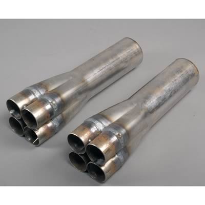
for those that don,t know what were referring to its headers/exhaust designed to flow only in one direction, baffles are designed into the primary and collectors to break up or retard reversion pulses.
your goal is to keep the exhaust speed/energy high to maximize cylinder scavenging yet restriction low to reduce back pressure to the minimum and to control and direct reversion pulse energy to assist in that scavenging.
the properly tuned set of headers matched to a low restriction exhaust and especially if your using a single runner per cylinder stack type injection can , with a correctly timed cam, give amazing results, gains of 40-70 ft lbs or even higher levels of torque can result from tuning both the exhaust and intake runners and cam timing, on a race V8 with high compression and properly tuned components are very common, over and above what a typical single carburetor intake can produce.
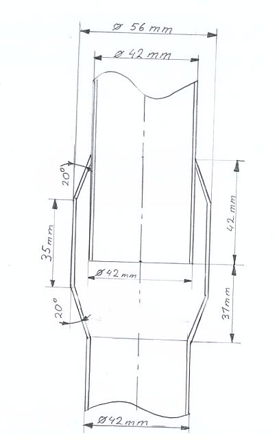
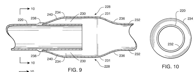
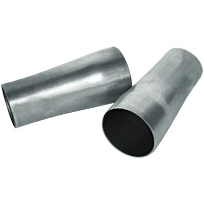
generally its done by extending the primary header tubes at some point into a larger primary tube (stepping up, so as to leave a sharp edge that the reversion pulse generated at some rpm ranges has difficulty traveling back over. or installing venturis (tapered cones) in the exhaust headers that accomplish the same effect or BOTH
yes you really do need to read thru the links, and sub linked info
http://garage.grumpysperformance.com/index.php?threads/building-custom-headers.961/
http://www.headerdesign.com/extras/design.asp
viewtopic.php?f=38&t=1002&p=1805&hilit=+curve#p1805
http://www.burnsstainless.com/Xdesign/xdesign.html
viewtopic.php?f=55&t=4502
http://www.vetteguru.com/mods/headers/
http://www.boatheaders.com/reversionbody.htm
http://www.burnsstainless.com/dynosys/dynosys.html
http://www.headersbyed.com/bildbetr.htm
http://victorylibrary.com/mopar/header-tech-c.htm
viewtopic.php?f=38&t=1002&p=1805#p1805
http://www.headersbyed.com/stepped.htm
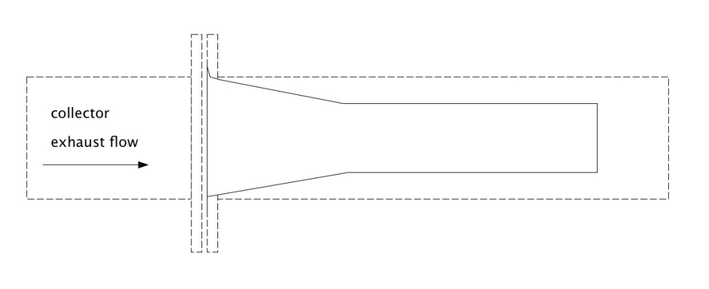
as a simple example of a mod that usually gets results if the reduction is smooth/gradual, if its fairly abrupt the reduction acts as a restriction or even causes reversion to some extent
install one of these venturies in the 3" exhaust pipe(small end toward the rear)where the 3" collector mates to the 3" exhaust pipe to form a lip or step in the exhaust so any reversion pulse tends to have difficulty traveling from the exhaust to the collector
adding an (X) just past the anti reversion venturies reduces or at least tends to reduce reversion pulse strength also
adding an anti-reversion baffle to a 18"-24" longer collector on open headers with the internal pipe about 1/2 the collector length tends to help scavenging on some engines, no header will function to full efficiency with any significant back pressure so take the effort to accurately measure any restriction to exhaust flow AT your upper rpm range of your engines power band and be darn sure its not choking your power curve.
one of the reasons I own a MILLER 330 amp TIG welder, and a 250 amp mig welder,
is the frequent need to fabricate and modify components,
and the exhaust system is a frequent area modified
http://www.wallaceracing.com/intake-runner-length.php
http://www.bgsoflex.com/intakeln.html
http://www.velocity-of-sound.com/velocity_of_sound/calculator3.htm
http://www.velocity-of-sound.com/velocity_of_sound/velocity_stacks.htm
http://www.swartzracingmanifolds.com/tech/index.htm
http://www.summitracing.com/search/?keyword=exhaust cones&dds=1
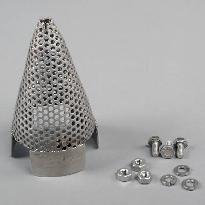
IF your trying to reduce noise levels, you can buy or fabricate these cones that tend to break up and reduce exhaust noise, once installed in the exhaust, without producing much of a restriction since the total surface area of the mini holes is greater the the pipes cross sectional area
the tabs can be tack welded or sheet metal screw attached, and adding an (X) pipe near the collectors and an additional (H) near the muffler entrance point tends to mellow the tone
exhaust systems are frequently thought of by many guys as a way to route hot/burnt gases away from the engine and a way to reduce the engine noise, its fairly common for guys to either just slap on a set of headers that are listed as fitting the car the guys using without much thought or if anything is thought thru its simply to look for a low restriction muffler.
keep in mind your cam timing, intake runner design,displacement,compression, and other factors help or hinder the results you'll get.
those hot exhaust gases exit under hundreds of psi of pressure and potentially have a great deal of inertia that can be used to help increase the negative cylinder pressure and significantly increase the intake runner flow rates as flow out thru the properly tuned exhaust header drags in the next intake runner charge during the valve overlap period.
low and mid rpm torque increases are common in a well designed set of AR headers,high rpm power loss is common in badly designed headers
for those that don,t know what were referring to its headers/exhaust designed to flow only in one direction, baffles are designed into the primary and collectors to break up or retard reversion pulses.
your goal is to keep the exhaust speed/energy high to maximize cylinder scavenging yet restriction low to reduce back pressure to the minimum and to control and direct reversion pulse energy to assist in that scavenging.
the properly tuned set of headers matched to a low restriction exhaust and especially if your using a single runner per cylinder stack type injection can , with a correctly timed cam, give amazing results, gains of 40-70 ft lbs or even higher levels of torque can result from tuning both the exhaust and intake runners and cam timing, on a race V8 with high compression and properly tuned components are very common, over and above what a typical single carburetor intake can produce.
generally its done by extending the primary header tubes at some point into a larger primary tube (stepping up, so as to leave a sharp edge that the reversion pulse generated at some rpm ranges has difficulty traveling back over. or installing venturis (tapered cones) in the exhaust headers that accomplish the same effect or BOTH
yes you really do need to read thru the links, and sub linked info
http://garage.grumpysperformance.com/index.php?threads/building-custom-headers.961/
http://www.headerdesign.com/extras/design.asp
viewtopic.php?f=38&t=1002&p=1805&hilit=+curve#p1805
http://www.burnsstainless.com/Xdesign/xdesign.html
viewtopic.php?f=55&t=4502
http://www.vetteguru.com/mods/headers/
http://www.boatheaders.com/reversionbody.htm
http://www.burnsstainless.com/dynosys/dynosys.html
http://www.headersbyed.com/bildbetr.htm
http://victorylibrary.com/mopar/header-tech-c.htm
viewtopic.php?f=38&t=1002&p=1805#p1805
http://www.headersbyed.com/stepped.htm
as a simple example of a mod that usually gets results if the reduction is smooth/gradual, if its fairly abrupt the reduction acts as a restriction or even causes reversion to some extent
install one of these venturies in the 3" exhaust pipe(small end toward the rear)where the 3" collector mates to the 3" exhaust pipe to form a lip or step in the exhaust so any reversion pulse tends to have difficulty traveling from the exhaust to the collector
adding an (X) just past the anti reversion venturies reduces or at least tends to reduce reversion pulse strength also
adding an anti-reversion baffle to a 18"-24" longer collector on open headers with the internal pipe about 1/2 the collector length tends to help scavenging on some engines, no header will function to full efficiency with any significant back pressure so take the effort to accurately measure any restriction to exhaust flow AT your upper rpm range of your engines power band and be darn sure its not choking your power curve.
one of the reasons I own a MILLER 330 amp TIG welder, and a 250 amp mig welder,
is the frequent need to fabricate and modify components,
and the exhaust system is a frequent area modified
http://www.wallaceracing.com/intake-runner-length.php
http://www.bgsoflex.com/intakeln.html
http://www.velocity-of-sound.com/velocity_of_sound/calculator3.htm
http://www.velocity-of-sound.com/velocity_of_sound/velocity_stacks.htm
http://www.swartzracingmanifolds.com/tech/index.htm
http://www.summitracing.com/search/?keyword=exhaust cones&dds=1
IF your trying to reduce noise levels, you can buy or fabricate these cones that tend to break up and reduce exhaust noise, once installed in the exhaust, without producing much of a restriction since the total surface area of the mini holes is greater the the pipes cross sectional area
the tabs can be tack welded or sheet metal screw attached, and adding an (X) pipe near the collectors and an additional (H) near the muffler entrance point tends to mellow the tone
Last edited by a moderator: