You are using an out of date browser. It may not display this or other websites correctly.
You should upgrade or use an alternative browser.
You should upgrade or use an alternative browser.
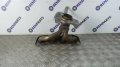
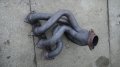
240 Deg Timed Tri Y Headers
- Thread starter Stewart Battersby
- Start date

yes I had built and used a similar custom designed, or lets say extensively modified set, on my 1965 Pontiac le mans with a 496 BBC engine
they worked great!
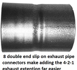
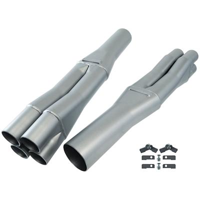
the fast route is to buy these and carefully measure cut old headers
and weld them on but due to the restricted clearances you are generally better off visiting a muffler shop and having them fabricate 8 short sections of expanded exhaust tube (they may need to be angled first) with both ends of a 2"-4" long length expanded to slide over each primary tube in the cut header and extension, obviously careful measurement is critical here
https://www.summitracing.com/parts/flo-c178238300
reading the links and sub-links will certainly help
http://garage.grumpysperformance.com/index.php?threads/building-custom-headers.961/
http://garage.grumpysperformance.com/index.php?threads/exhaust-h-pipe-leading-into-a-x-pipe.15118/
http://garage.grumpysperformance.co...-guys-that-just-slap-on-factory-headers.3155/
http://garage.grumpysperformance.com/index.php?threads/header-dimension-calculator.15013/#post-84900
http://garage.grumpysperformance.com/index.php?threads/calculating-required-exhaust-pipe-size.11552/
http://garage.grumpysperformance.com/index.php?threads/building-an-exhaust-system-for-your-car.1166/
https://www.onallcylinders.com/2015...-at-the-science-behind-exhaust-header-tuning/
https://www.onallcylinders.com/2015...ng-header-collectors-for-optimum-performance/
https://www.centuryperformance.com/exhaust-header-tube-sizing-and-length.html
https://www.musclecardiy.com/perfor...t-system-math-build-high-performance-engines/
http://www.bgsoflex.com/bestheader.html
http://www.mezporting.com/exhaust_length.html
http://www.wallaceracing.com/header_length.php
they worked great!
the fast route is to buy these and carefully measure cut old headers
and weld them on but due to the restricted clearances you are generally better off visiting a muffler shop and having them fabricate 8 short sections of expanded exhaust tube (they may need to be angled first) with both ends of a 2"-4" long length expanded to slide over each primary tube in the cut header and extension, obviously careful measurement is critical here
https://www.summitracing.com/parts/flo-c178238300
reading the links and sub-links will certainly help
http://garage.grumpysperformance.com/index.php?threads/building-custom-headers.961/
http://garage.grumpysperformance.com/index.php?threads/exhaust-h-pipe-leading-into-a-x-pipe.15118/
http://garage.grumpysperformance.co...-guys-that-just-slap-on-factory-headers.3155/
http://garage.grumpysperformance.com/index.php?threads/header-dimension-calculator.15013/#post-84900
http://garage.grumpysperformance.com/index.php?threads/calculating-required-exhaust-pipe-size.11552/
http://garage.grumpysperformance.com/index.php?threads/building-an-exhaust-system-for-your-car.1166/
https://www.onallcylinders.com/2015...-at-the-science-behind-exhaust-header-tuning/
https://www.onallcylinders.com/2015...ng-header-collectors-for-optimum-performance/
https://www.centuryperformance.com/exhaust-header-tube-sizing-and-length.html
https://www.musclecardiy.com/perfor...t-system-math-build-high-performance-engines/
http://www.bgsoflex.com/bestheader.html
http://www.mezporting.com/exhaust_length.html
http://www.wallaceracing.com/header_length.php
Last edited:
Stewart Battersby
Member
Cool. So, mathematically it makes sense to me as I like to run between 224 and 255 deg at 0.050” exhaust timing. I use VE at my designed torque for target HP. To size pipe lengths. How did the big engine sound, Grumpy?
I've always wanted to design my own headers, I just like to do my own thing .... right or wrong,
it's a learning process. I bought Dynomation 6 so I could do this, but it is alot of work, I would
need to know internal intake dimensions to begin with and it does not stop there. I guess what
I'm trying to say is. this will not be a one week project, it might take several between all the
questions and answers, back and forth. I've never done this yet, but if you are willing to get into
the details, then I would like to try this for the first time.
Give it some thought ... maybe some questions and let me know what you think. I understand if
this is just too time consuming and trouble.
Below are the dimensions (for most complicated design, "Tri-Y Two Collectors, with 2-Step
Primary and Megaphone" and at the very bottom is the manual that will explain all the
parameters. Exhaust starts on page 192.

You can download the complete manual below ......
http://www.motionsoftware.com/Dynomation6.htm
.
it's a learning process. I bought Dynomation 6 so I could do this, but it is alot of work, I would
need to know internal intake dimensions to begin with and it does not stop there. I guess what
I'm trying to say is. this will not be a one week project, it might take several between all the
questions and answers, back and forth. I've never done this yet, but if you are willing to get into
the details, then I would like to try this for the first time.
Give it some thought ... maybe some questions and let me know what you think. I understand if
this is just too time consuming and trouble.
Below are the dimensions (for most complicated design, "Tri-Y Two Collectors, with 2-Step
Primary and Megaphone" and at the very bottom is the manual that will explain all the
parameters. Exhaust starts on page 192.
You can download the complete manual below ......
http://www.motionsoftware.com/Dynomation6.htm
.
Stewart Battersby
Member
Yeah. Larry Meaux has the Pipemax which is also superb to use. I have been training myself on the Dynosim 5 for years now. It has woken my thinking and a lot of ( what I thought I had lost) mathematical thinking. I have complete faith in Dynosim 6 and the VE, ignition, BMEP and fuel calculations. Proved them many times over in my little engines on my Prony brake I made. Larry Atherton’s mathematics and his perseverance with his Dynosim software, to me, is other world like, Intelligence. Just awesome. I notice he has affiliation with Comp Cams so I am fluffing about with the Cam Files that came with Dynosim 6 included. In particular the files using low max lift. Lots of thinkin’ goin’ on ferr this Ol’ boy, now!
I found an old 911 workshop manual today. That exhaust manifold for the old 911 is also something I enjoy thinking about. Is it cool to post the flat six, even fire 911 historic system, here?
I found an old 911 workshop manual today. That exhaust manifold for the old 911 is also something I enjoy thinking about. Is it cool to post the flat six, even fire 911 historic system, here?
I don't know why not, go ahead, you are in the right section so no problem.I found an old 911 workshop manual today. That exhaust manifold for the old 911 is also something I enjoy thinking about. Is it cool to post the flat six, even fire 911 historic system, here?
.
Stewart Battersby
Member
I will photograph a few to scale drawings I found for the flat six, soon. I recall seeing tube exhausts on 4 Cyl engines where tubes dumped into a catalytic converters. I measured the pipes which were tuned length for volume of each cylinder, inclusive of the exhaust port. Astra, Renault etc. Enveloped with double insulated shields. No timed pipe merges. I found some mathematics on rpm, speed of sound and piston position, if anyone is interested. It turns out if you can keep the exhaust gas at 800 deg C in your pipes a person can calculate pipe length before collector to get a negative pressure wave to the exhaust valve at BDC.
JohnHancock
Well-Known Member
You guys make my head hurt! Lol
I would like to see it, wondering if it's something that I have not seen yet.I found some mathematics on rpm, speed of sound and piston position, if anyone is interested.
Stewart Battersby
Member
Could you post some of your calcs with a explanation maybe ?I ran through some quick maths yesterday using a 114 LC exhaust. Interesting stuff.
I see the your article refers to a person named Blair, that would be Gordon P Blair. You should buy
his book and then send it to me after you have read it, it's only $121 down from $136 when I
first checked. .....hehehe !!!
https://www.amazon.com/Design-Simul...=design+and+simulation+of+four+stroke+engines
Check out this thread it has several more resources.
http://garage.grumpysperformance.com/index.php?threads/header-dimension-calculator.15013/#post-84900
.
Stewart Battersby
Member
I have the file, man. Yes, Gordon Blair. We are lucky he wrote his understanding down.
I can only get my head around some of it.
I did some work today and photographed the scribbles. I think I can explain it all too.
Shall post my attempts, tomorrow. Thank you for letting me share my thoughts.
I can only get my head around some of it.
I did some work today and photographed the scribbles. I think I can explain it all too.
Shall post my attempts, tomorrow. Thank you for letting me share my thoughts.
That's what this forum is all about !Shall post my attempts, tomorrow. Thank you for letting me share my thoughts.
Stewart Battersby
Member
If I start out thinking that when a sound wave leaves a tube, it creates an equal but negative wave in the tube. I will post the references once we get the chat flowing.
I noticed in the F1 pipe calculations that they were discussing speed of sound and crank degrees for exhaust timing. So I got to thinking if we can create a negative sound wave, that means a negative pressure in the exhaust port. Why not put that pressure right at BDC? Less pumping loss on the upward exhaust stroke, for one part of thinking.
So if Exhaust Temperature is 815 deg C. (Which is pretty darn close to ideal temp for max power on Petrol)
And I know the speed of sound at 815deg C is 661Metres/second.
What a terrific thing to use for my engine build.
250 exhaust duration at 112 lobe centre.
Gives me 56/14 timing at 0.050"
What if I could get that negative wave at BDC?
My target max HP rpm is 6500 rpm. How long for one crank revolution at 65oorpm?
6500rpm/60 seconds = 108.33 revolutions/second.(rps)
So one crank revolution should be 1sec/108.33 rps= 0.00923 seconds.
0.00923 sec= 9.23 milli sec.(ms) = 9230 micro seconds (us)
So: One crank revolution at 6500rpm takes 9230 us.
Stewart Battersby
Member
If that is correct,
What is the Time (t) taken for the crank to travel 1 degree at 6500 rpm?
One crank rotation is 360 deg. (360 deg in a circle)
So Time , t=9230 us.
360 deg in one rotation.
So t/360 deg will give X us per 1 degree.
9230us/360s = 25.638 us per degree, of crank rotation.
T (cd) = Time per 'crank degree' in micro seconds = 25.638 us
T (cd) = 25.638 us.
I have 56 degrees from valve opening. (56 deg BBDC)
So 56 deg x T(cd) = 56deg x 25.638 us = 1435.777 us
Time then during exhaust valve opening from 56 BBDC is 1435.777 us.
.
The current thinking today would want the negative pulse to arrive during overlap, thus helping
pull in more intake charge. If I understand you correctly, you want the negative pulse to arrive at
BDC on the exhaust stroke to help with pumping loses. So you think there is more to be gained by
reducing pumping loses?
I think your number for the speed of sound is too high. Yes it would be 661 m/sec (2168 ft/sec), but
that's at or near the exhaust valve. From there it is cooling off and therefore the speed of sound is
slowing down as the gas gets to the collector where the first negative pulse is reflected back up the
primary tube, assuming a typical 4 into 1 header design. Most estimates that I see for the speed of
sound is around the 1500 ft/sec range, which would be an average over the length of the primary
tube and exhaust port.
https://www.enginelabs.com/news/tech-five-tips-on-building-a-set-of-bad-ass-race-headers/
In a four-stroke engine, as the exhaust valve opens after the power stroke, the cylinder pressure
initiates exhaust blowdown. At this time, a pressure wave traveling the speed of sound
(1,700 feet per second) travels down the exhaust pipe, and as the valve continues to open, the exhaust
gases, moving over 350 feet per second, flow over the valve seat and out the exhaust pipe.
EPG II
https://cafe.foundation/v2/pdf_cafe_reports/EPG2.pdf
.
Last edited:
Stewart Battersby
Member
All good Rick. Just gathering information. On Pipemax and several forums the latest thinking is to close the exhaust early so as not to poison the inlet charge and, reduce inlet charge loss into the exhaust on the overlap. You can see on the LS 1 head for example. A raised area between the valves which is there to reduce inlet loss into the exhaust in the overlap period at TDC, in my humble opinion. If you check some new cam profiles the exhaust is closing earlier eg, lower than 0.050”.
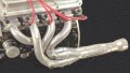
I have been thinking about why the Europeans are using 4 short tubes into a wide open mouthed catalyst chamber, with terrific results in smooth torque and hp from their little 4 and 3 cylinder engines. I think pumping losses and big reductions of inlet charge lost to exhaust is what they are doing.
They seal off the tubes with elaborate encasements of heatshield material , obviously for Catalyst heat stabilisation but, if I look at the design, it could just be, they are tuning exhaust for this new thinking. Another thing that has me interested is , how come Shorty, uneven length headers, connected to a correctly proportioned collector tube, work so damn well through the Torque curve?