connecting rod weights

mtrhead

Member
Do the mfg's advertise their weights with or without bolts? I have a set of 6" h-beams that weigh 715grams with 1.75 long ARP bolts. Without they weight about 645g empty

They look like Scat, Callies, Carillo and others but they dont have the chamfered edge at the bolt end like all of those and they dont have the rib running down the H groove like an Eagle. They do have the dual ribs on the backside and they are coated with a hard smooth coating.
 
mtrhead said:
Do the mfg's advertise their weights with or without bolts? I have a set of 6" h-beams that weigh 715grams with 1.75 long ARP bolts. Without they weight about 645g empty

They look like Scat, Callies, Carillo and others but they dont have the chamfered edge at the bolt end like all of those and they dont have the rib running down the H groove like an Eagle. They do have the dual ribs on the backside and they are coated with a hard smooth coating.
The only weights that I've found is a total weight with bolts included. I have tried to get the weight of each end of the rod for calculating Bob Weights, but Eagle or Scat don't publish that. In fact I email Scat they still would not give me a typical rod end weights.
I found these rod weights for SBC on the Eagle website.

It looks like to me your trying to identify the rods you have, can't help there. If you would post some pictures, then maybe Grumpy could help.

Chevy 350 - Two Piece Seal
part number weight pin size HP rating price
5.700 SIR5700BBLW 560g I-Beam 2.100 0.927 500 265.33
5.700 SIR5700BPLW 565g I-Beam 2.100 0.927 500 238.67
5.700 SIR5700SPLW 590g I-Beam 2.000 0.927 500 278.67
5.700 SIR5700SBLW 590g I-Beam 2.000 0.927 500 305.33
5.850 SIR5850BBLW 590g I-Beam 2.100 0.927 500 278.67
6.000 SIR6000BPLW 595g I-Beam 2.100 0.927 500 238.67
6.000 SIR6000BBLW 590g I-Beam 2.100 0.927 500 265.33
6.000 SIR6000SBLW 635g I-Beam 2.000 0.927 500 305.33
6.000 SIR6000SPLW 635g I-Beam 2.000 0.927 500 278.67
6.125 SIR6125BBLW 600g I-Beam 2.100 0.927 500 265.33
6.200 SIR6200BBLW 610g I-Beam 2.100 0.927 500 305.33
6.250 SIR6250BBLW 615g I-Beam 2.100 0.927 500 305.33
5.700 CRS5700B3D 630g H-Beam 2.100 0.927 700 433.33
5.700 CRS5700B3D2000 630g H-Beam 2.100 0.927 1100 540.00
5.700 CRS5700B3DL19 630g H-Beam 2.100 0.927 1400 540.00
5.700 CRS5700BLW 535g H-Beam 2.100 0.927 600 625.33
5.700 CRS5700S3D 650g H-Beam 2.000 0.927 700 625.33
5.700 CRS5700S3D2000 640g H-Beam 2.000 0.927 1100 758.67
5.700 CRS5700S3DL19 640g H-Beam 2.000 0.927 1400 758.67
5.700 CRS5700SLW 540g H-Beam 2.000 0.927 600 625.33
5.700 CRS5700H3D 515g H-Beam 1.890 0.927 700 558.67
5.850 CRS5850B3D 650g H-Beam 2.100 0.927 700 502.67
5.850 CRS5850S3D 650g H-Beam 2.000 0.928 700 625.33
5.850 CRS5850B3D2000 650g H-Beam 2.100 0.927 1100 636.00
5.850 CRS5850B3DL19 650g H-Beam 2.100 0.927 1400 636.00
5.850 CRS5850S3D2000 650g H-Beam 2.000 0.927 1100 758.67
5.850 CRS5850S3DL19 650g H-Beam 2.000 0.927 1400 758.67
6.000 CRS6000B3D 640g H-Beam 2.100 0.927 700 433.33
6.000 CRS6000B3D2000 640g H-Beam 2.100 0.927 1100 540.00
6.000 CRS6000B3DL19 640g H-Beam 2.100 0.927 1400 540.00
6.000 CRS6000BLW 545g H-Beam 2.100 0.927 600 625.33
6.000 CRS6000BST 635g H-Beam 2.100 0.927 1200 500.00
6.000 CRS6000BST2000 635g H-Beam 2.100 0.927 1200 600.00
6.000 CRS6000HJ 575g H-Beam 1.889 0.927 600 625.33
6.000 CRS6000H3D 525g H-Beam 1.889 0.927 700 558.67
6.000 CRS6000S3D 650g H-Beam 2.000 0.927 700 625.33
6.000 CRS6000S3D2000 650g H-Beam 2.000 0.927 1100 758.67
6.000 CRS6000S3DL19 650g H-Beam 2.000 0.927 1400 758.67
6.000 CRS6000SLW 550g H-Beam 2.000 0.927 600 625.33
6.125 CRS6125B3D 660g H-Beam 2.100 0.927 750 502.67
6.125 CRS6125B3D2000 660g H-Beam 2.100 0.927 1100 636.00
6.125 CRS6125B3DL19 660g H-Beam 2.100 0.927 1400 636.00
6.125 CRS6125BLW 550g H-Beam 2.100 0.927 600 625.33
6.125 CRS6125H3D 590g H-Beam 1.889 0.927 600 558.67
6.125 CRS6125HJ 575g H-Beam 1.889 0.927 600 625.33
6.125 CRS6125SLW 535g H-Beam 2.000 0.927 600 625.33
6.125 CRS6125S3D 685g H-Beam 2.000 0.927 750 625.33
6.125 CRS6125S3D2000 685g H-Beam 2.000 0.927 1100 758.67
6.125 CRS6125S3DL19 685g H-Beam 2.000 0.927 1100 758.67
6.200 CRS6200B3D 660g H-Beam 2.100 0.927 750 502.67
6.200 CRS6200B3D2000 660g H-Beam 2.100 0.927 1200 636.00
6.200 CRS6200B3DL19 660g H-Beam 2.100 0.927 1400 636.00
6.200 CRS6200BLW 550g H-Beam 2.100 0.927 500 625.33
6.200 CRS6200HJ 575g H-Beam 1.889 0.927 500 625.33
6.250 CRS6250B3D2000 665g H-Beam 2.100 0.927 1100 636.00
6.250 CRS6250B3D 665g H-Beam 2.100 0.927 700 502.67
6.250 CRS6250B3DL19 665g H-Beam 2.100 0.927 1400 636.00
6.250 CRS6250BLW 540g H-Beam 2.100 0.927 500 625.33
6.250 CRS6250HJ 540g H-Beam 1.889 0.927 500 625.33
6.300 CRS6300B3D 660g H-Beam 2.100 0.927 700 625.33
6.300 CRS6300B3D2000 660g H-Beam 2.100 0.927 1100 758.67
6.300 CRS6300B3DL19 660g H-Beam 2.100 0.927 1400 758.67
6.300 CRS6300HJ 575g H-Beam 1.889 0.927 500 625.33
 
many manufacturers list the rods approximate weight if you look closely...most rods are made as light as possible for the intended application,but with strength and cost being a major factor in the design,.but I can tell you after many long discussions with both suppliers and machine shops
your almost always better off buying a complete rotating assembly.
a well matched set of components,

consisting of a balanced crank, connecting rods, pistons, bearings and rings, from a single supplier,:like:

IDEALLY ,DESIGNED FOR THE APPLICATION, your building, as a matched set of components where the crank counter weights and the rods and pistons are designed to clear on bearing edge radius, cam clearance, and rod side clearance and piston skirt to counter weights, and piston pin type etc. and work as a matched unit and hopefully you'll have the option of buying an sfi rated damper, flex-plate, flywheel and clutch, and getting everything correctly balanced and clearanced, because mis-matched rod and piston weights and piston pin/rod lengths length get very expensive to balance, remember there's both internal and externally balance crank assemblies and the counter weights on the cranks differ a great deal, and the rod length and piston skirt clearance must also be taken into consideration

140810a.jpg


http://victorylibrary.com/mopar/rod-tech-c.htm

a small base circle cam like my crane with its .900 dia. with the same lobe would only spin in a circle thats about 1.568 in diam. giving about 0.100 inches MORE CLEARANCE TO THE POTENTIAL ROD/CAM CONTACT AREA

block-clearance.jpg

why you need to verify the cam to rod bolt clearance
140811a.jpg

P12CHARTS.jpg

read these links

http://arp-bolts.com/pages/technical_failures.shtml

http://www.hotrod.com/techarticles/stee ... index.html

heres some examples, look closely they list the rods approximate weight
http://www.summitracing.com/parts/ESP-5700BPLW/

http://www.summitracing.com/parts/SME-3-48-05-100/

http://www.summitracing.com/parts/HRS-BR6135/

http://www.summitracing.com/parts/MAN-14054-8/

http://www.summitracing.com/parts/HRS-BR6385/

http://www.summitracing.com/parts/MAN-14103-1/

http://www.summitracing.com/parts/NAL-10108688/


some related info

http://books.google.com/books?id=Bc3bhK ... ts&f=false

http://www.eaa.org/experimenter/article ... _howto.asp

http://arp-bolts.com/pages/technical_failures.shtml

http://www.titaniumexposed.com/titanium ... -rods.html

http://www.hotrod.com/techarticles/choo ... index.html

http://www.mime.eng.utoledo.edu/faculty ... 1-0987.pdf

http://www.cp-carrillo.com/Tech/RodTech ... fault.aspx

http://www.rustpuppy.org/rodstudy.htm

Connecting Rod

Chevrolet used many variations of their basic connecting rod over the years. All the rods were similar. Small block rods were 5.70 center length, and all rods produced prior to 1968 had a 2 inch rod journal diameter. All rods from 1968 on, including 1967 350 rods, have a 2.1 inch rod journal diameter. In addition, rods built until May 1967 have V groove holes in the rod cap.
8hspace.gif (810 bytes)All big block rods have a 6.135 center length and a 2.325 inch rod journal diameter.
8hspace.gif (810 bytes)The part numbers for Chevrolet rods are identical for each year Camaro, but there were variations in the rod design with the same number.
Part Number Application
3892670 4 & 6 cylinder except 292
3789421 292
3916399 307, 327, 350
3862720 396, 427, except 427 L88
3942409 427 L88

Listed below are the basic variations for each application.

283 through 1967

* small journal
* forged steel
* pressed-pin
* small rod beam
* 11/32 diameter rod bolts

327, except high performance

* small journal, 11/32 rod bolts in 1967
* large journal, 3/8 rod bolts 1968, 1969
* forged steel
* pressed pin
* small rod beam
* a Chevrolet Engineering Servce Letter, dated November 1, 1967, read in part:
"In order to use up a surplus of 45,000 1967 350 cu. in. Connecting Rod Assemblies (incorporating the 11/32" rod bolts and nuts), approximately 5,600 1968 RPO L30 (327 Cu. In.) engines with Powerglide Transmissions were built from 10-11-67 through 10-13-67 with the 1967 Connecting Rod Assemblies."

327 high performance

* small journal, 11/32 rod bolts in 1967
* large journal, 3/8 rod bolts 1968, 1969
* forged steel
* pressed pin
* heavy beam

302 (Z/28>

* small journal, 11/32 rod bolts in 1967
* large journal, 3/8 rod bolts 1968, 1969
* forged steel
* shot peened
* heat treated
* magnafluxed (known as "pink rods" due to the pink residue)
* babbit dipped
* 1967 - early 1968 pressed pin
* late 1968 - 1969 floating pin

350, 1968-69 307

* small journal, 11/32 rod bolts in 1967
* large journal, 3/8 rod bolts 1968, 1969
* forged steel
* pressed pin

350 high performance (LT1)

* large journal
* forged steel
* pressed pin
* shot peened
* heat treated
* magnafluxed (known as "pink rods" due to the pink residue)

396, 427 except high performance

* forged steel
* small 3/8 rod bolts
* pressed pin

396 and 427 high performance

* identified by a "double dimple bump" on each side of the rod beam near the top
* forged steel
* standard beams and a stronger design at the big end
* pressed pin on all except Corvette 427/430.
* 3/8 rod bolts with higher rating.
* heat treated
* magnafluxed (known as "pink rods" due to the pink residue)

427 ZL1

* identified by a "double dimple bump" on each side of the rod beam near the top
* forged steel
* heavy beam
* floating pin
* 7/16 rod bolts with ground shanks
* heat treated
* shot peened
* magnafluxed (known as "pink rods" due to the pink residue)
 
Last edited by a moderator:
Pictures- I got these 6" rods with Crower 37lb crank. They seem brutally heavy
 

Attachments

  • DSCN2407.JPG
    DSCN2407.JPG
    217.9 KB · Views: 584
  • DSCN2410.JPG
    DSCN2410.JPG
    212.7 KB · Views: 586
  • DSCN2408.JPG
    DSCN2408.JPG
    211.5 KB · Views: 585
having a strong dependable connecting rod is MANDATORY,
DSCN2408.JPG

DSCN2410.JPG
DSCN2407.JPG

THOSE RODS LOOK FINE!
keep in mind rods and rod bolts are some of the most highly stressed components in an engine
if you want durability in your engine.
within reasonable limits, I would worry less about the rotating assembly weight than the strength of the components.
does it make much sense to worry about a few grams in the connecting rods when your generally not using the best tool steel pins and forged pistons and carefully contoured counter weights on the crank, especially if your not running a high compression engine and a valve train that will control the valves well above 6000rpm.
now Im not saying theres no gains to be had only that Id select parts with long term durability rather than light weight as the primary factor if it significantly reduced strength as a factor, in that selection process
I see guys all the time who worry about connecting rod weight who then select a cast steel crank rather than forged steel, to save weight and select a hydraulic lifter cam thats going to float valves at 6500rpm,and hyper-eutectic pistons , that were never designed to exceed 4000 fpm in piston speed, and they install the engine in a 3500 lb car with a 30 lb flywheel and a 35lb clutch assembly... to me thats rather insane, in placing their priority's

now if your building a true race engine to maximize the power potential, using light weight forged 4340 steel components and your building an engine with a solid roller cam and the heads , valve springs, shaft rockers and a dry sump oil system,and other components , like a cam with at least a 245@ .050 lift dur., and 12:1 or higher compression to spin that engine to 7000rpm plus then you will want to carefully select each components weight, but your still not concerned with weight as much as durability in most cases and , buying a MATCHED ROTATING ASSEMBLY quality components like CROWER,OLIVER,CARRILLO, SCAT makes sense.

or let me state this a bit differently, Ive built dozens of 454-468 big block chevy engines with 4" stroke cranks and 383 sbc engines with 3.75" stroke cranks,and both aftermarket and chevy 7/16" rods and many of those engine have been occasionally or even frequently run up in the 6500rpm-7000rpm range before shifting and I can,t remember a single engine having a problem when the owner used a reve limiter ignition, and did not over stress the valve train.(naturally each combo and cam has its own rpm limitations, but with a well designed valve train and solid lifters with the correct spring rates those are reasonable limitations)
its rarely the rotating assembly's that fail first, but rather the valve train control and resulting damage the loss of valve train control results in, no piston or rod can successfully, compress a broken valve without damage.
for some reason many guys want to over reve engines even when you can prove to them the power curve is much more effectively used shifting earlier in the rpm band

when to shift

http://www.datsuns.com/Tech/whentoshift.htm

displacement = bore x bore x stroke x 8 x .7854

1/2 stroke + rod length+piston pin compression height,
should roughly equal block deck height ,


9.8 Short deck
Aftermarket block

Bore. Stroke. Rod. Displacement
4.5. 4. 6.385/6.535. 509
4.5. 4.25. 6.135/6.535 540
4.5. 4.5. 6.135. 572
4.56. 4.25. 6.385 555
4.6. 4.25. 6.385. 565

Tall deck 10.2
4.5. 4.25. 6.535. 540
4.5. 4.5. 6.535. 572
4.5. 4.75. 6.7. 604
4.56. 4.25. 6.535. 555
4.6. 4.5. 6.535. 598
plus or minus a few thousandths,
minor adjustments in compression,
due to head gasket thickness and what the piston deck height is are common
common BB CHEVY piston compression heights are
1.270"
1.395"
1.520"
1.645"
1.765"
remember the blocks deck height, minus the piston pin height minus 1/2 the crank stroke will equal the required connecting rod length
OR
the blocks deck height, minus the connecting rod length, minus 1/2 the crank stroke. will equal the required piston pin height


sources for connecting rods
http://www.cp-carrillo.com/Tech/RodTech ... fault.aspx

http://www.scatcrankshafts.com/

http://www.crower.com/
 
Last edited by a moderator:
Connecting Rod Selection for Performance Engines


In this article I would like to cover connecting rods. What types are good for what applications, and I’ll touch on rod length, because this is a can of worms I’d rather not open since there are so many things that can change rod length characteristics.

By Andy Jensen


The types of rods are broken into four families: stock, aluminum, 4340 forged and 4340 billet. I know there are some 4130 and 5140 aftermarket rods available, but I have no experience with these.

Stock rods vary from manufacturer to manufacturer, not only in size and shape, but in the amount of power and RPM’s they can withstand. For example, we’ve installed well prepared big block Chevy rods in some 800+HP/7500 RPM nitrous engines with no failures, but a big block Ford rod would never take that and it’s not that I’m pro Chevy, a small block Chrysler rod is a very strong piece. I just call them like I see them.

The preparation we do to a rod depends on the level of power or RPMs it will have to withstand. The minimum, even for a stock rebuild is to shot peen, magniflux and re-size the bearing end. For more demanding use we will side polish the rod. This is to remove any stress risers on the beam area. A stress riser is a surface imperfection that will allow a crack to start. Once the rod is clean and side polished, we magniflux them. If they pass this test we get them shot peened. After peening, the rod is re-sized using SPS bolts. We have had zero rod bolt failures with these and we feel that they are the some of the best available. If a racer supplies a set of good cores, rods prepared in this fashion will cost way less than $200 and hold up pretty well depending on piston weight, RPM, horsepower, and as I stated earlier, the manufacturer.

Now we’ll get into the aftermarket rods. First, we’ll look at aluminum. Aluminum rods are more suited for higher RPM drag racing engines. Some of the advantages are lighter weight and that they absorb some of the shock from the exploding intake charge and from the piston changing direction. They are also more economical than premium billet 4340 rods. The disadvantages are that they are bulky and hard to fit in an engine with a lot of stroke. Another disadvantage is their shorter life expectancy. Most manufacturers recommend changing them after 200 to 400 runs. I’m sure that there is more to the aluminum rod story and if you’re considering a set it’s best to call the people who make them to see if they are right for your application.

Now, on to 4340 forged aftermarket rods. These are a good compromise between cost and reliability. They usually sell for between $600 and $800 and are available from many different manufacturers. The ones we use the most are Oliver and Lunati. They are available in a wide range of lengths and the Oliver rods come in a standard weight and lite weight version.

[Editor's note: The companies mentioned in this article are not an endorsement by Engine Builder. Stay tuned for our 2010 High Performance Buyers Guide for a complete list of con rod manufacturers]

We mostly use forged 4340 rods in engines that are limited oval track and non-nitrous drag applications. For unlimited oval track or high RPM nitrous drag, we use billet 4340 rods. These are the most reliable rods on the market. They are also the most expensive (except titanium rods). They can sell for between $1,000 and $1,200 per set. They are available in a bunch of different lengths and weight ranges. Since they are machined from a solid bar, it gives the manufacturer a lot of freedom to change the size and shape of the rod to suit a given application.

Billet rods are available from many different companies, the ones we use the most are Oliver and Crower. They both seem to be very reliable. We have never had a rod failure when using these rods. This should help in choosing what rods to use in your racing engine. I will shed a little light on selecting the length of your connecting rods, but this is a whole article in itself.

For limited induction engines the rod should be as long as possible. The engines usually don’t make a ton of horsepower so the piston can be pretty short and still hold up. On unlimited induction engines or engines with heads that have a lot of port volume, maximum rod length is not quite as critical so you can leave a little more piston height to get reliability and still not hurt horsepower. This is about as deep into rod length as I’m going to get at this time.

– Tech Tip courtesy of Jensen’s Engine Technologies
 
Choosing the "RIGHT" Ones For the Engine You're Building

By Larry Carley

Larry Carley

The connecting rods are a vital link between the pistons and crankshaft. They connect the reciprocal motion of the pistons to the rotational motion of the crank. The weight of the rods is important because it affects the reciprocating forces inside the engine. Lighter is usually better because less weight means faster throttle response and acceleration. But strength is even more important. Connecting rods have to be stout enough to handle all the horsepower the engine can make, and be strong enough to withstand the tension forces that try to pull the rod apart when the piston hits top dead center on the exhaust stroke. If a rod is going to break, more often than not it will fail at TDC on the exhaust stroke than at any other point in its travels. Consequently, piston weight and maximum engine rpm are more important factors to consider than how much power the engine will make when selecting a set of rods.

Basically, you want a set of rods that are as light as possible, but are also capable of handling all the forces the engine can generate (rpm and horsepower).

If you are building an engine for a sprint car that is constantly on and off the throttle, an ultra light crankshaft with the lightest possible rods and pistons will deliver the kind of performance that works best in this application. But if you are building a large displacement, relatively low rpm, high load drag motor, truck pulling motor or a marine engine, you need the reliability of a heavier crank and the strongest possible rods.

The best advice when selecting a particular set of rods is to talk to your parts suppliers and ask them what they would recommend. Every rod supplier we interviewed for this article said rod selection depends on a number of things. First and foremost is the application. In other words, what kind of engine are you building and how will it be used? The rods that work best in an all-out drag motor probably wouldn't be the best choice for a street performance engine. Nor would rods designed for a circle track sprint car be the best choice for a NASCAR engine or a marine endurance engine.

If you choose a set of rods based strictly on a catalog or Web site description, or you choose a set based solely on length, weight or price, you may not be making the best choice. That's why a few minutes spent on the phone with your rod supplier can be so valuable. They may recommend a particular type of rod you hadn't considered, or they may have some new product offerings that have not yet been added to their catalog or Web site. Catalogs get out of date very quickly, and many Web site are not updated as frequently as they should be.

ROD DESIGN
The engineers who design connecting rods know how to analyze the forces that act on rods. Years ago, the design process involves a lot of trial-and-error testing. An engineer would design a rod configuration, test it until it broke, then try to beef up the areas of the rod he felt were weak. Today, most of the development work is done with computers and sophisticated software. Engineers nowadays use finite element analysis (FEA) to analyze the compression and tension forces on a rod. The software creates 3-D images with color coding that indicates the areas of highest and lowest stress. This allows the engineer to visualize what's actually happening to a rod at various loads and speeds. He can then tweak the design on his computer screen to add metal where extra strength is needed, and to remove metal from lightly loaded areas where it isn't needed. By repeating the FEA process over and over with each design change, he can optimize the rod to deliver the best possible combination of weight, strength and reliability -- in theory anyway. It still takes real world testing to validate the design. But with today's design and analysis software, most of the work is done before a prototype part is manufactured.

One rod supplier said using FEA on their current rods allowed them to increase strength 12 to 15 percent with less than a 2 percent increase in overall rod weight.

Computer controlled numeric (CNC) machining also allows manufacturers to machine billets and forgings in ways that were previously too difficult, too time-consuming or too expensive. This allows manufacturers to offer a wider variety of rods in terms of rod length and beam construction. It also allows them to produce custom made-to-order rods very quickly. In fact, some rod suppliers say the majority of the rods they sell today are custom order rods rather than standard dimension rods from off the shelf stock.

Rods essentially come in two basic types: I-Beam and H-Beam. Some rod suppliers only make I-Beams, others only make H-Beams, and some offer both types. I-Beam rods are the most common and are used for most stock connecting rods as well as performance rods. I-Beam rods have a large flat area that is perpendicular (90 degrees) to the side beams. The side beams of the rod are parallel to the holes in the ends for the piston pin and crank journal, and provide a good combination of light weight, and tensile and compressive strength. I-Beam rods can handle high rpm tension forces well, but the rod may bend and fail if the compressive forces are too great. So to handle higher horsepower loads, the I-Beam can be made thicker, wider and/or machined in special ways to improve strength.

Rod suppliers produce a number of variants on the basic I-Beam design. The center area may be machined to create a scalloped effect between the beams, leaving a rounded area next to both beams that increases strength and rigidity much like the filets on a crankshaft journal. These kind of rods may be marketed as having an "oval-beam", "radial-beam" or "parabolic beam" design.

H-Beam rods, by comparison, are typically designed for engines that produce a lot of low rpm torque. This type of rod has two large, flat side beams that are perpendicular to the piston pin and crankshaft journal bores. The center area that connects the two sides of the "H" together provides lateral (sideways) stiffness. This type of design can provide higher compressive strength with less weight than a comparable I-Beam, according to the suppliers who make H-Beam rods. That's why H-Beam connecting rods are often recommended for high torque motors that produce a lot of power at low rpm (under 6,000 rpm). Of course, an I-Beam rod can also be strengthened to handle almost any load but it usually involves increasing the thickness and weight of the rod and/or using a stronger alloy.

STOCK CONNECTING RODS
Over 60 percent of late model connecting rods are powder metal I-beam rods. Powder metal (PM) rods are made by compressing powered steel in a mold and then heating the mold to a temperature where the powder melts and fuses into a solid part. This method of manufacturing allows parts to be cast to very close tolerances. This reduces the amount of machining needed to finish the rod, which lowers its cost. Powder metal casting also allows the ingredients in the steel alloy to be combined in ways that are impossible with conventional metal casting techniques, and the finished parts have less internal stress as a result of the fusing process. PM rods can also be up to 20 percent lighter than a comparable rod made of forged steel. Only one aftermarket rod supplier (Howards Cams) currently offers performance rods made of powder metal.

The special alloys that are used to make powder metal rods allows the rod caps to be "cracked" (separated) from the rod rather than cut. Score marks are cast into the part along the rod parting line, and the cap is then sheared off in a large press. The cracking process leaves a slightly irregular surface along the parting line between the cap and the rod that is like a jigsaw puzzle and only goes together one way. The result is better cap alignment and a stronger rod when the cap is bolted to the rod.

One of the drawbacks of powder metal rods is that the caps can't be reground to compensate for bore distortion or stretch. Consequently, if the rod bore is out-of-round or worn, the rod usually has to be replaced unless a replacement bearing with an oversized outside diameter is available.

Stock rods are typically designed for 5,500 to 6,500 rpm, and 300 to 350 horsepower in a V8 engine. In an overhead cam four or six cylinder engine, the rods may be designed to handle up to 7,000 rpm but probably only about 200 to 250 horsepower. As a rule, most stock connecting rods can handle up to 25 to 40 percent more horsepower than an unmodified engine was originally designed to produce. So for a typical budget street performance engine or a Saturday night dirt track racer, the stock rods may work just fine.

Even so, to ensure reliability the rods should always be "Magnafluxed" to check for cracks. Any flashing, burrs, nicks or other defects along the sides of the rods should also be ground off (grind lengthwise, never sideways) to eliminate stress risers that could lead to cracks and rod failure later on. Shot peening is also recommended to improve fatigue resistance. When the shot strikes the surface, it compresses the metal slightly and actually relieves stresses that might lead to cracking and rod failure.

If an engine is being built to turn significantly higher rpms than the stock motor, or to produce significantly more power (more than 40 to 50 percent), the connecting rods will probably have to be upgraded to assure adequate reliability. For a high revving engine, some type of stronger aftermarket I-Beam rods would be a good choice. For a low rpm torquer motor, either H-Beam or heavier I-Beam rods would work well.

ROD MATERIALS & APPLICATIONS
Most aftermarket performance rods are made using 4340 billet or forged steel. This is a chrome moly alloy with high tensile and compressive strength. A word of caution, though, is that all "4340" steel alloys are not necessarily the same. Heat treatments can vary, and this will affect the properties of the steel. Some rod manufacturers also tweak the alloy by adding their own proprietary ingredients to improve strength and fatigue resistance. Several rod suppliers said the 4340 steel that some offshore rod manufacturers use falls short of American Society of Metals quality standards, and is not as good a steel as they claim it is.

There is also a debate over the relative merits of "Made-in-USA" forgings versus foreign forgings that are machined in the USA or rods that are forged and finished overseas. Labor costs are far cheaper in China and other Third World countries, so there are cost advantages for suppliers who source their forgings and rods from offshore manufacturers. Patriotic and international balance-of-payment issues aside, a connecting rod that meets metallurgical quality standards, is heat treated properly, and is accurately machined to specifications is the same no matter where it comes from or who made it. The engine won't know the difference. So as long as the rod supplier stands behind their product with their brand name and reputation, the "foreign versus domestic" rod debate shouldn't matter.

The mistake you don't want to make, however, is to use low priced "economy" rods in an engine that really needs a set of top quality performance rods. A growing number of rod suppliers are now offering lower cost performance rods as economical upgrades over stock rods for street engines and other entry level forms or racing. Most of these rods are made overseas (in China, primarily) and typically sell for less than $600 a set for a small block Chevy V8. The companies who sell these rods say their products are ideal for racers who otherwise might not be able to afford better rods for their engine. Consequently, these budget-priced rods allow engine builders to offer their customers more options and more affordable alternatives for upgrading an engine. For big buck racers or really demanding applications, though, these kind of rods would not be the right choice. You would want to use a set of top-of-the-line performance rods that are capable of handling the highest loads.

Over the past couple of years, the price of high quality steel as well as many other metals such as copper and titanium has shot up dramatically for a variety of reasons (China's exploding economy being one, the ongoing war in Iraq being another, and changes in the steel industry itself being a third reason). Some rod suppliers are now having to add a steel "surcharge" to their current prices to help offset their higher cost of materials (which doesn't matter where they buy their steel because the higher prices are world-wide and affect everybody). The soaring cost of titanium has almost priced this metal out of the aftermarket. Some rod suppliers have discontinued making rods from titanium. Those who still offer titanium rods say the only people who are buying them today are the high end professional racing teams with deep pockets. One rod supplier said titanium has become "unobtanium" for the average racer.

Connecting rods made of light-weight titanium rods can reduce the reciprocating mass of the engine significantly for faster throttle response and higher rpms, but at a cost of up to $1000 or more per rod, who can really afford them?

Another lightweight material that has long been used for performance connecting rods is aluminum. Many drag racers run aluminum rods because they cost less than titanium and provide a good combination of lightness and strength. Most aluminum rods are fairly stout and typically much thicker than a comparable steel I-Beam rod. The added thickness may require additional crankcase clearance, and it increases windage and drag -- which at really high rpm may cost a few extra horsepower to overcome. The rods also require a dowel pin to keep the bearings from spinning because the bores stretch more than a steel rod. Also, the rod itself can stretch and grow in length at high rpm. This means extra clearance must be built into the engine so the pistons won't smack the heads.

Though aluminum rods are popular for drag racing and other high rpm forms of racing, most of the rod suppliers we spoke with do not recommend aluminum rods for street engines. Why? Because steel rods will hold up much better over the long run than aluminum rods. Aluminum rods are fine for a drag motor that will torn down after 200 runs and freshened up or rebuilt with a set of new or reconditioned rods. But for street applications or engines that have to run at sustained high speeds and loads for long period times, steel rods are usually better.

It's interesting to note that aluminum rods are only available from a few suppliers (GRP is one), and at least one supplier who used to offer aluminum rods (Manley) has discontinued them.

Another material that is used for many high performance rods is 300M, which is a modified 4340 steel with silicon and vanadium added, plus higher amounts of carbon and molybdenum. The 300M alloy is up to 20 percent stronger than common 4340 alloys, and was originally developed for aircraft landing gear. Now it is used for high end connecting rods.

The strength and fatigue resistance of most metals can also be improved by "cryogenic" processing after the rods have been heat treated. Heat treating causes changes in the grain structure of steel that increases strength and hardness, but it can also leave residual stresses that may lead to fatigue failure later on. By freezing parts down to minus 300 degrees below zero in special equipment that uses liquid nitrogen, the residual stresses are relieved. The super cold temperatures also cause additional changes to occur in the metal that help the parts last longer and run cooler. That's why cryogenic freezing is used on everything from engine parts to tool steels, aerospace hardware and even gun barrels.

The cryogenic process is a slow one, taking anywhere from 36 to 72 hours depending on the parts being frozen, and it must be carefully controlled to achieve the desired results. Most rod suppliers have their own cryogenic vendors who treat their rods for them. But you can also have ordinary untreated rods (even stock rods) frozen to achieve the same results.

BY THE NUMBERS
Other factors that affect the selection of rods are rod length and rod ratio. Rod length depends on the stroke of the crankshaft and the deck height of the block. If you are switching to crankshaft with a longer stroke, you are obviously going to need rods that have a shorter overall length. Even so, replacing the pistons with ones that have a higher wrist pin location can allow you to use longer rods.

Racing legend Smokey Yunick used to say that the longer the rods are, the better. His logic was based on the fact that a longer connecting rod for a given stroke allows the piston to dwell longer at TDC before it starts back down on the power stroke. This allows pressure to build longer in the combustion chamber before it starts to shove the piston down. The result is usually a broader, flatter torque curve than the same engine with shorter rods. An engine's horsepower and torque curves depend on a lot of variables other than rod length alone. But if everything else is equal, many engine builders say longer rods produce a broader torque curve. Others disagree, and say it doesn't really matter.

Rod suppliers say the only trend they see in rod lengths today is that there is no trend. Engine builders are buying just as many standard length rods as they are longer rods. This brings us to rod ratio, which is the length of a connecting rod (center to center) divided by the stroke of the crankshaft. The range in engines today may be from 1.5 to 2.1, but most performance engine builders are going with ratios in the 1.57 to 1.67 range. Some say that going with a rod ratio over 1.7 makes engine torque too "peaky." Lower rod ratio numbers are typically associated with lower rpm torque motors (a 383 Chevy street motor with a stroker crank and a rod ratio of 1.52, for example), while higher rod ratio numbers tend to be high revving high horsepower motors (a 302 high revving Chevy with a rod ratio of 1.9).

Another dimension to consider is the pin offset of the rod. On most rods (except Chevy "LS" engines), the pin bores are offset slightly. The change in pin geometry reduces the stress on the piston pin and small end of the rod when the piston reaches TDC and changes direction. It also reduces the rocking motion of the piston as it passes TDC to reduce piston slap and noise.

One new trend in this area is to run rods that do not have bronze bushings in the small end. Several racing teams are running bare rods with specially plated pins to improve durability. Eliminating the bushing, they say, leaves more meat in the small end of the rod for added strength. The only drawbacks are that the fit between the rod and pin has to be much more precise, and the wrist pin has to have a wear-resistant coating to prevent wear and galling. Also, if the pin bore becomes worn or out-of-round, the rod and piston will both have to be machined to accept a slight larger diameter pin.
 
Connecting Rods: So Many Choices


By Larry Carley

Larry Carley

When building an engine, of all the decisions you need to make regarding parts specification, connecting rods are the easiest, right? After all, how tough can it be? There’s only a couple of different choices, so you can just pick one and go…or can you?

If that’s your attitude, it’s a darn good thing you’re reading this article. Choosing a set of connecting rods for a performance engine is not as simple as it sounds. The rods you ultimately choose to use in an engine will depend on a number of factors, each of which can be critical to the life of the motor and the success of your customer.

Your decision will be shaped by:
• The type of engine you are building (drag, circle track, street, endurance, diesel or marine);

• If rod selection is limited by rules (which is often the case in many circle track classes);

• The desired torque and horsepower curves the engine will produce (are you building a low rpm, long stroke, large displacement torque motor, or a high revving, peak horsepower motor?);

• The maximum rpms it will turn;

• The physical dimensions of the engine itself (stroke, rod ratio, piston height, deck height, standard block or tall block, crankshaft journal diameter and wrist pin size);

• The relative importance of weight, strength and reliability;

• The type of rods you or your customer want, or the style of rods that are available to fit the engine you are building (I-Beam, H-Beam, A-Beam or other variants);

• The type of rod material you or your customer want, or is available to fit the engine you are building (4340 or 300M forged or billet steel, aluminum, powder metal or titanium);

• You or your customer’s brand preference (which includes the brand’s reputation, your experience with that brand, and your relationship to the rod supplier);

• Whether you can use ready-made, off-the-shelf rods in your motor, or you need rods custom-made to your exact specifications;

• How much your customer can afford to spend on a set of rods (which often over-rides everything else!).
Every one of these factors must be considered carefully when choosing a set of rods because the rods ultimately affect engine performance, reliability and how much profit you make on the job. The rods you choose can also affect your reputation. If the rods you ultimately decide to use in a customer’s motor fail, your customer may blame you for putting the “wrong” rods in his engine.

Horsepower vs. RPM
When it comes to rod selection, which is more important: horsepower or rpm? Higher power levels increase the compressive force on the connecting rods while higher rpms increase the tensile strain on the rods. As it turns out, most rods don’t bend and fail on the compression stroke but are pulled apart at high rpm and break on the exhaust stroke. Consequently, rods need additional compression strength and stiffness to handle higher horsepower loads. But in hig- revving engines, increased tensile strength is an absolute must for the rods to survive at high rpm.

The stock rods in most V8s are stout enough to handle upwards of 400 to 450 horsepower, and 5,500 to 6,500 rpm. Beyond that, reliability begins to suffer. Upgrading to stronger rods becomes increasing necessary as horsepower and/or rpms go up. Now you can start to compare the relative merits of various rod configurations and materials.

The two basic styles of connecting rods are I-Beam and H-Beam. Some rod suppliers only make I-Beams, others only make H-Beams, and some offer both types or variants of the I-Beam design. The I-Beam design is used for most stock connecting rods because it provides a good combination of light weight and strength. An I-Beam rod can handle high compressive loads while also providing good tensile strength. But the thickness and strength of the steel in the rod limit what it can safely handle. So performance I-Beam rods are typically made of a higher grade of steel (4340 or 300M), and often have a thicker cross-section in critical areas to increase strength.

H-Beam rods have a completely different design. An H-Beam rod has two large, flat sides that are perpendicular to the piston pin and crankshaft journal, with a thin center section in the middle. This makes the H-Beam design very stiff so it can handle higher compressive loads without bending.

Which is stronger, I-Beams or H-Beams? It depends whom you ask, and the relative weights and cross-sections of the rods. I-Beams can be just as strong as H-Beams, but H-Beams can often handle higher compressive loads than I-Beams with less overall weight. Consequently, H-Beam connecting rods are often recommended for high torque motors that produce a lot of power at low rpm (under 6,000 rpm). Some rod suppliers offer H-Beams as their “entry level” or less expensive line of performance rods, and offer I-Beams for all of their high end racing applications. Other suppliers only sell I-Beams, and some only sell H-Beams.

Quality Issues
Whether I-Beams, H-Beams or something else, the alloy used in a set of rods and the subsequent heat treatment the metal undergoes during the manufacturing process are extremely important for both strength and reliability.
Most forged and billet steel rods are made from 4340 steel. This is often referred to as an “aircraft” grade alloy because of its superior strength and durability. Steel that meets American Iron and Steel Institute (AISI) 4340 standards contains 1.65 to 2.0% nickel, 0.70 to 0.90% Chromium, 0.60 to 0.80% manganese, 0.20 to 0.35% silicon, and 0.20 to 0.30% molybdenum. The addition of these elements to the steel give it hardness, toughness, ductility and fatigue resistance.

The ultimate tensile strength, yield strength and hardness of 4340 steel also depends on the temperature at which the steel is forged into a connecting rod blank or billet, and how the steel is heat treated. Variations in the tempering temperature and quenching procedure can produce widely different results, with tensile strength, yield strength and even hardness varying as much as 2X!

Many rod suppliers are making steel connecting rods out of 300M alloy. This alloy has a higher level of silicon (1.45 to 1.80%) and a little more carbon and molybdenum for added strength. This allows the thickness and cross-sectional area of the rod to be reduced so the rod can be 10 to 20% lighter than a comparable rod made of 4340 steel.

One of the biggest issues facing both rod suppliers and engine builders today is steel quality. Those who still use domestic-made forgings say some of the offshore product identified as 4340 steel does not meet AISI 4340 standards. Said one disgruntled rod supplier, “They do not meet specifications and they do not hold up in high horsepower or high rpm applications.”

When steel is produced from recycled scrap, it’s not as easy to control the makeup of the alloy that pours out of the furnace. This concern regarding overseas manufacturing has become a hot button of debate, and while it is certainly inaccurate to label ALL foreign-made product as inferior, rod suppliers who are concerned about the quality of their products are testing the forgings to make sure the steel meets specifications. Those who don’t test their forgings may be taking a big chance, say suppliers.

In recent years, the U.S. aftermarket has been flooded with dirt-cheap connecting rods. Many of these are H-Beam style rods, which are either raw forgings (that are final machined here) or fully finished rods. According to several rod manufacturers we interviewed for this article, rods from China or India reportedly may cost as little as $10 apiece when purchased in bulk quantities – which is far less than what forgings made in the USA cost. This creates a huge profit opportunity for distributors and rod suppliers who can resell them to end-users for $600 to $800 a set.

To make matters worse, there has also been a reported epidemic of knock-off products being sold as brand name connecting rods. One manufacturer of high-end connecting rods said, “Probably 60% of the rods you see listed for sale on eBay are not our rods. Unless the rods come in our box and have our name on them, they are not our rods. If the price is unusually cheap, there’s a reason why. We get three or four calls a day from people who have bought these phony rods and have had problems with them. It’s tarnishing our reputation as a supplier of quality products.”

Aluminum, Steel or ???
Aluminum is a good material for connecting rods because of its lightweight. Reducing the weight of the rods reduces the mass of the rotating and reciprocating parts and allows the engine to rev faster and rev higher. In addition to good throttle response, aluminum’s lighter weight can reduce vibration and stress on the crankshaft. Lighter rods also allow the use of heavier, stronger pistons.

Almost all Top Fuel dragsters and funny cars use aluminum rods in their motors. So do many ProStock racers. But aluminum rods can have a limited service life depending on how they are used. The rods can stretch, and may fatigue and fail after they’ve been subjected to one too many runs down the strip. Top fuel race teams tear down their engines between every race, and typically replace their rods after 8 to 10 runs. ProStock racers may replace the rods after 20 or 30 runs. In the lower drag racing classes, a set of aluminum rods may last 100 to 200 runs or longer. It all depends on the load, the rpm, and the quality of the rods used.

But the average racer may not be able to afford a new set of rods so often, even if they cost less than steel rods. Many racers want their rods to last as long as possible, so for this type of customer steel rods are probably the most economical choice. A set of quality steel rods will cost more than a set of aluminum rods up front (say $900 to $1,600 depending on the brand and quality, though some sell for as little as $500 to $600 a set). But the longer life of the steel rods will more than offset the cost difference over the long run. Because of this, some ProStock racers who have been using aluminum rods have switched back to steel rods.

Aluminum rods are not used much in circle track engines because of rule restrictions, although light rods are a plus in engines like sprint cars that are constantly on and off the throttle.

On the street, old myths about aluminum rods are slow to die. Some say aluminum rods won’t last and must be replaced after 15,000 to 20,000 miles if they are used on the street. However, makers of aluminum rods say a set of high grade forged aluminum rods can last upwards of 100,000 miles in a street application. It all gets back to cost and weight. If a customer wants throttle response, or has a high revving engine, light rods of either aluminum or steel would be a good choice. But for a high torque, high load motor with a limited rpm range, steel rods would probably be better.

Titanium rods are another option for racers who want an extra edge. Titanium is both lightweight and strong. A titanium rod weighs about 22 to 24 percent less than a steel rod of comparable strength, and has approximately the same durability. Titanium rods are a good choice for applications that need quick throttle response like sprint cars, road racers and also drag racers. But due to a surge in the worldwide demand for titanium, the price of the metal has skyrocketed beyond the reach of many racers. One supplier of custom-made titanium rods said titanium rods typically cost $425 to $450 each, or about two to two and a half times as much as a set of quality steel rods.

Powder metal rods are used as original equipment in many late model engines because they can be manufactured at less cost than steel rods. Metal powder is pressed into a mold and heated to high temperature to melt the powder into a solid mass (a process called sintering). The result is a near-perfect rod that requires minimal machining to finish. The caps are usually cracked, which saves time and additional machining. Powder metal aftermarket rods are also available for certain engines, and are a good upgrade over stock rods. But for high horsepower or high rpm applications, steel, aluminum or titanium rods are usually preferred.

Rod Mods
Most high dollar steel performance rods are often shot peened and/or cryogenically treated (frozen to minus 300 degrees F in a nitrogen bath) to alter the metallurgy of the grain structure, and to relieve internal stresses for better durability. Magnetic particle inspecting and/or sonic testing are additional steps that many rod manufacturers perform to ensure their rods are perfect before they go in the box. Quality manufacturers will also match rod weights (big end and small end) as closely as possible to make engine balancing easier.

Some rod manufacturers analyze their rod designs with Finite Element Analysis (FEA) software that shows where the rods are weakest and strongest when they are under a simulated load. This allows critical areas to be beefed up for added strength, and metal to be removed from less critical areas to reduce overall weight. CNC machining allows for precise metal removal. Thus, a well-designed rod can be both stronger and lighter than the stock rod it replaces.

With or without pin bushings is another decision to consider. A growing number of performance engine builders are opting to use rods that do not have bushings for the wrist pins. This leaves more metal around the wrist pin for added high rpm strength because the small end of the rod does not have to be drilled out to accept a bushing. To make this work, however, the pin hole must be highly polished to a smooth finish, and the wrist pin must be coated with Casadium or a similar hard coating to prevent it from galling. One of the tradeoffs of going this route is that it makes rebuilding the rod harder if the engine chews up a pin. There’s no bushing to replace so the small end has to be drilled out to accept a larger diameter pin, which means replacing the pistons, or drilling out the pin holes in the pistons to accept a larger (a probably heavier) pin.

Smaller and smaller diameter pins also seem to be more popular as a weight saving trick. One rod manufacturer said they are now making custom rods for pins as small as 0.787˝ in diameter.

Some rod manufacturers offer rods with a special oil-shedding coating to reduce windage at high rpm. Others say their rods don’t really need any coatings. But if you want some type of special coating, there are plenty of people who can apply almost anything you want.

Rod Ratios
Rod ratio is the length of a connecting rod (center to center) divided by the stroke of the crankshaft. The range in engines today may be from 1.5 to 2.1, but most performance engine builders are going with ratios in the 1.57 to 1.67 range. Some say that going with a rod ratio over 1.7 makes engine torque too “peaky.” Lower rod ratio numbers are typically associated with lower rpm torque motors (a 383 Chevy street motor with a stroker crank and a rod ratio of 1.52, for example), while higher rod ratio numbers tend to be high revving high horsepower motors (a 302 high revving Chevy with a rod ratio of 1.9).

Racers have long believed that longer rods provide better crankshaft geometry and allow the piston to dwell longer at top dead center on the compression stroke. This causes pressure to build a little longer in the combustion chamber before the piston starts to move down on its power stroke. The result is a little more power squeezed out of the air/fuel mixture, and a slightly flatter and broader torque curve.

But this thinking is changing. Breathing also contributes to how much power an engine makes. A longer rod that causes the piston to sit a few degrees longer at TDC on the compression stroke also does the same thing on the exhaust stroke – and that may actually cost you some power.

The longer the piston sits at TDC on the exhaust stroke, the longer it takes to start moving down on the intake stroke to pull air and fuel into the combustion chamber. There are a lot of factors involved here, including the size and shape of the intake and exhaust valves and ports (which affect air velocity), how much overlap there is in the valve timing between the closing of the exhaust valve and the opening of the intake valve (which affects scavenging), and the design of the combustion chamber and the top of the piston (which affect airflow dynamics).

Top engine builders are always experimenting to find the ultimate combination that produces the most power and torque in the rpm range where they want it. There is no pat formula for rod ratios that work in every engine or every application. Many of today’s aftermarket performance heads flow tremendous amounts of air, so finding the right rod ratio for a given engine/head/cam combination is a trial-and-error process that separates the winners from the also-rans.

Off-The-Shelf or Custom-Made?
Many rod suppliers offer standard rod lengths for the most common engine applications, as well as rods in various incremental lengths (say 5.4˝ to 6.7˝) that are within the range of their forgings. Six-inch rods are one of the more popular lengths these days for small block Chevys, and 6.385˝, 6.535˝ and 6.700˝ for big block Chevys. These off-the-shelf rods are typically aimed at the engine builder who is not building a one-of-a-kind motor but a somewhat standardized performance motor. Off-the-shelf rods also tend to be competitively priced since many suppliers offer them.

Custom-made rods, on the other hand, are for engine builders who are doing something unique, different or special that requires one-of-a-kind parts made to their exact specifications. These rods are usually CNC machined from billet stock and cost a lot more than standard size rods because of the added time and effort it takes to produce them.

Most rod suppliers say they can usually make up a set of custom rods in a week or two, sometimes in a day or two if the rods are for a good customer. But most don’t want to do custom rods unless you order a minimum of several sets.

One application that is hot right now for custom rod manufacturers is diesels. Several rod manufacturers we interviewed said they can hardly keep up with the demand for custom rods for GM Duramax, Ford Powerstroke and Dodge Cummins diesel engines. Some of these rods can be rather pricey, costing up to $3,000 per set! But if that’s what it takes to handle the power, your customer will have to bite the bullet and come up with the cash.

Rod Bolts
One other very important thing to consider when choosing performance rods is the type of bolts that hold the cap in place. Standard bolts can stretch and fail at high rpms, so stronger is always better. Rod bolts of 8740 chrome-moly steel have a rated tensile strength of 200,000 psi. But many high rpm, high power racing engines today need ARP2000 bolts, or L19 or A625 alloy high strength bolts.

Watch out for counterfeit bolts that do not meet strength specifications due to low quality alloys or improper heat-treating. Unfortunately, it’s almost impossible to spot a counterfeit by appearance alone. You know you’ve got a bad one when it pulls apart and breaks.

Something else to watch out for is over stretching the rod bolts during engine assembly. When new rod bolts are installed and tightened down to fit bearings, using no lubricant or the wrong lubricant on the threads may damage the bolts. The next time the bolt is tightened down, the torque reading won’t be accurate and you may stretch it too far (which is a good reason to use a stretch gauge to measure rod bolt length).

So that’s all there is to it. Choosing the right connecting rods is easy – once you know what you want, what works in a particular engine and what your customer can afford.
 
http://www.hotrod.com/techarticles/choo ... index.html

10083199.gif

http://www.maruhamotors.co.jp/miata/parts/crbolt.html
http://www.eng.utoledo.edu/mime/fac.../2006JMESShenoyFatemiVol220PartCpp615-624.pdf


Choosing The Right Connecting Rods
All About Connecting Rods: WhatÂ’s Right For You?
From the February, 2009 issue of Hot Rod
By Steve Magnante
Photography by Steve Magnante

157191.jpg

Cast Steel

157192.jpg

Stock Forged Steel

157193.jpg

Aftermarket Forged Steel

157194.jpg


Fully Machined Forged Steel

157195.jpg


True Billet Steel
157196.jpg


Aluminum
157197.jpg


Titanium


One of the most important decisions youÂ’ll make when building your next engine is what rods to use. Whether itÂ’s a slightly warmed-over stock rebuild or an all-out strip-stormer, any time you increase output, the first thing thatÂ’s tested is the strength of the connecting rods. Ignoring weight issues, most connecting rod upgrades do not add significantly to power output. What they do is far more important: They allow the ported heads, hotter cam, extra carburetion and other hop-up tactics to complete their mission. LetÂ’s take a look at the battle zone tucked away in your crankcase.

As a piston reciprocates between top dead center (TDC) and bottom dead center (BDC), the rod itÂ’s attached to experiences power loads and inertia loads. Power loads result from the expansion of burning gases during combustion that push down on the head of the piston and cause the crank to turn. Thus, power loads are always compressive in nature. This compressive force is equal to the area of the bore multiplied by the chamber pressure. A cylinder with a bore area of 10 square-inches (3.569-bore diameter) with 800 psi of pressure is subjected to a compressive load of 8,000 pounds. ThatÂ’s 4 tons that the connecting rod must transmit from the piston to the crankpin, and do it hundreds of times per second at racing speeds.

Inertia loads are both compressive (crush) and tensile (stretch). To better understand them, let’s pull the heads off the engine and forget about the combustion process for a moment. When the rod is pulling the piston down the bore from TDC, the mass of the piston plus any friction caused by ring and skirt drag imparts a tensile load on the rod. Once the piston reaches BDC, the dynamics shift. Suddenly the rod is pushing the mass of the piston as well as the friction load back up the cylinder bore, and a compressive load on the rod results. Then the piston stops and reverses direction to head back down the bore, so the inertia of the piston, once again, tries to pull the rod apart as it changes direction. The size of the load is proportional to the rpm of the engine squared. So if crankshaft speed increases by a factor of three, the inertia load is nine times as great. At 7,000 rpm, a typical production V-8 with standard-weight (read “heavy”) reciprocating parts can generate inertia loads in excess of 2 tons, alternately trying to crash and stretch the poor rods.

OK, now weÂ’ll reinstall the heads, turn the fuel pump and ignition system back on, and restore valve operation. The principles of inertia loading are the same, but conditions become even more severe now that the plugs are firing. Even more tensile loading on the rod comes from the work required to suck air and fuel through the intake tract and into the combustion chamber during the intake stroke. Once the piston reaches BDC, both valves close and the rod must push the piston back up to TDC on the compression stroke. But near the end of the trip toward TDC, the spark plug fires and the compressed fuel mixture begins to expand with opposing force before the piston reaches TDC. This causes a sudden surge of compressive energy that must be resisted until the orientation of the crankpin makes it mechanically possible for the piston and rod to change direction and be pushed back down to BDC during the power stroke. Remember, the size of the loads is proportional to the rpm of the engine squared. But thatÂ’s not all.

By far, the greatest test of a rodÂ’s integrity is experienced near the end of the exhaust stroke when the cam is in its overlap phase. In overlap, both valves are open as the piston pushes the last remnants of spent combustion gas out the exhaust port. The intake valve is held open so that fresh intake charge is available the very instant the piston begins generating suction on the downward intake stroke. What makes the overlap period so hazardous is the fact that there is no opposing force applied to the head of the piston (in the form of compressed gas) to cushion the change in direction. This is the load that stretches the rod, ovals the big end, and yanks hardest on the fasteners. If you donÂ’t want your engine to scatter, youÂ’ve got to make sure the connecting rods are always one step ahead of any performance upgrades. But which ones are right for you? Read on for a complete rundown.

Cast-Steel

We won’t waste much time discussing cast-steel rods because they’re poorly suited to any type of serious performance use. Though the casting process is very inexpensive and results in “near net” shapes that require minimal machining, the lack of a cohesive grain pattern and compromised molecular binding yields brittle parts. Trust us, brittle connecting rods are the last thing you want in a performance engine.

In the ’60s and ’70s, American Motors, Cadillac, Buick, and Pontiac all used cast rods in a wide variety of engine designs. In an effort to improve molecular binding and strength, the molten metal was injected into the mold cavity under high pressure. The resulting castings may have been good enough for use in everything from GTOs to Jeeps, but they have no place in anything other than the most fanatical numbers-matching restoration effort. Worst of all, these cast parts had to be made heavier than comparable forged rods to maintain strength. When you consider that a cast “Arma-Steel” Pontiac 455 rod weighs 31.7 ounces and a stock Chevy 454 forged rod weighs 27.4 ounces, you’ll agree they’re the automotive equivalent of recycled cardboard.

Stock Forged Steel

Original-equipment forged steel rods are the next step up the strength and reliability ladder. Detroit-sourced OE-forged rods begin life as bars of carbon steel that are passed through a rolling die. The rolling process compacts the molecular structure and establishes a uniform, longitudinal grain flow. The bars are then heated to a plasticized state, inserted into a female die, and pressed into the near-final shape while a punch locates and knocks out the big end bore. In doing this, the grain flow at the big end is redirected in a circular pattern, like wood fibers surrounding a knot, and excellent compressive/tensile strength results. Finally the rod is put through a trimmer (that leaves the characteristic thick parting line on the beam), the big end is severed and machined to create the cap, bolt surfaces are spot-faced, then final machining and sizing take place.

But there are some drawbacks. When the forging hammer hits the hot bar, heat transfers from the bar to the hammer causing a phenomenon called de-carb (decarburization). Here, trace amounts of the carbon in the steel migrate to the surface resulting in a rough finish full of what metalurgists call “inclusions.” An inclusion is described as anything that interrupts the surface of the metal, or a lack of cleanliness (impurities) in the material. The effect of a surface inclusion can be likened to a nick in a coat hanger. Bend it enough times and the wire will fail, usually right at the nick. The rough surface caused by de-carb affects the surface to a depth of 0.005 to 0.030 inch and is packed with inclusions that are a breeding ground for cracks. The old hot rodder’s trick of grinding and polishing the beams is a valid solution to this problem, though far too labor-intensive to ever be considered by Detroit.

When it comes to inclusions caused by impurities, DetroitÂ’s need to control costs can result in purchases of bulk steel that may (or may not) contain contaminants such as silicon that are not detected during manufacture. Such impurities can interrupt the grain boundaries between the parent molecules and lead to a fracture minutes or years after the rod is first installed in an engine. ItÂ’s a matter of luck and what kind of abuse the flawed rod is subjected to.

With very few exceptions, the weakest link in a stock forged rod is the fastener system. The rod bolt is usually the most marginal component. Simply upgrading from stock bolts to quality aftermarket replacements can improve durability by 50 percent. Just be sure to have the big end re-sized to restore concentricity any time the bolts are removed. Stock forged steel rods are an economical choice that should be able to handle one horsepower per cubic inch with quality fasteners, and as much as twice the factory-rated output if the beams are polished.

Aftermarket Forged Steel

Attention to detail and better parent material are the main attractions offered by aftermarket forged steel rods. Though the forging process is much the same, aftermarket rods are typically made from high- carbon SAE steel such as 4340, 4140, and 4330 that is far superior to the low-carbon 51-series steel used in most OE-forged rods. The SAE certification system quantifies the purity of the metal via microscopic examination that computes phosphorous and sulphur content, individual grain size, and other key indicators. By using SAE-certified material, makers (and users) of aftermarket forged rods can rest assured that hidden impurities are not lurking deep within the molecules to compromise strength.

Most aftermarket forged rods benefit from extra care during the critical machining operations. This alone can make or break a connecting rodÂ… literally. The assumption that careful hands have assured closer tolerances and accuracy in the finished product is a valid one. Usually no heavier than stock rods, aftermarket forged rods already come equipped with premium fasteners and should be included in any street and strip engine assembly that will run in excess of 6,500 rpm with stock stroke or 5,500 rpm with increased stroke. The prices keep tumbling, and more applications are available now than ever. ThereÂ’s no excuse not to step up.

True Billet Steel

True billet steel rods are fairly uncommon in todayÂ’s marketplace. Manufacturing begins when rough shapes are flame-cut from a plate of premium quality forged high-carbon steel (usually SAE 4340), then finish-machined to the required final specifications. Similar to cutting a pattern from a sheet of cloth, manufacturers benefit from true billet rods because they do away with the need to make expensive forging dies. These dies can cost between $35,000 and $45,000 a pair, and several may be needed to supply the wide range of shapes and sizes needed to fit all the various applications in the hot rodding galaxy. On the contrary, the dimensions and physical characteristics of a true billet rod are only limited by the size of the plate it will be cut from.

Although the rolling process that creates the plate of parent material gives a uniform, longitudinal grain flow with excellent molecular bonding properties for outstanding strength, there is one minor shortcoming. True billet rods lack the circular grain flow inherent to the big end of forged steel rods. Instead, the longitudinal grain flow continues undisturbed throughout the shoulder and cap sections. This does compromise some strength, but industry experts say it is a minor issue and is responsible for, at worst, a 15-percent reduction in the ultimate hoop strength of the bearing hole.

On the positive side, true billet rods are inherently free from the surface degradations caused by the forging process. A fully machined billet rod has virgin, high-quality material of uniform composition all the way from the core to the external surface. This makes it more resistant to the formation of cracks, a detail that more than makes up for the stubborn grain flow at the big end.

Fully Machined Forged Steel

Commonly misidentified as “billet” rods, fully machined forged steel rods are exactly what the name implies. Quite simply, they’re premium-grade forged rods that are treated to a high-tech shower and shave. The machining process eliminates undesirable surface imperfections and allows improvement of the shape for increased strength and/or reduced mass.

Before the advent of readily available CNC-machining equipment during the last 15 years, the material removal had to be performed on manual machines at great expense. Combined with the cost of the needed forging dies, the primary exclusive benefit of forged rods (dedicated big end grain flow) was not deemed to be worth the added expense, so most high-end manufacturers stuck with true billet rods. But with the manufacturing cost reduction made possible by automated CNC workstations, the economics shifted and it has become possible to couple the advantages of a forging with a pristine machined billet-like surface in the same rod. It truly is the best of both worlds, and for this reason, fully machined forged steel rods are the ultimate choice for strength where weight savings of the reciprocating assembly is not a primary goal. TheyÂ’re a great choice for any high-performance application short of Top Fuel.

Aluminum

Aluminum rods are manufactured by the forging process, or they can be cut from a sheet of aluminum plate, billet-style. Aluminum rods are generally 25- percent lighter than steel rods, and for this reason theyÂ’re very popular with racers looking to shed mass from the reciprocating assembly. Lighter reciprocating parts demand less energy to set into motion, allowing more of the force of combustion to be applied to the wheels. Lower reciprocating mass also allows the engine to gain crank speed faster for quicker rpm rise after each upshift, to keep the engine near the peak of the power curve. ThatÂ’s the good news.

The downside is that aluminum has a much shorter fatigue life than steel, perhaps one-tenth as long in a racing environment. This means youÂ’ll have to measure for stretch and replace suspect rods at regular intervals to stay ahead of possible catastrophic failure. How long will they go? That depends on how hard theyÂ’re loaded and if theyÂ’re abused. WeÂ’ve all heard stories about hot rodders getting 100,000 street miles out of a set of aluminum rods. Could be. But the fact remains that aluminum has a tendency to work-harden with use. Going back to the analogy of the coat hanger, if you keep twisting it, itÂ’ll break. ThatÂ’s work hardening, and an aluminum coat hanger canÂ’t handle the same strain for nearly as long as a hypothetical steel coat hanger.

Another hassle is the fact that aluminum rods must be made physically larger because the ultimate tensile strength is about half that of a good steel rod. The added bulk often causes clearance problems inside the crankcase, especially when theyÂ’re swinging from a stroker crank. Some aluminum rod users abuse them without even knowing it. A cold motor must be warmed thoroughly because the expansion rate of aluminum is twice that of steel. The difference in expansion between the steel crankpin and aluminum big end can restrict the oil film clearance until the temperature of all parts stabilizes. Wing the throttle on an ice-cold motor, and you might be looking at spun rod bearings, or worse.

Aluminum rods can handle plenty of horsepower. YouÂ’ll want to check with the manufacturer for specifics, but it is safe to say that 2 horsepower per cubic inch is just the beginning. WeÂ’ll err on the side of caution and say that aluminum rods are best suited to race-only engines where regular inspection can ward off potential trouble.

Titanium

Got a huge wad of cash burning a hole in your wallet? Then you’ll want to know that titanium rods offer the highest strength-to-mass ratio of them all. A well-designed titanium rod is about 20 percent lighter than a comparable steel rod. Titanium is the most abundant element in the earth’s crust, but it must be alloyed with other metals before it has the properties needed for the manufacture of connecting rods. The most common alloy is called “Titanium 6-4” because it has 6 percent aluminum and 4 percent vanadium to improve machineability.

Like steel and aluminum rods, titanium rods can be forged or cut from a billet. Given a choice, titanium rods are most durable when manufactured by the forging process. This is because the grain size of even the best aerospace grade titanium is less than steel. In a Richter-esque grain-sizing scale where a 6 rating is twice as tight as a 5 rating, titanium rates between 5 and 6 while high-carbon steel is far more cohesive, rating as high as a 9. To offset the possible negative impact on strength, a fully machined forged titanium rod is the best type thanks to the improved grain structure around the big end versus a cut-out true billet titanium rod.

Though raw titanium costs five times as much as raw carbon steel, the average retail cost of a set of titanium rods is “only” about twice that of steel. The increased consumer cost reflects the fact that titanium becomes “gummy” when machined and requires specialized tooling and slower feed rates. Titanium expands at about the same rate as steel and is resistant to work hardening, so you could run ’em in your street car with no problems as long as your wife never sees the credit card bill. So where do titanium rods really shine? In any all-out racing effort where an approximate 15-percent reduction in ultimate tensile strength is an acceptable trade-off for an approximate 20-percent reduction in connecting rod weight. As for ultimate power capacity, know that they’re used in everything from 9,000-rpm NASCAR motors to a handful of 6,000hp Top Fuel motors (though most teams use aluminum). With the right communication between you and the manufacturer, they’ll handle anything you can throw at ’em. Just be sure not to scratch them! Titanium is very “notch sensitive.” Small surface imperfections caused by rough handling must be polished immediately, or they can grow quickly.
 
Last edited by a moderator:
Appreciate all the info - very good reading.

The main reason I ask is:

These rods I have need new bolts, bushings, and reconditioned. According to pricing at Summit and local speed shops for bushing/reconditioning I can almost buy a new set of H-Beams with ARP bolts. The price difference in some cases is less than $100.00
 
THATS EXACTLY WHY,
I seldom re-use connecting rods (especially stock rods)
if they require refurbishing and new ARP rod bolts
you can usually find decent quality 7/16" rod bolt connecting rods at or for slightly more than the cost of rebuilding USED rods with hundreds of thousands of stress cycles already on them, making it a total no brainer in some cases.

example
aftermarket BBC rods 8 for $450

http://www.summitracing.com/parts/SCA-6613522/

aftermarket BBC rods 8 for $390
http://www.adperformance.com/index.php? ... cts_id=244


SBC rods, $279
http://www.adperformance.com/index.php? ... cts_id=516

http://www.adperformance.com/index.php? ... cts_id=515

SBC rods, $359
http://www.adperformance.com/index.php? ... cts_id=242


RELATED INFO
http://arp-bolts.com/pages/technical_failures.shtml
 
Last edited by a moderator:
Yes - its a no brainer. The at 7000-8000rpm which I was told what these rods spent their time up at...sprint car racing....the endurance limits are alot closer that one would think.

New rods it is!
 
https://www.performanceracing.com/magazine/featured/08-01-2020/balancing-priorities

BALANCING PRIORITIES
1_DSC_2060_0.JPG

WHILE BUDGET-PRICED PERFORMANCE CONNECTING RODS ARE COMMON THROUGHOUT THE INDUSTRY, MANY MOTORSPORTS MANUFACTURERS ARE NOW FOCUSING ON HIGH-HORSEPOWER OR ENDURANCE APPLICATIONS THAT REQUIRE ADDITIONAL STRENGTH AND VERSATILITY.

In what universe would connecting rod manufacturers concede that their products could be used as some de facto rev-limiting device?

Well, that’s the justification a leading manufacturer was told when one of his engine builders questioned a Midwest sanctioning body as to why I-beam connecting rods were required in the engines for a certain class. The engine builder suggested H-beam rods were more readily available and easier on the pocketbook.

“Everyone knows that you cannot turn an I-beam as high an rpm as you can an H-beam, so this will limit what people do with their engines,” reportedly was the sanctioning body’s response. The engine builder quickly reminded the official that a 7,200-rpm chip was already required in the ignition box.

2.-A19_1290-%28AWA-COMPOSITE-CONN-ROD%29.jpg

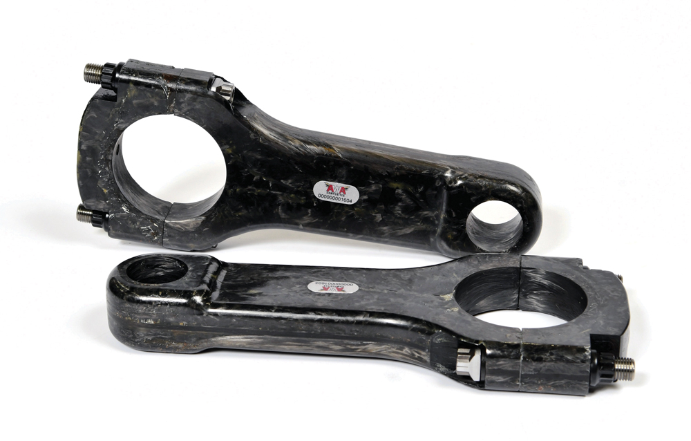
Introduced at the PRI Trade Show, AWA Composites’ composite connecting rod is half the weight of aluminum designs, and is projected to last an entire race season.
“I just shake my head sometimes when these guys come out with rules that they intend to save everybody money, when all it does is end up costing people more money,” said Tom Molnar of Molnar Technologies, Kentwood, Michigan.

Making this rule even more absurd is the realization that leading connecting-rod manufacturers are at the top of their game right now—and I-beam vs. H-beam is no longer a contentious and divisive feud between racers or manufacturers. There is a wide variety of models available to cover power levels for all racing venues. Behind significant computer and lab investments from their R&D efforts, companies have accurate data and simulation intelligence to supplement years of their own experience and customer feedback in building the proper connecting rod for specific racing applications—regardless of the preferred design. Balancing the priorities between strength, weight, and cost remains the critical challenge for the aftermarket.

“Engine builders are not looking for an anvil with two holes,” observed Gabriel Casella of Saenz Performance in Miami, Florida.

MARKET MOVERS
In addition to the current vitality among manufacturers, the connecting rod market may soon witness the working arrival of a disruptive technology that was first previewed at the PRI Trade Show two years ago. That’s when AWA Composites of Rolling Hills Estates, California, introduced its Sheet Matrix Composite, a fiber-woven composite with a proprietary weaving technique. Designed for Top Fuel engines, this connecting rod is half the weight of a conventional aluminum rod, yet is projected by company engineers to last an entire season instead of just 12 to 15 races. It has gone through a few changes since its debut.

“Now, by reason of our new design, we are in the final stages of getting some conclusive figures on those,” said Bryan Gill. “We have gone through alcohol testing. We have gone through Spintron testing. We have done forms of post-testing and material FEA. Now we are in engine testing.”

AWA is adapting this new composite to an OEM application as well as other race-engine components. The company expects to display pushrods, pistons, and wrist pins at this year’s PRI Show in December. But don’t hope for entry-level models or budget pricing.

“We wanted to show proof of concept of being able to master the tremendous cylinder pressures that are created by a nitromethane engine. Once we’re able to master that cylinder pressure requirement, everything else falls by the wayside to that,” Gill added. “We understand that composites are usually, in the grand scheme of things in the automotive industry, always on the premium end of anything. So, we are at the end of the ultra-premium market, and we do not really intend to offer what we call a budget composite rod.”

If AWA’s rod can last an entire season, then there will be an argument for saving money. “Cost versus benefit, I think that we are one of the better choices out there,” claimed Gill.

Auto Verdi in Soderbarke, Sweden, is another manufacturer that specializes in high-end connecting rods by focusing on NHRA Pro Stock, and officials don’t foresee expanding the line to other racing disciplines, unless a business case can be made.

“Everything is custom made. We work straight to the customer’s requirements,” explained Stefan Verdi, noting that most of the rods are an H-beam design. “We work with a couple of different materials. The up-level material is for Pro Stock. They’re looking for durability and rods that can withstand 80 to 100 runs.”

Auto Verdi does stock a small inventory for popular Saab and Audi applications, but other than Pro Stock the customer base is limited to a few diesel and land speed engines. Even though Auto Verdi has close ties with NASCAR and circle track engine builders via its oil-pump products, those markets are not candidates for connecting rods.

“That would entail a considerable machining investment,” said Verdi. “If we start producing and then they quit on us, we will have a problem.”

Most manufacturers offer a range of connecting rods to suit different applications and horsepower levels. But even some of those companies are rethinking their budget series.

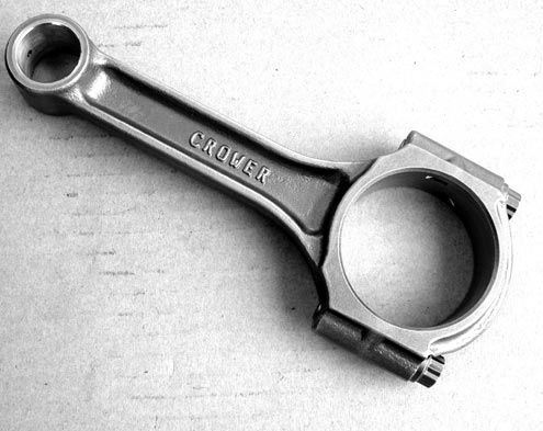
“We’re going to be discontinuing our Sportsman line,” said Shane Pulido of Crower Cams, San Diego, California. “Either today’s customer wants a really good rod, or they’ll go offshore—and we can’t compete with those in a budget line. Everything we offer is made in the US with US steel.”

3.%20Scat2.jpg

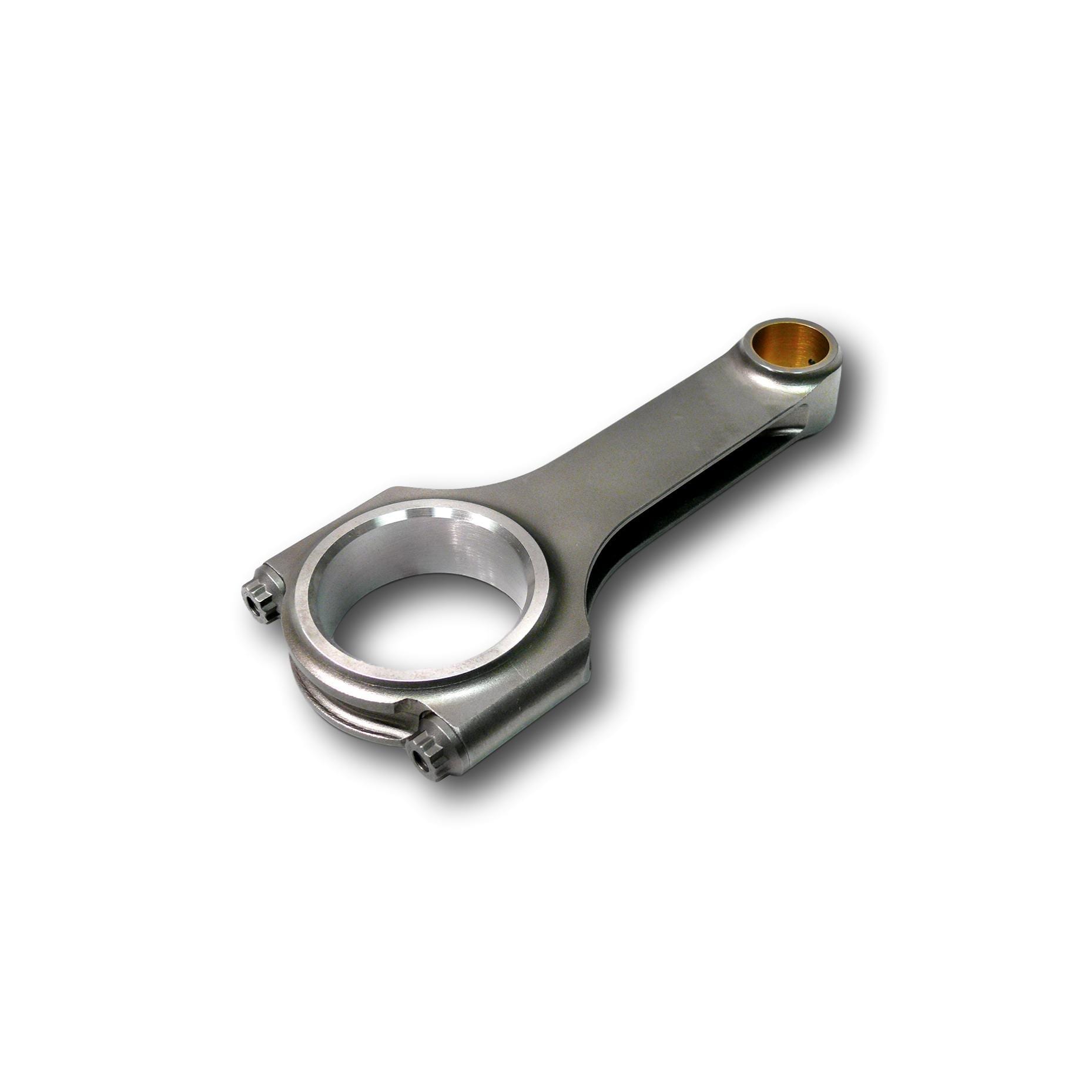
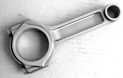
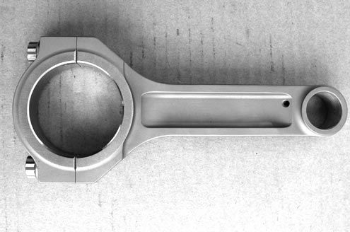
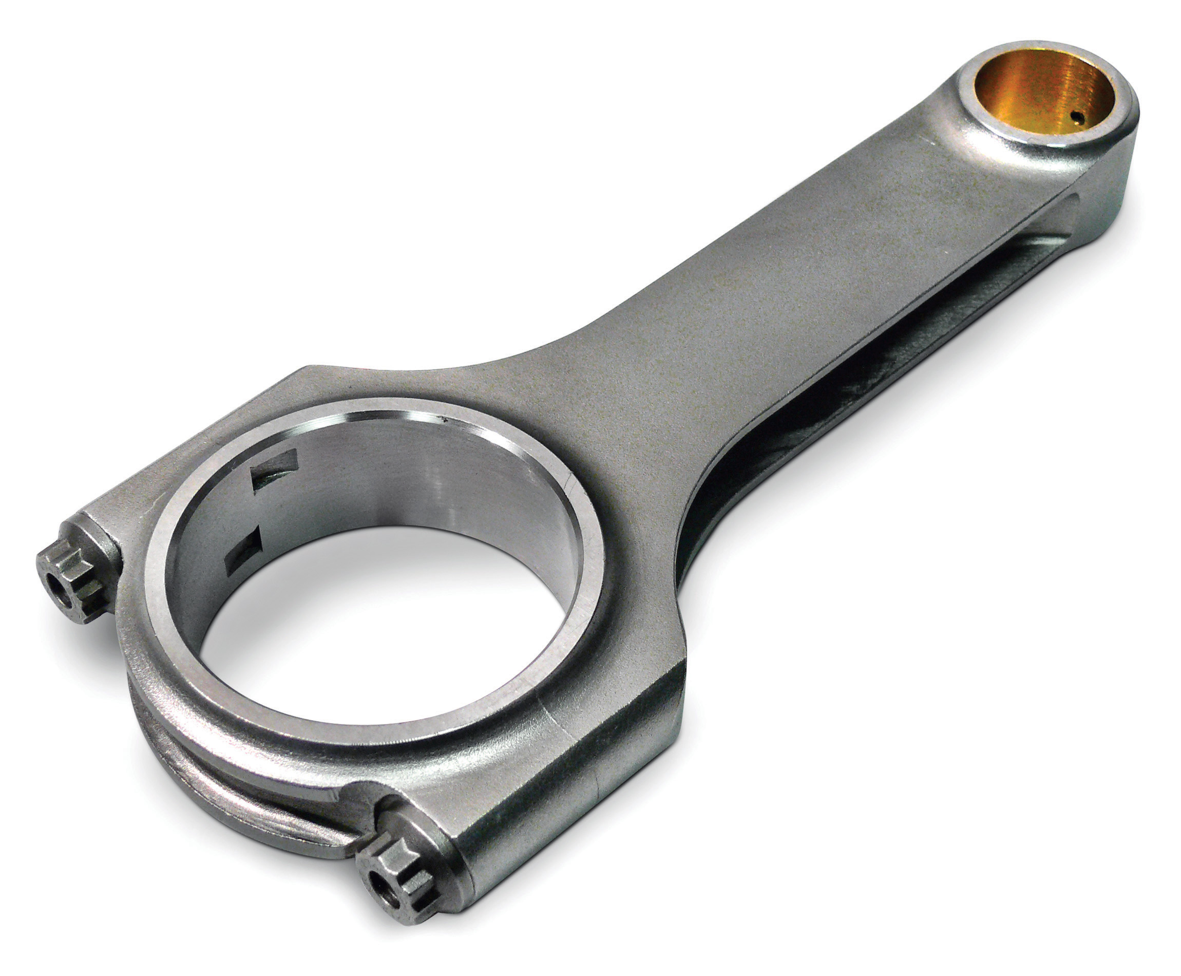
Providing a package deal motivates Scat Enterprises to offer a variety of connecting rod options, as the company often matches rods to the crankshaft, pistons, rings, and bearings for assembly. Pictured here is Scat’s Pro Sport H-beam model.
Crower has long focused on I-beam designs from billet steel, and one of its most popular lines is a tapered RBT (radial beam technology) Maxi-Light that removes excess material from non-critical stress areas. For popular applications, this rod is offered in a variety of weight and bolt configurations to suit the rpm, horsepower level, type of racing, and whether boost is involved. For example, in a small block Chevy the lightest Series 1 rod weighs 495 grams and comes with a 3/8 bolt for horsepower levels up to 550 on the drag strip. The Series 5 rod weighs 645 grams, comes with a 7/16-inch bolt, and is built for 1,000-plus engines at the strip.

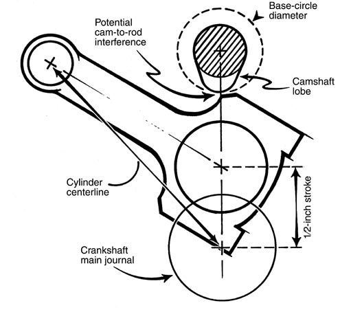
“For Series 6, we design those just for horsepower, rpm, and how much boost are running,” said Pulido, adding that the engineers evaluate the stroke, piston weight and piston speed at various crankshaft angles. “We can see the force at those points and rpm, and then we overbuild the rod by a long shot—because everybody wants to put it on the ragged edge and go for broke.”

Crower also has tips for inspecting rods between teardowns. “Looking at the bushing end to see if it’s squished out on the bottom from detonation. Also, your bearing’s going to tell everything, as far as how it’s wearing. If it’s wearing on the top end, then you have a detonation issue. If it’s wearing on the other end, you’re over-revving it,” said Pulido.

Catering directly to the customers’ specific needs is a common theme among manufacturers. K1 Technologies in Mentor, Ohio, focuses on H-beam designs. Instead of offering good-better-best choices, K1 tries to match the rod to the engine requirements.

“For certain applications, like small block Chevrolet, you have a lot of circle track people looking for a lightweight option,” explained Mike Skeen. “Whereas more of the drag race community is looking for a standard weight or a heavy-duty H-beam. The hardware stays consistently the same—it’s all ARP2000.”

Providing a package deal motivates Scat Enterprises in Redondo Beach, California, to offer a variety of connecting rod models. “The reason we have so many different rods is because we have the crankshafts to match them,” said Tom Lieb. “For instance, you’ve got a cast crank, and there’s no reason to buy an expensive H-beam rod. It’s just overkill on the pocketbook, but also the application.”

Scat’s strategy is to match up the crank, rods, pistons, rings, and bearings, then balance the unit so it’s ready for assembly. “We’ve gone step by step by step to match the application to the pocketbook. That’s about as simple as it gets,” added Lieb.

Again, Scat works with customers to determine the appropriate package. Street-rod and Super Stock dirt track engines might both dyno out at 500 peak horsepower, but the stress and durability requirements are quite different—and therefore the engine is set up differently.

4.%20DSC_4012.jpg

Weight restrictions sometimes limit engine builders, but lighter connecting rods are not always better. “It depends on the application. There are some lightweight rods that should not be in certain [segments],” one source told us.
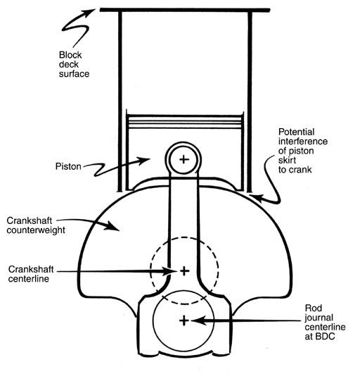
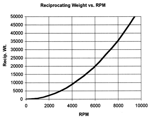
“You look at piston speed, which is based on the stroke,” said Lieb. “That will break a rod, and it has nothing to do with horsepower. Yes, we do have to do things with horsepower in mind, but it’s more piston speed, weight of the components, and the rpm you’re running.”

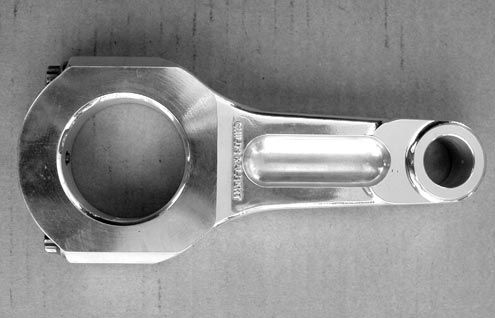
One of Scat’s premium rods is the Ultra HP Stroker, where the design game plan moved mass where it was needed to improve strength, then pockets were cut where strength wasn’t needed to lighten the overall weight.

“If you look at an I-beam, there’s no material there. But on an H-beam, because of the way we machine the rib, the cutter has a radius and leaves a triangular cavity in that section,” explained Lieb. “It has absolutely no effect on the rod’s strength.”

As racers educate themselves more in the deep technology of the sport, offering the customer a choice of steel materials provides another selling point. The most popular alloys are 4340, 4330 and 300M—although few companies will work with all three, and some partner with suppliers to develop a proprietary alloy.

“A lot depends on the application, and depending if it’s off the shelf,” said Julio Conception of Saenz Performance. “The 4340 tends to be a little bit heavier than 300M. Let’s say you want 1,200 horsepower—a 4340 rod would be a heavier rod than a 300M rod capable of holding 1,200 horsepower, but the 300M would be more expensive.”

Saenz offers both I- and H-beam, but focuses on I-beam in its Performance Series, while the budget-minded S-series is all H-beam. Most of the applications cover import engines, yet the company is expanding into the domestic market.

“Every customer is different, so we like to get in the conversation to know their application. Not only do we ask what you’re doing now, but how much horsepower are you looking to make in the future,” said Conception, who added that drag racers make up the better part of the company’s customer base, although midget racers using four-cylinder engines are a growing market. “Our first domestic rod is a 6.125-inch LS, and now we came out with the Ford 4.6-inch in the Performance series.”

Earning a strong reputation with dirt track engine builders has helped Dyer’s Top Rods in Forrest, Illinois, categorize its line of connecting rods to suit very specific engine-builder needs. “We also make rods for the off-road and LS markets,” said Roger Friedman. “And then we have Australian accounts for their sprint cars. We only make connecting rods.”

The product lineup is basically broken down by weight into different levels or series. For example, the H-series is the heaviest, while the XL-series is extra light—but there’s also ultra light and super light series. The rods are mostly standard H-beam or a tapered beam.

“After 20 years, we pretty much know what our customers are asking for. The range of lengths and weights is determined by the horsepower, rpm levels, and piston weight,” said Friedman.

Off-the-shelf rods are not fitted with hardware until all the customer requirements are noted. Then the big end can be finish-honed, as needed.

“We don’t have a lot of cookie-cutter stuff on the shelf,” added Friedman, noting that all Dyer’s rods are constructed from 300M steel. “It’s expensive material, but I believe it’s one of the strongest materials out there when the heat-treat is correct.”

Dyer’s originally machined its rods out of billet but finds the new forgings stronger. “A forging will give you grain structure around the big and little ends,” said Friedman.

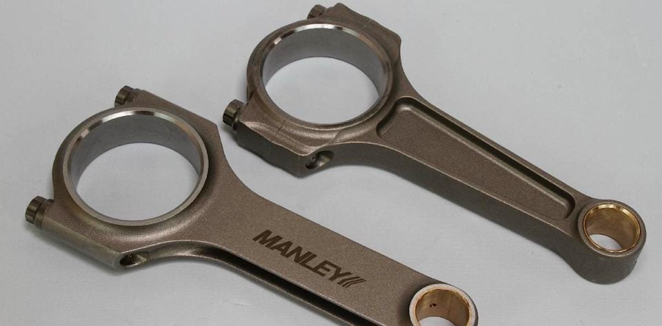
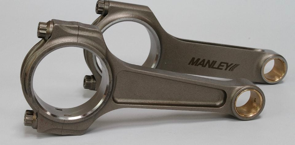
Molnar Technologies offers a variety of rod weights and lengths for popular applications, mostly in H-beam and constructed from 4340 steel alloy. For the small block Chevy, there’s a standard rod, mid-weight, and light-weight.

“Then we have our PWR ADR and PWR ADR Plus rods,” said Molnar. “The Plus rods are for the extreme guys—the spray and boosted engines when they start getting into the 35- and 40-pound boost ranges. We use proprietary ARP2000 bolts for everything.”

Molnar also manufactures a lightweight I-beam rod for circle track SBC engines and NHRA-approved Stock replacements.

“We take everything on an individual basis. We do not rate by horsepower because, quite honestly, nobody ever broke a connecting rod or a crankshaft due to horsepower,” said Molnar. “Horsepower does not break rods.”

Rod manufacturers are sometimes limited by rules—and not the farcical type that think a rod design is by nature a rev limiter. There are often weight restrictions, and certainly some organizations have outlawed exotic materials. The minimum weights required by some sanctioning bodies are intended to keep costs down. Still, lighter isn’t always better.

“It depends on the application. There are some lightweight rods that should not be in certain applications. Our lightweight late-model rods are made for a small four-barrel or a two-barrel application. You would not want to run that rod in a 410 sprint car. Everybody wants everything light, light, light, but there are limits,” said Molnar. “Five-hundred-gram rods are just not going to live in some of those applications, which is why we do not put horsepower ratings on them. We try and take each into each engine build on an individual basis, and try and help people get the right parts for their application.”

On the other side of the fence, Engine Pro in Wheat Ridge, Colorado, manufactures its line of rods from one-piece forgings that are initially produced offshore. “Then we finish machine them in Kansas City,” said Jesse Jones. “I like the idea of a single-piece forging, because it’s the same material, same circumstances for both pieces.”

All of the Engine Pro connecting rods are H-beam style forged from 4340 alloy. The customer has a choice between three ARP fasteners: 8740 chromoly, ARP 2000, or L19. Engine Pro suggests maximum horsepower levels based on the fastener selection, ranging from 700 up to 1,500 depending on the application.

Engine Pro also offers a lightened version of the H-beam for LS engines with ARP 2000 as standard bolts. Final weight comes in at 615 grams.

“Our goal was to make it the same weight as the OEM to replace the powdered metal rods,” added Jones. “Essentially, it’s the same construction as all the other H-beam rods, but thinned out in some areas where we can get away with it.”

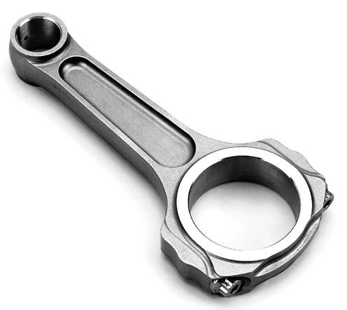
Eagle Specialty Products in Southaven, Mississippi, offers products for a wide variety of applications for a diverse range of end users.

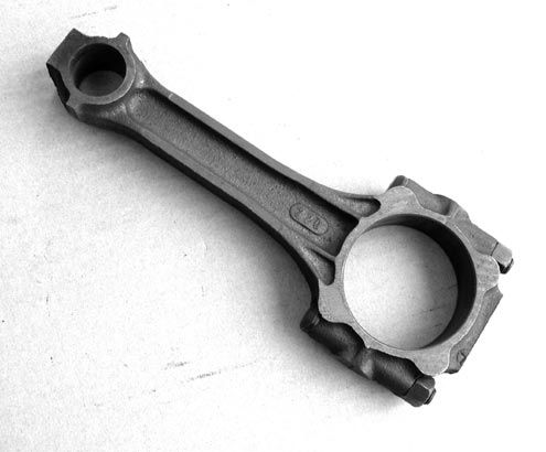
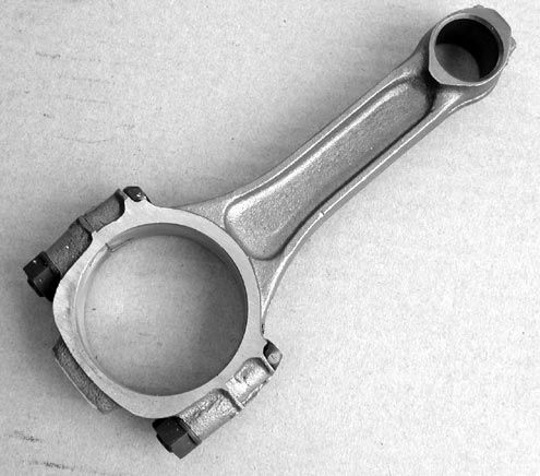
“Our rod lineup covers any form of grassroots and semi-professional racing,” said Alan Davis. “The only limitations would be custom or unique applications. Our strength is in our large-scale production. This drives the price down—not shortcuts in quality or material.

The entry-level SIR rod is forged from 5140 steel and designed for rebuilds, although some racers will use them in claimer applications. Next step up is the FSI I-beam made from 4340 steel followed by the top-of-the-line CRS 4340 H-beam rod. Both rods have bolt options.

“The H-beam rods are forged in two pieces,” noted Davis. “The cap is forged separately from the beam. This allows the grain flow of the rod cap to follow the stress lines. This feature would be impossible if the rods are forged as one piece and separated later.”

Eagle also offers an option called “Extreme Duty” in response to high-boost applications in the sport-compact market. “Most of these engines were making more than 260 horsepower per cylinder (1040 hp total). We start with the same H-beam rod and polish the entire rod to smooth out any microscopic pits or inclusions, which are starting points for fatigue failure,” explained Davis. “We then install the ARP Custom Age 625+ bolt, which have roughly a 27% higher tensile strength. The much higher clamping load helps keep the big end bore stable under extreme conditions, hence the name ‘Extreme Duty.’ We haven’t established a power rating on these yet.”

Eagle will introduce its fourth generation connecting rod in the near future. “I can’t tell you much more than that, but just like Eagle changed the performance landscape over two decades ago with our 3D rod, the 4D rod will do it again,” said Davis.

One of the companies touting I-beam construction is Callies, although it does offer limited applications in H-beam—starting with the value-added Compstar series. It’s forged and machined offshore, then sent to the US for finishing.

“We bring them here and do all the critical dimensions in our machines,” said Brook Piper of the Fostoria, Ohio-based company. “Then we go to our Ultra lineup, where we have an H-beam, but it’s for the high-volume applications only. The H-beam is a little easier to make than the I-beam. So, we can keep some costs out of it. So, the guy on the fence that really should use a better rod, then he could get into our H-beam instead of buying something from overseas.”

Callies uses 300M steel on all the Ultra rods. It also offers an Ultra XD that is designed for additional rod-to-cam clearance with stroker crankshafts. The company’s top-of-line offering is the Enforcer series.

“The Enforcer is for monster power-adder guys, whether it’s nitrous or boosted,” said Piper. “These are our I-beams on steroids—thickened up a little bit and heavy.”

5.%20Eagle1.jpg

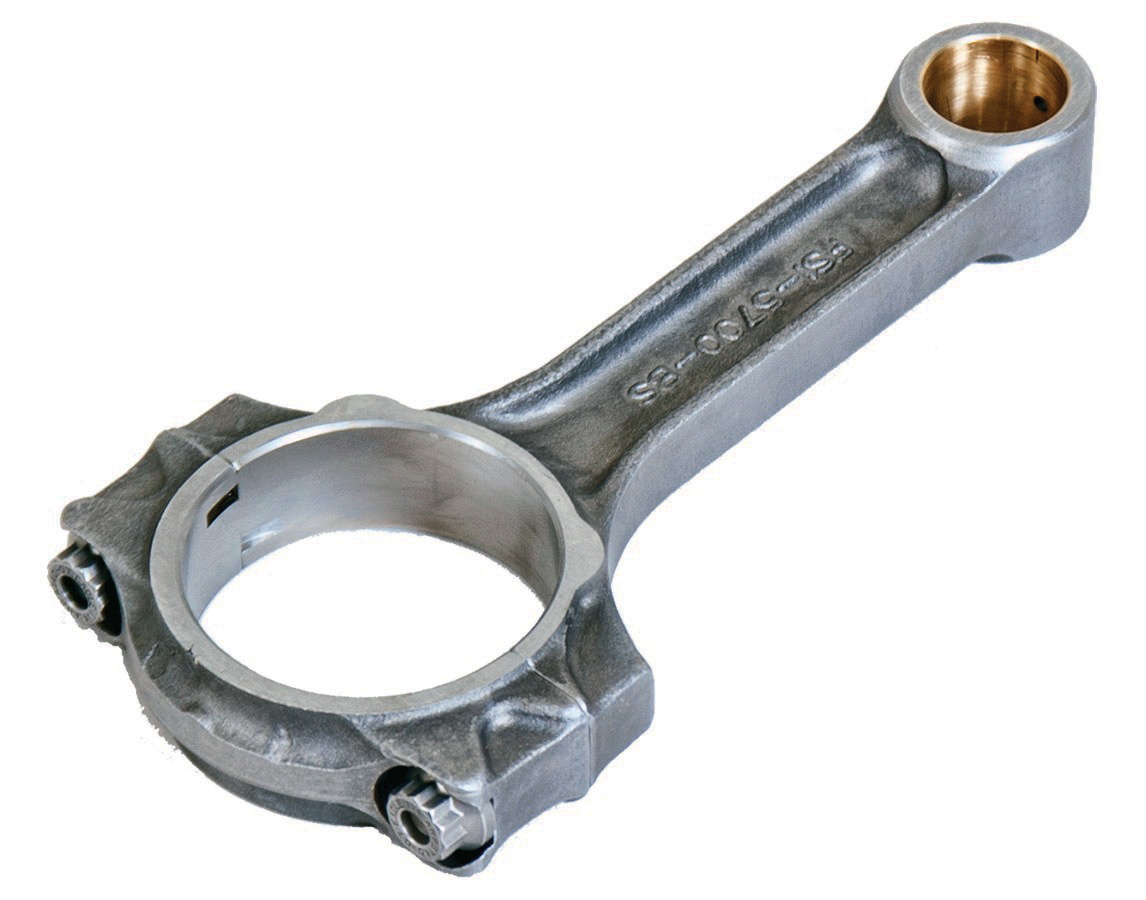
Eagle Specialty Products’ connecting rod lineup “covers any form of grassroots and semi-professional racing,” noted a company source. Pictured here is Eagle’s FSI I-beam rod forged from 4340 steel.
For circle track racers, Callies offers a lightweight version of the Ultra I-beam, but also caters to traditional H-beam racers. “We have been trying for years to educate them that the I-beam is stronger. But it is one of those handed-down things that they all believe in—H-beam is where you need to be in the circle track,” explained Piper. “So, we actually came up with the Ultra Dirt Series now.”

The Ultra Dirt is a lightweight H-beam design for small block Chevy that is available in three lengths with Honda-sized journals or the standard 2.000-inch journal.

BEYOND H-BEAM AND I-BEAM
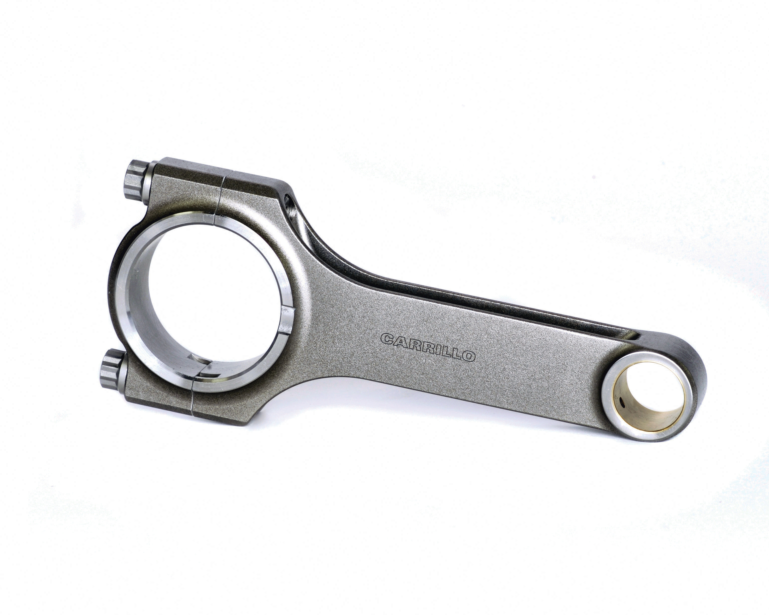
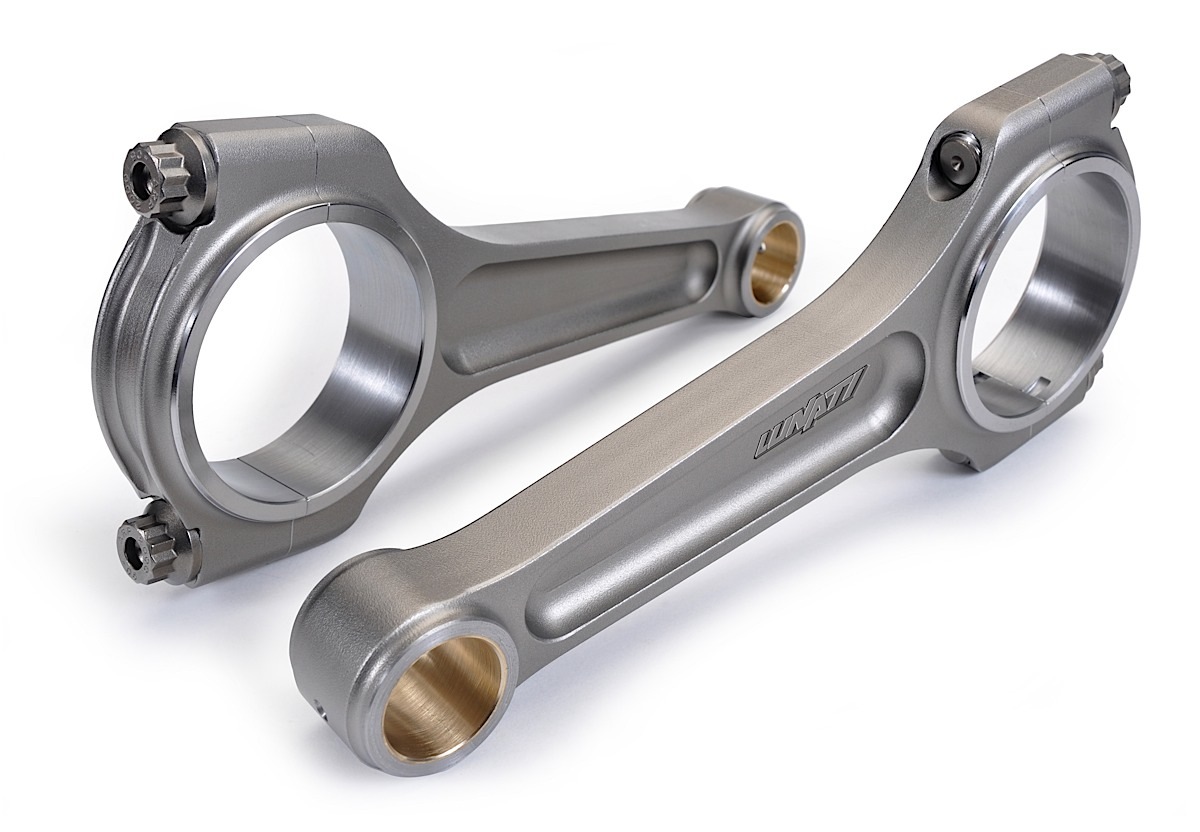
One way a manufacturer can help distinguish itself from the H-beam vs. I-beam debate is to come up with a new beam design. In addition to a traditional H-beam, CP-Carrillo of Irvine, California, offers an A-beam in its marketing plan. And Lunati has a new X-beam rod for the market.

“The A-beam is a lightweight I-beam style rod,” explained Richard Batchelor of CP-Carrillo. “It’s designed for lower horsepower, naturally aspirated engines. The Super A is a little beefier I-beam style designed for mild boost.”

6.%20CP2.jpg

Introduced into the motorsports world by Fred Carrillo, H-beam connecting rods are still considered CP-Carrillo’s “bread and butter,” according to a company contact, who added, “It’s what we’re known for and have done for decades.”
CP-Carrillo’s H-beam rods are constructed from a proprietary 4330 steel alloy, and may also be ordered in a tapered design. The company also offers a line of rods designed to meet NHRA requirements for Stock Eliminator replacement, and there’s an aluminum rod line for select applications, including drag racing.

Finally, CP-Carrillo makes a Bullet line of rods from 4330 near-net forgings to appeal to select budget markets. “It’s an I-beam style rod,” said Batchelor. “We made an investment in a few forgings for limited applications, and that is to keep the cost down. We buy the forgings in bulk, keep our costs down, and minimize machining operations where we can to make them more of a low-cost sportsman rod.”

The Bullet series should attract circle track engine builders and select sportsman drag racers, but the Pro H-beam is still CP-Carrillo’s signature offering.

“The H-beams are typically for bigger power, our bread-and-butter rod. It’s what we’re known for and have done for decades,” said Batchelor. “Fred Carrillo actually brought the H-beam into the motorsports world. The rod stayed pretty much the same structure for many decades. In the last 10 years we’ve made some changes, improving the designs through FEA and our own knowledge.”

Some 50 percent of the company’s business is with custom orders, and working closely with the engine builders is key to producing the correct product.

“What are your goals today and for the future?” asked Batchelor. “Sure, you want to make 600 horsepower now, but in two years are you going to be happy with that? Do you want to make a thousand horsepower? Design the rod for what you want to do with it, not just what you are doing with it.”

Over at Olive Branch, Mississippi-based Lunati, the company has introduced the new X-beam for LS and LT engine families. The design strategy is to combine the benefits of both I- and H-beam rods into a unique 4340 forging that is secured with ARP 2000 bolts. The company rates these 6.125-inch long rods up to 1,700 horsepower and 9,000 rpm. A lightweight version is also available with respective ratings of 850 horsepower and 9,000 rpm.

“Even though pricing on it is cheaper than our Signature series, it is the ultimate rod to have for any extreme horsepower application, whether that’s boosted or nitrous,” said Will Vance. “These rods were extensively tested in a dyno mule making closer to 1,800 horsepower and spun up to 9,000 rpm. When pulled down for inspection they looked new. We believe we have one of the baddest rods on the market with a price that any racer in this power range can afford.”

Lunati’s rod lineup starts with the Voodoo H-beam series that is rated up to 750 horsepower, followed by the Signature I-beam series with a rating of 1,200 horsepower.

“The Signature has been our premier rod for years and still extremely strong,” said Vance.

FINAL ANALYSIS
By all accounts, connecting-rod manufacturers show a willingness to work with individual teams to meet their specific needs, and have compiled proven track records to back up their designs. There are high-end racing classes that allow titanium, but all those rods are custom ordered and expensive. Other specialty classes like Top Fuel and some land speed engines are loyal to aluminum rods; however, if composites prove worthy of the hype, then that is a narrow segment that will be disrupted in the near future.

In a final analysis, however, current connecting rod strategies appear to be benefiting motorsports with few drawbacks. Computing power, testing, and mature wisdom combine to build a solid product that is versatile and cost effective. The future can only get better, if only because experience continues to enlighten the skeptics and teach the novices.

“I have seen people try things, had things not work out, then five years later you find people trying to do the same thing again,” explained Molnar. “It keeps going around and around. As new people come on board, they try all the things that they think are going to work…. Regardless of the brand, why don’t you call the manufacturer? Why go to someone that does not have any connection to what you are doing?”
 
Connecting Rod Tech: Forged And Billet Steel Rods


By DON CREASON FEBRUARY 14, 2013


Perhaps no part of an engine is hit with as much stress as the connecting rods. Designed to transfer linear motion and energy produced in the combustion chamber into a rotational motion at the crankshaft, connecting rods also serve as a key component in managing those same events and making a difference in an engine’s durability and life cycle.

“The rod package has to be custom tailored to the engine and the customer’s needs,” says Kerry Novak of Crower.

The rod package has to be custom tailored to the engine and the customer’s needs. -Kerry Novak, Crower


While different materials are used to construct connecting rods, this discussion will focus on steel — particularly billet and forged 4340 steel. For expert advice, we contacted some of the top figures in the rod industry, including Crower’s Novak, David Leach of Lunati, Alan Davis of Eagle Specialty Products and Manley’s Michael Tokarchik. We also reached out to Bryan Neelen at Late Model Engines for additional insight.

Understanding Rod Stresses

Connecting rods are subjected to both compressive and tensile forces during the 720 degrees of the four-stroke combustion cycle. On the compression stroke, pressures inside the cylinder increase, pushing back down against the rod. Depending on your engine’s compression ratio, power adders, etc, that pressure can rise quickly and steeply.

Compression ratio, boost pressure, ignition timing, camshaft overlap, horsepower, torque, engine speed and many other factors influence the stress on connecting rods.

On the combustion side, the rod must endure a sudden and violent direction change in addition to the pressure generated by the burning and expanding combustion gasses. That load on the rod can be calculated by multiplying the area of the bore (bore radius squared multiplied by pi) by the cylinder pressure. For example, a 4-inch bore would have a surface area of 12.566 inches. With a chamber pressure of 1,000 psi, the cumulative pressure on the rod at that point in the combustion would be 12,566 psi. And don’t forget the plug will fire just before the piston reaches top dead center, meaning the rod is still on it’s way up as the combustion mixture ignites, further increasing cylinder pressures that the rod must overcome.

This point in the combustion cycle also brings up the issue of pre-ignition, detonation and misfire. Knowing that the cylinder pressure increases once the air-fuel mixture is ignited, pre-ignition increases the load on the rod earlier, further straining it with compressive force. If the pre-ignition event is violent or frequent enough, the rod may be stressed beyond its limit.


I-beam vs H-beam


H-beam rods were born out of necessity during WWII when rod failures in fighter planes occurred as allied fighter pilots used nitrous oxide to boost break away speeds during dog fights.

There is constant debate about which is better, the I-beam or the H-beam rod. H-beam rods are usually more rigid and may better distribute the loads and compressive forces placed on them. They may be ideal for lower speed engines running power adders. There are trade offs for this improved strength. H-beam rods can be heavier, sometimes 100 grams more than comparable I-beam, and require greater clearance — something to consider with stroker cranks and large-bore cams. They also require more machining during the manufacturing process, adding to their expense.

I-beam rods can save weight and give additional clearance with only a small sacrifice in strength. This strength loss is minimal in high-end I-beam rods if the materials used are the same as a comparable H-beam. Additional material can be added to the design to further strengthen an I-beam but in some cases that may push overall weight closer to that of a comparable H-beam. I-beams are generally preferred for higher rpm applications.


Given the stress of these events, one might assume the exhaust stroke would be easiest on the connecting rod. The objective is simply moving the piston to push the spent gasses through an open exhaust valve. This, in fact, is the most dangerous time in the entire combustion process for a connecting rod. As Manley’s Michael Tokarchik explains, “The reason why is there’s no cylinder pressure buffering during that cycle.” With many camshafts having at least some type of intake and exhaust valve overlap, there is no cushioning pressure to slow the piston down.

As the crank makes the turn again over and past top dead center, inertial forces continuing driving the piston on it’s upward journey. This is the end of the exhaust stroke and beginning of the intake stroke. At this point, the rod is stressed in a tensile fashion. The big end must comply with the crank and begin the journey back in the opposite direction, while the small end wants to stay with the piston and continue upward. According to Tokarchik, this is actually where Manley sees the most failures occur in connecting rods.

During all of these directional changes, both ends of the rod are stressed, which can eventually lead to ovaling the bearing bores or complete failure.

The Manufacturing Process

There are two manufacturing processes used to make high performance connecting rods today: forging and billet. Both processes have unique pros and cons, and both produce a very strong finished product when quality manufacturing processes and materials are used.

Forging

Forging is a manufacturing process involving tooling dies, extreme heat and pressure. The die is essentially a negative of the rod, similar to a mold. A blank piece of metal is heated to a temperature where it is malleable and then forced into the die using high pressure, often referred to as hammering. The metal takes the shape in the form of a raw connecting rod, which then goes to final machining. This includes cutting and sizing the rod for the end cap, drilling holes for the rod bolts and pressing in bushings. Rods can also be stress-relieved, heat-treated and fine tuned to the proper weight.

Left: A raw forging from Eagle Specialty Products before final machining. Right: A finished, forged Eagle H-beam rod ready for shipping.

Grain alignment is a key factor in the strength of forged rods. “The hot forging process also compresses and correctly aligns the grain structure of the metal, for increased strength,” explains Lunati’s Leach.

“A forged part is pressed in such a manner that the grain of the metal is aligned to best withstand the loads they are put under,” echoes Davis from Eagle, adding that a flow or swirled appearance to the grain around the big end of the rod further increases its overall strength.


Perhaps the biggest disadvantage to forged rods is the initial production cost. The dies can cost tens of thousands of dollars to produce, with a specific die needed for each design. These dies eventually wear out and must be replaced. Changes to a design require either a new die, or altering the final machining process. While forging offers increased strength, it is also best suited for large volume manufacturing for a company to achieve a profitable return on investment.

Billet

Billet connecting rods are built from a single piece of flat forged steel. They are designed using a CAD-type computer program, then individually cut from a billet material using a water jet or other CNC-controlled machine.

“You can manufacture the connecting rod to the application, meaning the rods can be custom-tailored to each engine’s specific needs,” says Novak. Due to this flexibility, the sky is literally the limit in what can be designed and produced.


Left: A Crower Billet rod blank. Right: A finished Crower I-beam rod.

Since the billet-rod manufacturing process does not rely on retooling or new dies, designs can be easily changed to accommodate variations in strength requirements, weight, rod length, crank- and wrist-pin diameter, oiling and more.

“We can take a rod from our Maxi-Light design that can handle 450 horsepower, and using that basic rod as a blueprint, design one that may have the same dimensions custom tailored for applications that make over 2,000 horsepower,” says Novak.


The flexibility of billet rod manufacturing allows for the manufacturing of everything from a motorcycle rod to high performance V8’s and even high performance big rig diesels.

That rapid manufacturing capability allows billet rod manufacturers to manufacture rods for a snowmobile or motorcycle up to a big-rig diesel engine on the same equipment.

The downside to billet when compared to forging is the grain structure in the rod. Since a billet rod is cut from flat steel, the grain doesn’t swirl and flow around the big end of the rod, as in a forged application. With a billet rod, the grain remains straight or vertical throughout the rod.

Since billet rods are often produced in smaller batches or in custom configurations, more time may be needed in creating the design, machine setup and final finishing. Because of the additional labor involved and smaller production runs, billet rods can be more expensive than a forged rod of the same material.

Materials

Whether forged or billet, rod strength is dictated in large part by the materials used. When it comes to drag racing and street performance, engine builders have made steel the material of choice in most applications.


Why Steel

Not all 4340 alloy steel is the same. That makes it critical to know the steel mill, exact alloy of the material, and to deal only with the most reputable metal suppliers. -David Leach, Lunati


It used to be that high-rpm engines used aluminum or other exotic materials to give rods high strength and light weight. As costs have risen and engine designs evolved, however, builders moved back to steel.

Bryan Neelen of Late Model Engines (LME) explains: “The weight below the wrist pin is not as big of a concern as the weight above it.” This is just one of the reasons for the move by many racers and engine builders back to steel. Cost, durability, and longevity are some of the others.

Another big factor is clearance. In high-rpm racing engines such as Pro Stock, valvetrain stability becomes increasingly important. Pro Stock rules allow for a larger camshaft bore, and big-bore cams provide higher valve lift in addition to improving rigidity and valvetrain stability. The additional material necessary for aluminum rods will often interfere with the rod-to-camshaft clearances. By using a high-strength steel rod, larger cam bores can be utilized without interference.


The use of high quality 4340 steel is imperative to ensuring the strongest possible connecting rod.

The most common type of steel used for high-performance connecting rods is 4340 chromoly steel. 4340 has a tensile strength of 145,000 psi. Its hardness, ductility and other properties will vary based on the heat treatment applied to it. 4340 may also be referred to as aircraft grade or aircraft quality steel.

The entire steel manufacturing process determines the strength of these materials, as well. A simple designation of 4340 steel does not necessarily mean that two steel suppliers construct the final product to the same standards or with the same processes.

“Not all 4340 alloy steel is the same,” says Leach. “That makes it critical to know the steel mill, exact alloy of the material, and to deal only with the most reputable metal suppliers.”


Quality rod bolts are also critical to the strength of a connecting rod.

Heat treat, drawing, hardness, ductility, and grain structure all play a vital role in the quality of the steel, thus affecting the final characteristics of a connecting rod.

Rod Bolts

All rod manufacturers emphasize the importance of rod bolts. No other fastener in a car is under as much stress as the rod bolt.

“The purpose of the rod bolt is to keep the bore round, and keep a proper amount of pre-load at the body-cap interface — at top dead center during the exhaust stroke,” says Manley’s Tokarchik.

This is the moment where the rod bolt is most stressed and where rod-bolt failures often occur. As explained earlier, the combustion stroke puts stress on the rod bolts, but the inertial events occurring at top dead center during the exhaust stroke can take a greater toll.


Builders should follow the rod-bolt manufacturer’s instructions for installation.

“There are a lot of concoctions out there for rod bolts, and some engine builders have even developed their own. The fact is that you should stick with what the rod bolt manufacturer recommends for lubricant and tightening procedure and not deviate from that,” says Davis.

Rod Selection

Choosing the proper connecting rod for your application is as vital as selecting the correct camshaft. It’s also just as involved of a process, one in which you should know several things about your combination prior to making a decision. Checking with the engine builder and manufacturer is also a good idea.

“When we design a forged part, we want to make it strong enough to handle what we expect our customers to be using. It also has to be light enough to perform in the proper rev range,” says Davis.

There are several factors that those consulted agree should be considered when selecting rods. Aside from the engine’s basics, such as the stroke and displacement, you also need to know the following:

At the end of the day if your components are not up to the power levels that they will see, it doesn’t matter who your engine builder is. -Bryan Neelen, LME


  • Piston package weight (piston plus rings)
  • Operating rpm
  • Horsepower
  • Torque
  • Block type
  • Crank material
  • Compression ratio
  • Heads
  • Cam specs
  • Weight of vehicle
  • Gear ratio


Rod selection eventually all comes down to relying on the manufacturer and engine builder to deliver the proper package for a particular engine application. Neelen tells us, “At the end of the day, if your components are not up to the power levels that they will see, it doesn’t matter who your engine builder is.” Choosing the proper connecting rod for an engine will help to ensure the best outcomes possible on race day, and should also increase the useful life of that engine.
 
https://www.onallcylinders.com/2015/09/11/rod-school-how-to-choose-the-right-connecting-rods/

Rod School: How to Choose the Right Connecting Rods
Posted by David Fuller on September 11, 2015 at 4:50 pm
wiseco_boostline_rod_pri_show.jpg

(Image/Wiseco)
Steel or aluminum? H-beam or I-beam? And don’t even get us started on rod length and rod ratios!

Yes, there are a lot of factors that go into choosing the right connecting rods for your engine. Proper rod selection is undoubtedly one of the most important decisions you can make when building an engine. Connecting rods not only affect how your engine fits (or doesn’t fit) together, they also play a role in engine performance and longevity.

That’s why we turned to the experts at Eagle Specialties, Lunati, and Callies Performance for tips on how to choose the right connecting rods for your engine and application. Not surprisingly, horsepower and torque are major factors in the equation. According to Alan Davis of Eagle Specialties, it’s not just about overall power and torque levels, but also the way power is made.

“Horsepower, torque, and rpm are all things to consider,” Davis said. “But you must also consider the application and the environment the engine will be used in and how the power is made. For instance, a 600-horsepower, naturally aspirated engine that turns 10,000 rpm will have far different stresses than a 600-horsepower, supercharged engine or a 400-horsepower engine with a 200 shot of nitrous.”


Depending on the application, different types of stresses are applied to the connecting rods. For example, large amounts of torque will yield heavy compression and bending loads on the rods. High rpms, on the other hand, cause mostly tensile-loading or stretching forces. In most cases, connecting rods don’t fail on the compression stroke; rather, they break apart on the exhaust stroke at high-rpm operation due to tensile loading.

“This (tensile loading) is also much harder on rod bolts than horsepower and torque,” Davis said. “Other factors to consider are piston weight and the stroke of the crankshaft. Also, different fuel and nitrous use will have a different effect on combustion and how the load is delivered to the rods.”

In addition to engine power and rpm levels, other factors important to connecting rod selection are:

  • Application: street, drag race, endurance racing, etc.
  • Engine dimensions: stroke, rod ratio, piston height, etc.
  • Rod weight vs. reliability
  • Budget (for most of us, it plays a role)
All of these things will help determine the rod length, material, and configuration that’s best for your application.

I-Beam vs. H-Beam

I-beam connecting rod
There are two basic styles of connecting rods: I-beam and H-beam.

Most stock connecting rods are I-beam. Stock V8 connecting rods can handle upward of 400 horsepower and 6,500 rpm. Once you exceed those performance levels, you’ll need to consider aftermarket connecting rods. Depending on the type of steel used (we’ll get more into that below), aftermarket I-beams can handle hefty compressive loads, offer good tensile strength, and are often more lightweight than H-beams.

The connecting rod’s ability to handle compression loads and tensile loading is dependent on the cross-sectional area of the beam. Therefore, aftermarket I-beam rods typically have a thicker cross-section in critical areas to increase strength. H-beam connecting rods, however, use a completely different design to increase stiffness and strength.


H-beam connecting rod
H-beam connecting rods incorporate two large, flat sides with a thin section in the middle. This design makes these rods more rigid and able to handle compression forces.

“H-beam is a stronger design when bending stress is considered,” Davis said. “H-beam rods are more difficult to machine, so they are often more expensive. I-beam rods are easier to produce and can sometimes be lighter than H-beams. All other variables being equal, H-beam rods are the strongest design.”

Whether you choose H-beam or I-beam, overall strength and reliability is dependent upon the material, weight, and cross-section of the rods, said Nick Norris of Callies Performance Products.

“All of our I-beam, and some of our H-beam rods have a tapered beam design,” he said. “Our H-beam design is a very good part that is typically 20 grams lighter than our I-beam in the standard configuration. We consider our I-beam to be the heavy duty rod due to larger material cross sections and pin support structure.”

So what about materials?

Steel vs. Aluminum vs. Titanium
When it comes to connecting rods, the main material options are steel, aluminum, and titanium. Again, the right choice for you will depend on the variables (power, rpm, application, etc.) above.

Steel connecting rods are made with various types of materials and manufacturing processes. For example, cast steel connecting rods were used in many 1960s and 70s vehicles, but they are not great for any type of performance applications. Most aftermarket steel connecting rods are made from forged steel.

There are different types of forged steel based on the grade of material. Eagle Specialties, for example, uses a 5140 steel for its entry-level rods. For more highly modified competition applications, most manufacturers, including Eagle Specialties, utilize high-carbon 4340 or 4330 steel.

“For high-end competition, our rods are forged and heat-treated to SAE/ASTM specification 4340 steel,” Davis said. “This specification allows for some variation in alloying elements. Eagle has held our steel to a tighter tolerance and have achieved a slightly higher yield strength than ‘typical’ 4340 steel.”

Depending on the specific material, steel connecting rods are suitable for most applications.

Aluminum rods can be as much as 25-percent lighter than steel rods, making them a popular choice with racers. The lighter weight reduces the overall mass of the reciprocating assembly, allowing the engine to rev faster and higher. According to Davis, aluminum is also a great choice for supercharged applications.

“Aluminum, while not as strong as steel, is often used in very high power blower engines,” he said. “This is due to the fact that aluminum ‘gives’ slightly under violent combustion and acts like a ‘shock absorber’ so that the harmful shock of combustion does not propagate to the rod bearing and cause a bearing failure.”

The downside to aluminum rods is their fatigue life. Aluminum connecting rods have a more limited service life than steel and can begin to stretch, especially when they’ve made many passes down the dragstrip. However, many aluminum connecting rod manufacturers argue that a good set of aluminum rods can last up to 100,000 miles in street applications. So it really comes down to your application and budget. If you’re a racer and can afford to change out rods more frequently, aluminum is a good choice. If you’re on a budget or if your engine is a high-torque, low-rpm mill, steel may be a more cost-effective option in the long run.

Titanium is a third option.

Titanium connecting rods combine the lighter weight of aluminum with strength that’s more comparable to steel. That makes them a viable option for drag cars or sprint cars that require quick throttle response. However, they are very expensive.

“Titanium is slightly weaker than steel, but due to the extremely light weight, far less stress is realized,” Davis said. “So effectively, titanium can be considered stronger as far as the entire system is considered. It is a tricky material, though; and it doesn’t come without a price. And I’m not just talking about dollars.”

Special Treatments
Connecting rod material is the only thing that determines strength.

“These are important factors, but don’t even come close to telling the story,” Davis said.

You’ll also want to make sure the rods have been heat-treated, which is required for a material to meet most SAE/ASTM specifications. Shot peening is common and an absolute must for machined or forged parts, according to Davis. Polishing helps reduce microscopic pits, inclusions, and lead to extended fatigue life; however, it must be done properly. Aggressive grinding or polishing can actually do more harm than good.

Cryo-treatment is another finishing process. This can be thought of as an extension of the heat-treatment process. Cryo-treatment essentially cools the material to a much lower temperature than room temperature right after the heat treatment ends. According to Davis, the benefits of this process is a marginal strength increase by about 2-3 percent and increased wear resistance.

Rod Length and Rod Ratio
Rod ratio is the length of a connecting rod (center to center) divided by the stroke of the crankshaft. This number can have a direct effect on power, torque, engine efficiency, and piston wear.

Here are some common stock connecting rod lengths:

CHEVY

FORD

As a general rule of thumb, lower rod ratios are associated with lower-rpm engines. Higher rod ratios typically work with high-revving, high-rpm engines. Generally speaking, the rod ratio for gasoline-based, automotive engines operating in typical rpm ranges will be about 1.45:1 –1.7:1, with some race engines up to a 2.1:1 rod ratio.

There are a couple schools of thought with rod ratio.


Rod ratio, in this image, is B divided A. (Image courtesy of MustangsandFords.com)
“The higher the maximum rod angle (and lower the rod ratio), the more piston side-loading you will have,” Davis said. “This results in higher friction, and accelerated piston skirt wear. However, before you throw the longest rod in everything you build, understand that lower rod ratios tend to “mix” the air/fuel better in the cylinder due to more aggressive piston acceleration. This can result in higher efficiency, torque, and power can be the result.”

According to Norris: “It’s still more typical to use the longest rod available to work within the stroke, the deck height, and available piston-compression heights. This helps keep the piston weight down, and in turn, the stresses on the connecting rod. An instance where that may not hold true would be a boosted or heavy nitrous application where the piston would need more compression height to allow the ring pack to be moved down.”

Most agree that rod length/rod ratio selection should be part of a larger equation.

“The length of the rod has an effect on the dwell time of the piston at TDC,” Norris said. “In cases where the stroke is short enough to allow some flexibility in rod selection, it can be factored in with port flow, valve timing, and rpm range to optimize the engine for a specific application.”

A Quick Word on Rod Bolts
It is imperative that you pay attention to the connecting rod bolts when you purchase and install your new connecting rods. These bolts are the single highest-stressed fastener in your engine, according to Davis.

“We use ARP 8740, 2000, L19, and Custom Age 625+ materials,” he said. “Just like choosing the correct bolts is important, following manufacturers’ instruction for tightening, lubrication, and care is also vital to the bolt (and your engine’s) life.”

Avoid over-stretching the rod bolts during engine assembly. When new rod bolts are installed and tightened down to fit bearings, make sure to use the right lubricant on the threads.

By choosing the right connecting rod material, size, and style (and don’t forget the right bolts, too), you’ll ensure maximum performance and reliability from your engine.

What more could you ask for?


Tags: connecting rods


Author: David Fuller
 
https://rehermorrison.com/tech-talk-93-all-about-connecting-rods/
dialcalps.jpg

tech talk #93 – All About Connecting Rods


By David Reher, Reher-Morrison Racing Engines

“I can’t say categorically whether steel or aluminum connecting rods will make an engine perform better.”


Back in the early ’70s, when Buddy Morrison and I were building engines in the back room of Mansfield Auto Supply, choosing connecting rods was simple.


We used stock Chevy small-block rods, replaced the tiny 11/32-inch bolts, and hoped for the best. Later on, when we were building small-block Modified and Comp motors by the dozen, we graduated to aluminum rods. We figured these were real racing engines, and that’s what the fast guys used. Steel rods in racing engines? We thought those were just for roundy-round racers.

Of course, we also had a rotary telephone, a television with vacuum tubes, and we shipped parts by Greyhound bus because FedEx didn’t exist. Fast forward to 2015, and everything has changed – especially connecting rod technology.

Today the choices are nearly unlimited – and at times bewildering for racers. Materials include a variety of advanced steel, aluminum, and titanium alloys, and an alphabet soup of styles – A-beam, H-beam, I-beam, etc. Even production connecting rods have changed dramatically. Today many engines are assembled with powdered metal rods with fractured caps – the caps are literally broken off to create a textured mating surface. I’m thankful that Buddy and I didn’t have to rebuild those at Mansfield Auto Supply!

So what’s the right connecting rod for your racing engine? As always, it depends on the purpose, the power level, and the budget.

For the sake of simplicity, I’ll focus on steel and aluminum rods. We experimented with titanium connecting rods in our Pro Stock engines for a while, but the cost and complexity of titanium were drawbacks. Now Chevy LS1 engines are assembled with titanium rods at the factory, which shows just how radically technology has changed.

Aluminum rods have been the first choice in unrestricted classes for decades, from Top Fuel to the fast sportsman eliminators. Aluminum is lightweight, easily machined, and serves as a shock absorber to cushion loads on the crankshaft. Its downsides are also well documented – aluminum has a shorter fatigue life than steel and requires larger cross-sections to achieve comparable strength. If a customer wants to make 400 runs between engine rebuilds, I’ll steer him away from aluminum rods.

There was a time when I would have laughed at the notion of steel connecting rods in a Pro Stock engine, but the reality is that most Pro motors are now equipped with steel rods. These aren’t your father’s rods – they’re technically sophisticated, artfully machined, and command a premium price.

One of the advantages of steel rods is that the piston-to-head clearance can be minimized, which in turn raises the dynamic compression ratio. The engine builder’s goal is to maximize compression by using the smallest piston-to-head clearance that prevents hard contact between the components. The pistons are most likely to kiss the cylinder heads on the overlap stroke when the intake and exhaust valves are open and cylinder pressure is low. The unloaded rod is stretched to its maximum when the piston reverses direction at Top Dead Center. On the compression stroke, both valves are closed and cylinder pressure pushing against the piston compresses the assembly and inhibits rod stretch.

Aluminum rods typically require .010-inch more clearance than steel rods to accommodate their greater stretch under load and higher expansion rate when heated. This translates to an increase of about 1.5 cc in combustion volume at TDC (depending on cylinder diameter) on the compression stroke, with a corresponding reduction in dynamic compression ratio

Does this make a difference? It’s difficult to compare rods directly, but we did test steel vs. aluminum rods using two high-end, high-rpm engines. In both instances, we didn’t see a significant performance difference on the dyno or on the track. So I can’t say categorically that one or the other will make an engine perform better.

There are some practical considerations when choosing a connecting rod. Steel rods can become prohibitively heavy in large displacement, long-stroke engines. In a big-inch engine, steel rods can weigh more 900 grams, while comparable aluminum rods would be around 600 grams. That’s a significant difference in bobweight. The reality is that an engine with less rotating mass will accelerate faster, which tips the scale in favor of aluminum rods in these applications.

I’ve learned to appreciate the cushioning effects of aluminum rods. Pro Mod engines with nitrous oxide injection experience brutal spikes in cylinder pressure and are prone to detonation. This extreme cylinder pressure hammers the crankshaft and wrist pins unmercifully. Aluminum rods definitely extend crankshaft life and reduce distortion of the wrist pin bores in nitrous-injected engines.

I’ve also learned that wrist pins are not the place to save weight. Back in the Modified days, we thought that lightweight, thin-wall wrist pins were really neat. If they didn’t break, we kept making them thinner and lighter. Now I know that the wrist pins must be rigid to prevent damage to the connecting rod and piston. The wear and fretting in the pin bores that I once thought were caused by inadequate clearance and lubrication are actually due to distortion of the wrist pins. It takes horsepower to mess up rod bushings and pin bores, and that’s wasted power.

The benefits of rigid wrist pins are readily apparent in nitrous-injected Pro Mod motors. We’re now installing massive tool steel wrist pins that don’t distort under high loads, and consequently the rods’ little ends look terrific.

Some racers pine for the good old days. If that means going back to the stock connecting rods we used in the ’70s, count me out.

Share this:
 
https://rehermorrison.com/tech-talk-93-all-about-connecting-rods/

tech talk #93 – All About Connecting Rods


By David Reher, Reher-Morrison Racing Engines

“I can’t say categorically whether steel or aluminum connecting rods will make an engine perform better.”


Back in the early ’70s, when Buddy Morrison and I were building engines in the back room of Mansfield Auto Supply, choosing connecting rods was simple.


We used stock Chevy small-block rods, replaced the tiny 11/32-inch bolts, and hoped for the best. Later on, when we were building small-block Modified and Comp motors by the dozen, we graduated to aluminum rods. We figured these were real racing engines, and that’s what the fast guys used. Steel rods in racing engines? We thought those were just for roundy-round racers.

Of course, we also had a rotary telephone, a television with vacuum tubes, and we shipped parts by Greyhound bus because FedEx didn’t exist. Fast forward to 2015, and everything has changed – especially connecting rod technology.

Today the choices are nearly unlimited – and at times bewildering for racers. Materials include a variety of advanced steel, aluminum, and titanium alloys, and an alphabet soup of styles – A-beam, H-beam, I-beam, etc. Even production connecting rods have changed dramatically. Today many engines are assembled with powdered metal rods with fractured caps – the caps are literally broken off to create a textured mating surface. I’m thankful that Buddy and I didn’t have to rebuild those at Mansfield Auto Supply!

So what’s the right connecting rod for your racing engine? As always, it depends on the purpose, the power level, and the budget.

For the sake of simplicity, I’ll focus on steel and aluminum rods. We experimented with titanium connecting rods in our Pro Stock engines for a while, but the cost and complexity of titanium were drawbacks. Now Chevy LS1 engines are assembled with titanium rods at the factory, which shows just how radically technology has changed.

Aluminum rods have been the first choice in unrestricted classes for decades, from Top Fuel to the fast sportsman eliminators. Aluminum is lightweight, easily machined, and serves as a shock absorber to cushion loads on the crankshaft. Its downsides are also well documented – aluminum has a shorter fatigue life than steel and requires larger cross-sections to achieve comparable strength. If a customer wants to make 400 runs between engine rebuilds, I’ll steer him away from aluminum rods.

There was a time when I would have laughed at the notion of steel connecting rods in a Pro Stock engine, but the reality is that most Pro motors are now equipped with steel rods. These aren’t your father’s rods – they’re technically sophisticated, artfully machined, and command a premium price.

One of the advantages of steel rods is that the piston-to-head clearance can be minimized, which in turn raises the dynamic compression ratio. The engine builder’s goal is to maximize compression by using the smallest piston-to-head clearance that prevents hard contact between the components. The pistons are most likely to kiss the cylinder heads on the overlap stroke when the intake and exhaust valves are open and cylinder pressure is low. The unloaded rod is stretched to its maximum when the piston reverses direction at Top Dead Center. On the compression stroke, both valves are closed and cylinder pressure pushing against the piston compresses the assembly and inhibits rod stretch.

Aluminum rods typically require .010-inch more clearance than steel rods to accommodate their greater stretch under load and higher expansion rate when heated. This translates to an increase of about 1.5 cc in combustion volume at TDC (depending on cylinder diameter) on the compression stroke, with a corresponding reduction in dynamic compression ratio

Does this make a difference? It’s difficult to compare rods directly, but we did test steel vs. aluminum rods using two high-end, high-rpm engines. In both instances, we didn’t see a significant performance difference on the dyno or on the track. So I can’t say categorically that one or the other will make an engine perform better.

There are some practical considerations when choosing a connecting rod. Steel rods can become prohibitively heavy in large displacement, long-stroke engines. In a big-inch engine, steel rods can weigh more 900 grams, while comparable aluminum rods would be around 600 grams. That’s a significant difference in bobweight. The reality is that an engine with less rotating mass will accelerate faster, which tips the scale in favor of aluminum rods in these applications.

I’ve learned to appreciate the cushioning effects of aluminum rods. Pro Mod engines with nitrous oxide injection experience brutal spikes in cylinder pressure and are prone to detonation. This extreme cylinder pressure hammers the crankshaft and wrist pins unmercifully. Aluminum rods definitely extend crankshaft life and reduce distortion of the wrist pin bores in nitrous-injected engines.

I’ve also learned that wrist pins are not the place to save weight. Back in the Modified days, we thought that lightweight, thin-wall wrist pins were really neat. If they didn’t break, we kept making them thinner and lighter. Now I know that the wrist pins must be rigid to prevent damage to the connecting rod and piston. The wear and fretting in the pin bores that I once thought were caused by inadequate clearance and lubrication are actually due to distortion of the wrist pins. It takes horsepower to mess up rod bushings and pin bores, and that’s wasted power.

The benefits of rigid wrist pins are readily apparent in nitrous-injected Pro Mod motors. We’re now installing massive tool steel wrist pins that don’t distort under high loads, and consequently the rods’ little ends look terrific.

Some racers pine for the good old days. If that means going back to the stock connecting rods we used in the ’70s, count me out.

Share this:
related threads
http://garage.grumpysperformance.co...ng-rod-bolt-stretch-preload.11050/#post-99097

http://garage.grumpysperformance.com/index.php?threads/bearing-clearances.2726/page-2#post-81749

http://garage.grumpysperformance.com/index.php?threads/rod-bolts-rpm-vs-stress.341/#post-30778

http://garage.grumpysperformance.co...tion-of-crank-durring-short-blk-assembly.852/

http://garage.grumpysperformance.com/index.php?threads/precision-measuring-tools.1390/

http://garage.grumpysperformance.com/index.php?threads/which-torque-wrench.342/#post-59396

http://garage.grumpysperformance.com/index.php?threads/connecting-rod-strength-h-vs-i-beam.1168/

http://garage.grumpysperformance.co...ng-and-basic-piston-ring-info-youll-need.509/

http://garage.grumpysperformance.com/index.php?threads/rod-bolts-rpm-vs-stress.341/#post-30778
 
Last edited:
connecting rods and the rod bolts that hold them together are some of the higher stressed components in any performance engine, and knowing that it really tends to require the engine builder to look into his options, and do the required research.
I generally look at SBC connecting rods a bit like fan belts and clutch discs , they are simply a component that's reasonably inexpensive in most cases and since they take a great deal of excessive stress they are best replaced when any engine is rebuilt, especially considering the fact that the cost incurred for a skilled machine shop to resize, mag check the rods for stress cracks, and replace the rod bolts easily exceeds the cost of the better aftermarket connecting rods with in most cases much stronger rod bolts and a easily demonstrable, increase of at least 50% or up to 200% in strength, in the better designed name brand rods.
there are a few OEM BIG BLOCK CONNECTING RODS that are worth rebuilding, but even there, the better aftermarket rods hold some significant advantages in strength, and clearance.
considering the extensive damage that can and usually does result if a rod bends or a rod bolt fails, its well worth the builders time and the required effort to buy, inspect and install stronger connecting rods, rather than just reinstall OEM rods with millions of compression & stretch stress cycles already endured.


http://www.callies.com/connecting-rods/

https://www.summitracing.com/search...necting+Rods&utm_campaign=General+Terms+A+-+C

http://www.wiseco.com/Automotive/CrankshaftsConnectingRods.aspx

https://www.crower.com/rod-inventory

https://www.cnc-motorsports.com/eng...MI7_fg_d347gIVr__jBx2MDQYnEAAYAyACEgJhwfD_BwE
 
Last edited:
Back
Top