IM ALWAYS AMAZED AT GUYS THAT JUST SLAP ON factory HEADERS

you would be amazed at what careful measurements a bit of fabrication skill and the use of a few basic tools and a welder can do!
Ive saved thousands in labor costs over the last decade alone owning a few welders and having the skill to use it

http://garage.grumpysperformance.com/index.php?threads/want-to-buy-a-mig-for-sheet-metal.10601/

http://garage.grumpysperformance.com/index.php?threads/first-mig-welder.10392/

http://www.harborfreight.com/automotive-motorcycle/exhaust/large-tail-pipe-expander-69549-8955.html
rigdpc.png

expil1.jpg

expil2.jpg

expil3.jpg

expil4.jpg


http://www.melrosecorvette.com/1984...er-system-no-egr-no-air-add-catalytic-option/
one of the better current c4 corvette exhaust system designs is made by www.melrosecorvette.com


Last edited:
Re: IM ALWAYS AMAZED AT GUYS THAT JUST SLAP ON factory HEA

Lets Review all available current headers for a C4 Corvette with a 23 degree cylinder head style exhast flange.
We want to build a Car to compete against a Race Machine on Yellow Bullet Drag Racing Forum.
Not a show & shine Puts around making noise Calling its fast when a bone stock 2012 Ford Cobra Supercharged Mustang will eat 99.9% of C4 Corvettes owners For lunch. At the 60 foot starting lne the Super Mustangs already long gone.
Good driver with Drag Radial Tires. He clicked off a Low 10-second Run in 1/4 mile.

Lets Review more.
550-600 HP. 410 CI. Custom ground Crower grind. Inverse Radius Profile.
Race grind. Not a street grind.
Safe lowball redline 7k.
Crower Rods. Other good stuff inside.
Engine was built by my late bud Bill to beat a 10-second Track Camaro that street raced at night.
Never made it into his 85 Corvette.

Built 700R4 to take 600Hp by me.
In my 87 Vette.

IRS Dana 36 going bye bye.
Wil never hold up.
Had a Dana 44.
Realized never hold either. Rebuilt it & Sold it.

Bought a Competition Engineering Pro Magnum 4-Link Kit.
Full 4130-4140 Chrome Moly. One of the very best made.
1957-58 Pontiac Olds 9.3 Rear will be used.
I just ran across this old thread, Brian.
So what ever happened to this 410 ci SBC and the C4 Vette?
Did you ever get anything to work out with the exhaust?
Is the same Vette you are driving now that you said had 245 HP?
Sorry again about the loss of your late bud Bill.
 
I can't believe the number of header manufacturers (most of them, in fact) who assume their customer's engines have a driver side dipstick and stock 60s-80s heads. They also have a total lack of understanding that the ports on the popular GM Vortec heads sit up higher than the center line drawn between the bolt holes. You'd think it was still 1984!

If one of these manufacturers offered headers specially designed for passenger side dipstick and Vortec heads, and made them for a few popular cars and trucks, I'd bet they couldn't build them fast enough in their China and Mexico plants.

That means YOU -- Hooker Headers, Hedman Hedders, Doug's Headers, Patriot Exhaust, Pertronix

http://garage.grumpysperformance.com/index.php?threads/building-custom-headers.961/#post-56850

you do understand that most header manufacturers want to maximize profits and MINIMIZE costs and will not want to have a huge inventory that matches a extensive different variety of applications.the average commercial header has primary tubes that are not equal length or the ideal length to match the max performance potentially available.
now there are OPTIONS
and I figured it out decades ago, IF you want max performance your forced too buy the correct flange and cut and modify existing headers or you build custom headers
any decent shop benefits from having a decent WELDER and a few other tools available

http://www.eastwood.com/tig200-ac-dc-and-versa-cut-60-kit.html?reltype=2&parent_id=5572

http://garage.grumpysperformance.com/index.php?threads/mig-or-tig.72/

http://garage.grumpysperformance.com/index.php?threads/that-annoying-exhaust-drone.5001/#post-42468

http://www.spdexhaust.com/GM_B.html#

http://www.stahlheaders.com/flanges_main.htm

http://garage.grumpysperformance.co...-between-shorty-and-full-length-headers.1303/

http://garage.grumpysperformance.com/index.php?threads/building-custom-headers.961/

http://garage.grumpysperformance.com/index.php?threads/calculating-header-design.185/

http://garage.grumpysperformance.com/index.php?threads/dyno-testing-headers.3529/

http://garage.grumpysperformance.co...atching-headers-to-d-exhaust-port-heads.3113/

http://garage.grumpysperformance.com/index.php?threads/c3-muffler.7806/#post-35279

In summary, there are exhaust port differences when comparing the Vortec heads to the older Gen 1 SBC heads. Below is what was learned. Some of this is hard to explain so please bear with me and apologies for the long post. I have headers so that reference is used in the explanation below, but the same should apply to exhaust manifolds:


Exhaust Port/Header Issues

With the Vortec heads mounted on the block, the horizontal and vertical position of the headers will be identical to their position when mounted on conventional Gen 1 heads (if no adjustment to the header mounting position is made – see below). That means there should be (note – should be) no clearance problems or issues with steering columns, heater boxes, etc. if the heads are installed/swapped and the headers just bolted on.
The exhaust ports on Gen 1 heads are centered on the centerline of the exhaust bolt holes. That is, 50% of the Gen 1 exhaust port is above the bolt hole centerline and 50% is below.
On the Vortec heads, approximately 60% of the exhaust port is ABOVE [now stated correctly] the bolt holes’ centerline and 40% is BELOW [now stated correctly] it. This design change apparently aids in improved exhaust flow. But it means that the inside diameter of the header pipe is not centered on the exhaust port if no mounting adjustments are made. See the attached pic. It shows how my header (Dynomax 1 5/8”) aligns with the Vortec exhaust port. The circle labeled ‘Stock’ in the pic represents the inside diameter of the header pipe and how it aligns with the Vortec exhaust port if the headers are installed without modification. The ‘Adjusted’ circle represents the alignment if the header flange bolt holes are modified (slotted) to allow the headers to mount 1/8" [now stated correctly] higher on the heads so as to center the header pipes on the exhaust ports.
I chose to mount the headers without slotting them, so nothing would change regarding header alignment/clearance. This was important as clearance is tight in a couple of spots. Slotting the header flanges to allow them to mount ¼” higher would appear to optimize exhaust flow as the ID of the header pipe would be centered over the exhaust port. How much HP would be gained in doing this is unknown unless dynoed. Likely not significant unless an all-out race car. Also, raising the headers to center them on the exhaust port would cause alignment problems of the header collectors with the rest of the exhaust system. Not something I wanted to address.

Other Important Considerations

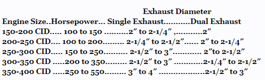
Header Gaskets – The Vortec exhaust ports are essentially square with rounded corners (1 5/16” x 1 5/16”, or 1.31” x 1.31”). With the Gen 1 heads, used Mr. Gasket #5917 (1.82”W x 1.50”H). That gasket will not seal at the top on the Vortecs with 1 5/8” (my) headers. Had to use Mr. Gasket #1404 (1.5”H x 1.5”W). The headers sealed without leaking using this gasket. The Dynomax are well made with a protruding lip on each pipe that is larger than the ID of the pipe itself which causes a good seal around a larger exhaust port. Other 1 5/8” headers lacking this lip may not seal at the top (again, look at the pic), and may require 2 different size gaskets for a good seal. 1 3/4” headers should seal with the appropriate gasket.
Head Gaskets – With Gen 1 heads, previously used FelPro 7733PT2 head gaskets (4.125” bore, 039” compressed thickness [8.700cc]) to ensure piston clearance with the .060 overbore. This is a good gasket because it can be removed without anything sticking. No scraping required. However, on the Vortec heads, wanted to reduce the quench area, so used GM# 10105117 (4.100 bore, .028” compressed thickness [5.94 cc]). No retorquing has been required.
Spark Plugs – With the Gen 1 heads, used Delco R45TS. The Vortecs require a longer reach plug for optimum spark, so used Champion RS12YC (.708” reach). With the Champions, if you don’t like the ‘12’ heat range, ‘09-14’ is available.
Intake Manifold – A Vortec style intake is required. Selected the Scoggin Dickey (SD) Vortec TPI Intake #3816 ($399 at the time). The Edelbrock intake is identical to the SD except for the Edelbrock logo, but costs $100 more. I was told by SD that they licensed their design to Edelbrock. Other literature supports this. The top of the TPI plenum (both front and back) is at the same height as previously with the stock TPI manifold. Note that you may need to make a couple of block-off plates if you’ve removed EGR, etc. (Edelbrock includes the plates, perhaps for the extra $100). Aluminum plate (1/8”+) works fine with RTV as a gasket. Also may need a few NPT plugs to fill holes depending you’re your hoses, accessories, etc.
Intake Gaskets – After a lot of research, chose to use the more expensive GM # 89017465 (approx $45 – Wow!). But am told by the round track guys that they are reusable a few times because of the raised rubber/neoprene seals around each port and water jacket. The Vortec intake seems to have more space between the bottom of the manifold and the front and back lifter valley ridges on the block than does the stock TPI manifold. Because of this, plan on using about 1/4”+ thick bead of RTV sealer to seal the front and back of the lifter valley – nothing on the gaskets themselves perhaps except right where they join the lifter valley.
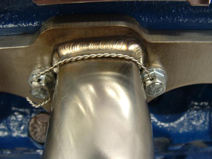
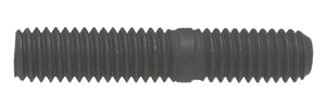
Intake Manifold Bolts & Installation – The old Gen 1 bolts won’t work. They are 3/8”-16 course thread bolts (16 bolts). Rather, must use 5/16”-18 x 1½” course thread bolts (8 bolts). I chose not to use the new GM self-bottoming bolts many recommend. These bolts, along with the intake gaskets above, were apparently released sometime after the release of the Vortec heads to solve all too many coolant leaks due to improper torquing and/or gasket deterioration. Because the fit of the intake is so critical, make four, 2” long threaded studs to aid in manifold installation. Bought 4, 2” long 3/8” bolts from Home Depot and cut off the heads with a Sawsall. Took 5 minutes. Screw the studs a few turns into the front and back holes on each side of each head, install the gaskets, lay down the RTV and carefully drop the intake manifold down using the studs for alignment and press/wiggle it around to seal the RTV. Remove the studs and install the bolts.
Snug all 8 bolts initially to 2 ft lb.{24 in/lb}, then second pass to 8 ft-lb.{96 in/lb} and last pass to 11-12 ft-lb {132-144 in/lb} Below is torque sequence; ‘o’ = bolt location:
7 1 / 3 5
o o / o o

Front / Rear

o o / o o
8 4 / 2 6
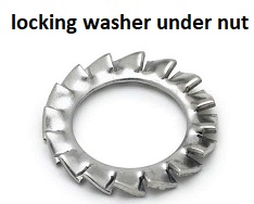
Head Bolts – The Vortec heads use the same number and length bolts as used with Gen 1 heads, but sometime later GM introduced a new design with a small flange under the bolt head. Since it’s thought best to not over re-use head bolts, I chose to use the new bolt design (GM complete bolt set #: 12495499). These bolts are pre-coated with a Teflon sealer, but very sparsely. Initially chose to not add additional sealer, but paid the price with a couple of the bottom (shortest) bolts not totally sealing. Fortunately no under-the-rocker-cover bolts leaked. So removed the leaking bolts one at a time, coated with Permatex 80632 Thread Sealant, retorqued and problem solved. Suggest coating all water jacket bolts with this or something similar.
Head Water Jacket Plugs – Like the Gen 1 heads, the Vortecs have a NPT threaded hole in the water jacket. If you have a thermocouple or something else that must install in one of these holes, you need to ensure that the headers will bolt on. Why? Because the top of the NPT hole is very close to the bottom of the header flange on the Vortecs. It’s 1/4+” lower on the Gen 1 heads. This is possibly because the exhaust manifold/headers are designed to mount 1/4” higher on the Vortec heads (again, see the pic). I only needed to use plugs in the holes, but because of the closeness of the top of the plug to the bottom of the header flange, a NPT plug with a hex head could not be used because the hex head is larger than the diameter of the NPT plug itself, and it interfered with the header flange. Naturally grinding was possible; but for me, a better solution was to use NPT plugs with a 4-sided head that is smaller than the diameter of the plug itself. These plugs worked without any grinding.
Head Accessory Bracket Mounting Holes – This was one of the principal reasons the more expensive Bowtie Vortecs were chosen over a cheaper aftermarket clone. If you review various posts and carefully question some of the Vortec clone manufacturers, some will admit that not all accessory brackets will fit without modification because of slightly varying GM bolt hole patterns over the years. Some of the head manufacturers pick one pattern and use it without regard to the others. My serpentine system moved from the Gen 1 heads to the Vortecs perfectly.
Push Rod Guide Plates – The Bowtie Vortecs assume you will be using self-aligning rocker arms. If you don’t, you’ll need pushrod guide plates [CompCams Flat Guide Plates (8) 5/16" #4808-8, approx $17]. Removed screw-in studs, installed guide plates and torqued studs to 35 ft/lb.
Pushrods – Pushrod length was measured with the Vortec heads installed using the old .039” gaskets (granted having an 0.011 compressed thickness difference between the old and new 0.028” gaskets to be used – this difference was determined to be immaterial). The measurements indicated that the stock length Gen 1 push rods were the proper length. The same is not true for some of the cloned Vortec heads. Because of the valves they use, many require at a minimum 0.100 longer pushrods for proper alignment of the valve train.
Head Condition When Received – Chose to order the heads from Jegs in case there was an issue requiring a return. There was. The heads come wrapped in an oil impregnated paper. However, when the heads were received, there were all manner of rust and pit marks on the machined surfaces, as if they had been stored in a very humid area for some time without any oil coating. Took pics, emailed pics to and called Jegs; and to their credit, they immediately issued a pick-up ticket and the heads were returned. Thanks Jegs! But when the second pair arrived (had to wait a few days because they were backordered so the second set was from a different manufacturing lot), they too were similar to the first but not as bad. Some minor filing and sanding took care of everything, but seems strange they would be in that condition. This is not Jegs fault. They buy all GM parts from a local Chevy dealer for resale as required by GM. Clearly the manufacturer is using less than adequate quality control and/or storage techniques. Go figure!
Valve Cover Height - One other issue to be aware of is that the top of the valve covers will sit higher with the Vortecs. How much, don’t know; but estimate 1/2”+. Just forgot to measure this before installation. It’s apparently due to the head’s raised upper lip for better oil control and leak reduction/elimination.
 
Last edited:
I was asked a rather interesting question, and that was will the headers the car uses need too be changed if the intake manifold design is changed.
I think that probably 99% of the guys I talk to have never grasped the concept that the two basic induction and exhaust system tuning are related!
I find it hard to understand why its so difficult for many guys to grasp the concept that its EXHAUST scavenging,
and the correctly matched cam timing, displacement, and compression ratio,
that has a huge effect on the cylinder fill efficiency and hence the resulting fuel/air ratio and burn efficiency,
that results in what can, be,(if the components are properly matched)
be a very noticeable increase in both the engine torque
( which is partly the result of higher cylinder pressures) and the engines, wider,
rpm band (mostly the result of more effective cylinder fill rates and more complete exhaust scavenging)
this can be easily demonstrated , as a restrictive exhaust can easily cost you more than 30% of an engines potential power that youll see with properly matched long tube headers and a 18"-22" collector extension.
the answer is that both the intake manifold design and the exhaust headers are both going to effect each others flow efficiency.
the problem is that most guys never think this through or ask how the two systems are related, and in most cases the guys buy a commercially made set of headers and bolt them on, and never give the choice they made a second thought!
Just as swapping from a dual plane intake with, lets say a 750-850 cfm, carb to a single plane intake with the same carb , on your typical chevy 350-406 SBC or 396-496 BBC, (after its re-tuned will have an effect on the cars power band,) a similar change in the exhaust can also change the engines effective power band!

I've always preferred the side exhaust header /muffler design on the C3 corvettes,and A.C. COBRAS,

acsidea1.jpg

acside2.jpg

acside3.jpg

if you were under the impression the side pipe muffler inserts were not restricting power try a dyno and careful engine re-tune with them removed, you may be amazed at the difference in power above 4000 rpm.
59165.jpg


sidespacer.jpg

of course side exhaust might be one reason Ive always prefered engineer boots and levi jeans
egnboot.jpg

https://www.cmrp.com/cone-calculator


,(like these picture's shows them) my B.I.L well remembers my 1968 BBC corvette (these are not my corvette's pictures) so he has installed those hooker side pipes on his 1974 BBC corvette

corvsider1.jpg

mitch2.jpg

index.php

on aluminum head's its almost alway's best to use studs to secure headers when you can,
as a stud has the threads full length engaged and very low stress , and significantly more surface area spreading the load,
than a bolt will ever allow,don,t forget too use anti-seize on the stud threads
shop around, the cost of the studs are not as high if you shop carefully, try a local bolt supply or hardware store.
I would point out that use of safety wired nuts and castle nuts with cotter pins, is in many applications, a separate,
and in my opinion better option ,
in that its both secure and easily removed if required, and less temp sensitive than chemical bonding agents.
yes obviously there are applications where loc-tite is the better option, and places where anti-seize and a castle nut and cotter pin or safety wire use is the best option.

http://garage.grumpysperformance.co...afety-wire-locking-fasteners.4306/#post-67524
axlenutM24.jpg

safe3.jpg

safe4.JPG


http://garage.grumpysperformance.com/index.php?threads/cotter-pins.4733/#post-12852


http://garage.grumpysperformance.com/index.php?threads/header-gaskets.1045/page-2#post-55418
https://www.jegs.com/p/ARP/ARP-Exhaust-Header-Studs/744890/10002/-1

11118322.jpg

https://www.fastenal.com/products/details/11118322;jsessionid=GFJnzZ+7+LoV4LCjDOCC8Gb5.b9408a77-0eb9-3dd2-aa63-3c743b855037?r=~|categoryl1:"609389 Fleet 9and Automotive"|~ ~|categoryl2:"609999 Tire 9and Wheel End Products"|~ ~|categoryl3:"609867 Double End Studs"|~


lockn1.jpg


lockn2.jpg

antiseize.jpg

headerstuds.jpg

I would strongly suggest BOTH stainless bolts studs and the use of ANTI SEIZE on the threads
arp-434-1301_w.jpg


studal3.jpg

studal2.jpg

studal1.jpg


119651.png

119651.jpg

119651.jpg

and on my 1968 corvette the car was slower by almost 2 tenths with the standard comp plus hooker under frame headers,when I tested them

( I tried them because they potentially saved weight ),
(obviously that was with the internal muffler inserts removed from the side pipes while racing)
but the under the car mufflers added too under the car headers total, weight,
are HEAVIER than the side pipes when the whole exhaust system is installed
if you do the required math calculations , you,ll find that most commercial headers are using primary tube length that are too short to be ideal,
as this simplifies manufacture and CLEARANCE ISSUES AND REDUCES MANUFACTURING COSTS.
(
the headers with side exhaust design, are closer too the ideal)

related info (you can use the linked info to do your applications calculations)

http://garage.grumpysperformance.com/index.php?threads/calculating-header-design.185/

http://garage.grumpysperformance.com/index.php?threads/calculating-required-exhaust-pipe-size.11552/


http://pypesexhaust.com/p-13194-dyno-tests.html


http://www.hotrod.com/articles/hppp-0312-headers-vs-manifolds/

http://garage.grumpysperformance.co...-between-shorty-and-full-length-headers.1303/

read related threads
http://garage.grumpysperformance.com/index.php?threads/spiral-mufflers-anyone.10365/#post-42725

http://garage.grumpysperformance.com/index.php?threads/c3-side-pipe-exhausts.793/#post-1150

http://garage.grumpysperformance.co...ders-that-work-with-sidepipes.2350/#post-6204

http://garage.grumpysperformance.co...lap-on-factory-headers.3155/page-2#post-66721
volumetric.gif

now obviously youll need to tune the car to max power with the engine running in the condition and set-up how you intend to race the car, simply because changing the exhaust scavenging efficiency will mandate changes in the carbs jetting , power valve etc. in most cases to maintain the almost ideal 12.6:1 fuel/air ratio over the intended power band and thats sure to change if you vary the exhaust scavenging efficiency or back pressure.
Stoichd.gif

pistonposition2.jpg

EXFLOWZ5.jpg

exhaustpressure.jpg

EXFLOWZ4.jpg


in the ideal exhaust system youll want to have less than .5

(thats 1/2 a PSI of back pressure) at the engines peak rpm
expsize.png


exarea.gif

http://www.exhaustvideos.com/faq/how-to-calculate-muffler-size-pipe-diameter/

http://www.mk5cortinaestate.co.uk/calculator5.php

fe008cfd.gif

3" o.d = 2.87" diam. inside--approximately 6.5 sq inches of area
2.75 o.d = 2.62"diam. inside--approximately 5.4 sq inches of area
2.5 o.d = 2.37" diam. inside--approximately 4.4 sq inches of area
2.25 o.d = 2.12" diam. inside--approximately 3.5 sq inches of area

pipechart.gif


expipesz.jpg

well worth reading

http://www.popularhotrodding.com/engine ... ndex1.html

http://garage.grumpysperformance.com/index.php?threads/exhaust-components.361/

0505phr_exh_12_z.jpg


tubingsizeversusarea1.jpg

http://garage.grumpysperformance.com/index.php?threads/calculating-required-exhaust-pipe-size.11552/

http://garage.grumpysperformance.co...-exhaust-pipe-diam-for-your-application.1730/

http://garage.grumpysperformance.com/index.php?threads/is-backpressure-hurting-your-combo.495/

http://garage.grumpysperformance.com/index.php?threads/building-an-exhaust-system-for-your-car.1166/

http://garage.grumpysperformance.co...-calculators-and-basic-math.10705/#post-72061

http://www.wallaceracing.com/Calculators.htm


Last edited:
I wonder how many guys realize that the power and torque numbers in an intake manifold test like this thread above has could be markedly different if the headers on the car being tested were optimized to maximize the intakes power curve!
I discussed some of those engine requirements in this thread and its links
what you,ll rapidly come to realize is that an all out max effort engine will require about a 4500 feet per minute piston speed , a connecting rod as close to 1.9:1 length too stroke ratio, (minimum) with a 6" connecting rod in the common 302-327-350 SBC being preferred , and the 6.385" connecting rods used in the 427,454,and 496 BBC engines and about 13:1 compression.
youll also need very good cylinder heads with port and runner cross sectional areas matching the application.
obviously we were using higher octane race fuel and a solid lifter roller valve train, roller rockers, ported heads and intake manifolds, in most cases, this obviously requires a matching drive train gearing and while you might make far better than average power per cubic inch in the 1.5 or greater horse power per cubic inch range you also build an engine that's not ideal as a daily driver or for decent fuel economy.
but if you stuff an engine built like that in a 2800 lb vega with a 4.11:1-4.56:1 rear gear, and a manual transmission with a 35 lb billet flywheel, add some decent slicks and set up the suspension correctly you can run impressive times, and have a lot of fun.

http://garage.grumpysperformance.com/index.php?threads/carb-intake-test.58/

play with the software dyno programs and compare results
http://garage.grumpysperformance.com/index.php?threads/virtual-dyno-software.2301/#post-53646

http://garage.grumpysperformance.co...k-top-dyno-as-a-tuning-tool.10939/#post-48072

obviously if youve been reading the links and related threads you know the ideal matched headers size and length can be accurately calculated
http://garage.grumpysperformance.com/index.php?threads/calculating-header-design.185/

http://garage.grumpysperformance.com/index.php?threads/building-custom-headers.961/

http://www.wallaceracing.com/header_length.php

http://garage.grumpysperformance.co...lap-on-factory-headers.3155/page-2#post-63298

matching intake port size and runner length can also be calculated
http://garage.grumpysperformance.com/index.php?threads/port-speeds-and-area.333/

http://garage.grumpysperformance.co...gine-to-match-the-cam-specs.11764/#post-55651

http://users.erols.com/srweiss/calccsa.htm

http://www.wallaceracing.com/intake-runner-length.php

http://www.wallaceracing.com/ca-calc.php

http://users.erols.com/srweiss/calcplv.htm

http://users.erols.com/srweiss/calcacsa.htm

as can the cams that match the intended power band and rpm range
http://garage.grumpysperformance.co...t-for-specific-applications.10162/#post-40007

http://garage.grumpysperformance.co...ing-parts-and-a-logical-plan.7722/#post-51341

http://garage.grumpysperformance.com/index.php?threads/a-few-calculator-links.7108/#post-27382

http://garage.grumpysperformance.com/index.php?threads/calculating-overlap-and-lsa-or-lca-etc.480/

craneq2.gif
camcomp.jpg

Duration_v_RPM-Range_wIntakeManifold01.jpg

0607phr_11_z+camshaft_basics+lobe_centerline_angle_determination_chart.jpg

dcr.jpg


LiftCurveAread.gif

porting+valve_area.jpg


volumetric.gif

pistonposition2a.jpg

exhaustpressure.jpg


http://www.wallaceracing.com/dragcalcquarter.php

http://www.wallaceracing.com/calc-gear-tire-rpm-mph.php

http://www.wallaceracing.com/Calculators.htm

http://garage.grumpysperformance.com/index.php?threads/another-496bbc.5123/

http://garage.grumpysperformance.co...ouple-known-effective-sbc-engine-combos.7028/

http://garage.grumpysperformance.co...sbc-vs-383-sbc-dyno-results.10210/#post-40509

http://garage.grumpysperformance.com/index.php?threads/the-new-215cc-vortec-heads.266/#post-35948

http://garage.grumpysperformance.com/index.php?threads/long-rod-302.12866/#post-66748
 
Last edited:
Back
Top