Porting the Edelbrock Pro Flow XT 7137

Thanks Grumpy,

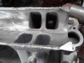
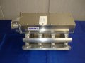
The outside appearance of the finished manifold will be altered from the original. The sand cast sides of the plenum will be replaced with flat bar. I'm going to have 3" flat bar bent to match the angle from the vertical walls towards the horizontal roof. This will change the appearance. As you were with your HSR, I'm more concerned with performance and fit than I am with appearance. Still, for the finished product, having neat professional looking welds will make a big difference.
 
I went by the welders yesterday. They had me come down to review the progress, let them know if they needed to add more material. I did have them add a little more in the lowest corner, where they had cut too deep originally. The work so far looked good. Runner #7, which was cut into looks normal now. They should be finished with it today. Then it will go to the machinist for flat milling of the plenum wall mating surfaces. The welders have an old iron worker machine and they can do the bending on the side wall flat bar for me. In fact they had some material about .1875 thick that looks like it will work well.

The welder gave me another idea too, when he asked if I was going to round out the side walls into an oval shaped plenum. At first I though no just flat walls. Later, I thought it may not be such a bad idea. I'm redesigning the plenum from a single 90mm throttle opening to a 58mm dual throttle opening. From the time I made this decision, I've been expecting to have to pinch the large dual throttle bores down to enter the narrow plenum. Maybe, I don't have to pinch them down that much. Rounded side walls would mean more clearance for the throttle openings. The only drawback is how to mount the throttle bracket. It needs a flat area on the left plenum wall about 3 inches back from the TB flange. However, if we can carefully lay out the mounting points we should be able to attach threaded bosses to the rounded side walls.

So, could be that this project has just expanded beyond its original scope. The old welder asked yesterday if I planned to finish this thing some time this year. Sure, I said.......
 
Thanks Grumpy. Things are starting to move that way. Since this is a redesign, rather than just adapting a different TB, we are going to be making some changes to the plenum.

The walls will be cut from 3" aluminum pipe to create an oval shape, more fitting to the dual throttle. times. Welding the throttle adapter in place fits perfectly into the plan.

In fact, since we're welding the adapter in place, why not just cut away the existing TB flange and replace it with the new dual TB flange. We can extend the rounded walls to meet the new flange.

We're reusing the plenum top. It will be shorter than the walls but the space can be filled with plate. I'll lay out this concept and run it past the welder and machinist.
 
Here are today's photos. I'm very pleased with the welder's latest work. There is still one small area that will need some fill. That can wait until the sides are ready to be welded in place. I cut the original throttle flange down level with the sides of the plenum floor. The machinist will flat mill the second angle on each side out to what was originally the TB mounting surface and then flat mill the sides to create the mating surfaces for the new plenum walls. At that point, we'll decide whether to make the walls from pipe or flat bar. It will depend on fit and how the angles come together. One key factor is providing for the dual 58mm throttle in the plenum design. The new throttle flange will be welded on the bottom to whats left of the original flange. Then, the new sides and roof will be mated to the new flange.
 

Attachments

  • 20180214_153232.jpg
    20180214_153232.jpg
    33 KB · Views: 7
  • 20180214_153255.jpg
    20180214_153255.jpg
    34.3 KB · Views: 6
thanks for posting the up-dated pictures of the custom intake builds progress
 
Hi Grumpy. It's starting to get pretty exciting now. Once the bottom is milled and ready for walls, well sit down and decide on the exact design of the new plenum. The TB flange will be much simpler now since its no longer an adapter that has to attach to two different bolt patterns and opening shapes.

I still have four runners to port. I'll get that done as soon as the flat milling of the plenum is finished. I'll also complete the fillets at the runner entries then. Before the walls and throttle flange go on.
 
spend the time and effort to get the runner entrances and exits, on those runners,
exactly the way you want them, because you don,t want to have any nagging mental,
second guess work after its re-assembled, and re-welded, and,
obviously , do a bit of checking and test fitting,
make sure the assembled,custom intake manifold
height /and length, allows,

the distributor,.
fuel rails,
injectors,

any sensors, heat, vacuum
any IAC/ TPS/MAT sensor or valve

t-stat,water neck housing
throttle linkage,
and
hood clearance
required clearances
 
Yes Sir! I need to spend some time on the runner entrances to get the fillets right. Once this first stage of machine work is finished, I'll get back to work porting bank 1 and getting those fillets completed.

Clearance to the distributor won't have changed since the rear plenum wall hasn't moved. The XT provides clearance for the small cap HEI that I have already. Things I will be sure to have right before final assembly are 1. Clearance to the T-stat housing for the new TB flange. I'll be sure to check that before I get the new flange welded in place. I'm going to use the housing TPIS sells for the Miniram. One of the tasks of the machinist will be trimming the lower portion of the new TB flange to provide clearance. 2. Hood clearance for the throttle body and roof height of the plenum. While the 87 Camaro has a little extra space for plenum height, I want to be able to use my existing strut brace if practical. At the same time, if getting the plenum design where I want it means I have to either replace or modify the strut tower brace, that's what I'll do. Throttle body clearance is part of why I went with the dual TB instead of the single 90mm. It would be a shame to have gone to all this trouble to end up with hood clearance issues. Before I begin assembly of the plenum, including placement of the new TB flange, I'll spend some time with the car here at the shop measuring the heights of the existing TPI plenum and clearances to the hood from the TB as installed. The TPI plenum noses down in the front, which in fact places it at a slight downward angle compared to the high flow air intake housing that I built. I think that the XT's plenum will work best with the TB mounted level vs. at an angle. Getting the height correct for clearance to the T-stat housing and for hood clearance will be critical. Having the TB align correctly with the air intake will be a bonus.

Going to deliver the XT to the machinist on Sunday. Exciting stuff!
 
I enjoy how you seem to be considering all the angles, pun intended! Are you keeping an
eye on plenum volume, are you shooting to keep it the same?

Wow, most certainly a labor of love!!!+
 
Plenum volume has been at the forefront of my thinking. From the start, I determined that the 190cid as cast plenum volume was on the small side for a 383 and especially for a 400+ cid motor. The smallish plenum was targeted toward throttle response and midrange torque along with the narrow runner exits. The balance between throttle response and great top end performance is a key issue. The finished runners are definitely capable of flowing alot more which would support more top end power, but as has been brought up already, we don't drive top end HP, we drive torque. Therefore, I will keep plenum volume right about 200cid for now. It can always be adjusted later if performance results indicate that it would be helpful. At some point, we are likely to run this thing through a fluid dynamics modeling program to see what it tells us.

No news from my machinist friend Travis yet. I've got a feeling he's probably making plans to use the 5 axis CNC mill he has at work to do some magic, perhaps even perfect the fillets. I have finally reached a decision, albeit a flexible decision, on what to do with the plenum walls and top. In my conversation with Travis last weekend, he echoed my own concerns on working with pipe for the plenum walls. We agreed then that we would use flat aluminum for the walls and bend it as needed to produce the shape I wanted. Travis brought back up the idea of a removable top. I had thought about this early on but abandoned the idea because of logistical issues. Once again this time around, I came back to the same problems. How to make the throttle bracket mounting work with a seam along the mid line of the plenum. Sealing is an even bigger issue with the various surfaces and angles that have to come together.

After some days of consideration and I'll admit, stealing ideas from folks like Hogan's, I arrived at a solution for the removable top that should solve all of the logistic issues. However, I still wasn't solid on just how to do the top panel. I didn't want a square box because of volume and air motion control concerns. However, any bends in the removable top panel would make fitment more of a problem. Last night, I finally came to a solution. The panel will be flat, cut from something like 5/16" plate. The edges of the plenum, where the panel attaches will have 3/8" to 1/2"rails welded in with threaded holes for the top panel attaching screws. Those rails will be about 3/4" tall and profiled at an angle to control volume and produce the internal plenum shape that I want.

Picture something like this piece from Hogan's.
 

Attachments

  • 100329d1184091055-hogan-s-racing-manifolds-ls7-intake-hogan.jpg
    100329d1184091055-hogan-s-racing-manifolds-ls7-intake-hogan.jpg
    86.5 KB · Views: 9
yeah its always a project in flux , but with thought and research it tends to get improved.
 
I wanted a Hogans Sheet metal intake in the past for my 87 C4 Corvette Real Bad.
About 2009-2010.
Cost was $10,000 cash.
Found one used for $5000.
Had the money but chose not to follow through.
Looking back I am glad did not buy it.
Build a Killer Big Block Chevy and stomp all with a Carburetor.
 
Plenum volume has been at the forefront of my thinking. From the start, I determined that the 190cid as cast plenum
volume was on the small side for a 383 and especially for a 400+ cid motor.
So how did you determine that it's too small and therefore the size that you need. If you have calcs,
please show them.


At some point, we are likely to run this thing through a fluid dynamics modeling
program to see what it tells us.
That software cannot be cheap, so what connection do you have? What is the software called?

For the software to do it's thing with some accuracy, won't you need a 3D model of the intake manifold?

When you get done, you can be our resident expert !!! This is very cool what you are doing, I love
all the planning you are doing. It's very interesting.
 
If you are going to fabricate the removable top as you described above, then an o-ring groove can be cut either into the rails or the top plate to make sealing it very easy. Otherwise you would have to make your own custom paper gaskets from gasket material and the gasket would probably get sucked in between the bolt holes.
 
No progress to report. The machinist has the XT and he hasn't sent me any updates yet, even though I've been pestering him constantly with the ideas I've come up with while he's had it. I decided about Wednesday to leave him alone and stop stuffing his inbox with anymore emails. He promised update photos as he begins to make progress. I trust he'll do as he said he would, once he gets things ready.

He hinted at using the 5 axis machine, which would mean first mapping the piece in whatever cad program they're using. I have a sense it may be solidworks. It seems like he mentioned that name. Since he's not charging me anything for his time, I feel like I should be patient, as hard as that is for me. While I'm not going to push him on it, his using the 5 axis CNC would save me numerous hours and likely frustration finishing the runner fillets. Any results I might end up with, working the fillets by hand, would pale in comparison to what he can do with a radius bit in the 5 axis mill.

Sealing the plenum is the key concern in using a removable top. So much simpler to just weld it all up solid. Following the Hogan's design, we would flat mill the top once the rails are welded in place, creating a solid 5/8" wide rail around the plenum top. Ball milling an o-ring groove into this machined rail will provide for sealing.
 
I don't know what he has. He mentioned mapping the plenum walls and floor, also mapping the original plenum top cutoff and transferring the data into his CAD software for use in design of the new plenum. I don't know if that is necessary since the plenum is being changed so much. The design I've pretty much settled on is really very simple and should be a snap to produce.

As far as mapping the runners is concerned, I'm getting off track anyway. This is a hand ported manifold. One bank is already finished aside from the fillets. The other side I plan to do the same way, using calipers to measure and produce the most even results I can. If not perfect, it will be vastly improved. If we do more of these in the future, CNC may come more into play then.

Mapping the runner entries may be useful for cutting the fillets on the 5 axis mill. I can do the fillets by hand. It will just take more time and the results will be less precise.
 
Im sorry Indycars. I missed one of your posts. You asked about 3d mapping the manifold for use in fluid dynamics modeling and what software we might use. We haven't gotten that far. It only came up briefly in our last meeting. We may decide to go there, even just for fun. I sense that Travis has access to the software.

I base my thinking on plenum size around 1/2 - 2/3 engine displacement for an engine producing peak power between 6,000 and 6,800 rpm.

There doesn't seem to be any hard rule on plenum volume for the dry flow intake.
We see velocity stack setups that work just fine. Smaller plenums seem to better support pressure wave tuning and if matched correctly to the cam, displacement, and total runner volume will produce a better torque curve at lower revs. The smaller plenum becomes a restriction at higher rpm. Since we're porting the runners for increased flow and to move the torque up 500rpm, I feel like a bit more plenum volume will be good. The increase will be about 15%. From 190 to around 220cid. I'll have more exact figures when i sit down and draw up the final plenum design. The throttle flange alone is adding about 15cid.

The race manifold builders I've researched like plenum volume around 3/4 of engine displacement for fuel injected motors making power to 9,000rpm.
 
Back
Top