leaking injectors or any source of a constantly overly rich, fuel/air mix can and will eventually screw up your O2 sensors, try hard to tune your engine to stay in the 12:1-15:1 fuel air ratio range, the closer to 14.7:1 , and the less contaminates like coolant or moisture, the better the sensor likes it, and the longer its likely to last
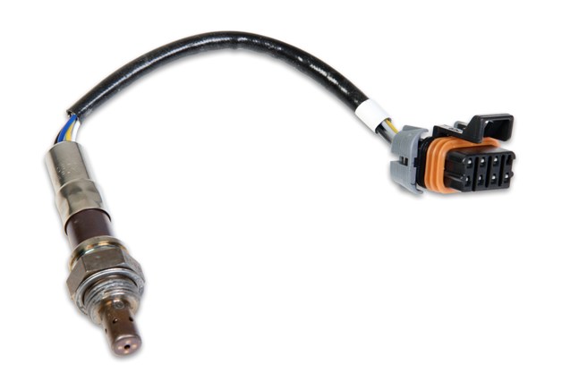
IF you want to upgrade the current one wire oxygen sensor on the earlier c4 corvettes to a later more effective three wire oxygen heated sensor...
RUST,AGE,MOISTURE, ACIDS, COOLANT IN THE EXHAUST,ALSO TEND TO LIMIT THE SENSOR LIFE EXPECTANCY
excessive use of injector cleaner, leaded fuels leave clogging residues, or water absorbing fuel additives, added to the fuel or coolant seeping into the exhaust or an excessively rich a/f ratio will eventually kill an O2 sensor
"Water absorbing fuel additives such as alcohols....or use of fuel drying additives, that contain alcohol as most do, tend to damage sensors"
I'm NOT sure if its the alcohol or something ELSE in the cans of products similar to (DRY GAS) and similar additives LIKE injector cleaners but its been depressingly common to see the O2 sensors quit after awhile if that type of products been used frequently, Ive got brother-in-laws and friends that regularly dump that stuff in their tanks and we replaced O2 sensors almost yearly until I got them to just change the oil and all the filters regularly and stop dumping the latest wonder additive in the tank every other fill up
Its not a good idea to add injector cleaner formulas to the fuel on almost every fill up.
but ID also point out that alcohols HYDROSCOPIC (SPELLING??) IT tends to absorb moisture and the combo of excess moisture, heat and exhaust tends to eat sensors, keep in mind a mild sulfuric acid is formed from exhaust gases and moisture.
keep in mind O2 sensors need to run fairly hot and only provide data to the CPU over a limited fuel/air ratio range thats NEAR 14.7:1
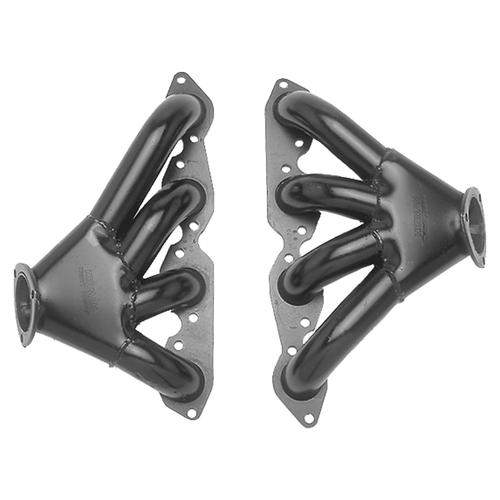
most decent headers have 32"-39" long primairy header pipes so the collector is at least that distance from the exhaust port
18" from the exhaust port makes sense with something like shorty headers
make sure your cars battery is unplugged for several minutes after any defective oxygen sensor replacement, to reset volatile memory, and if possible reset any of the trouble codes, showing a defective o2 sensor code present, it is a given that the cars trouble code memory contains bad fuel trim data, until its reset.
easier to weld thicker bung with base contoured to fit collector
https://www.summitracing.com/search...-type/weld-in-bungs-and-fittings?fr=part-type
but you would only read the exhaust from a single cylinder on true performance headers at 18" from the exhaust port
thus collectors for performance headers have sensor bungs welded in the collector where they are located in the flow of exhaust from all the cylinders on that bank, but this presents a potential problem, because all oxygen sensors work best at higher temps (the reason 18" from the exhaust port was advised) so its best to select the HEATED OXYGEN SENSORS in that application
single wire sensors should be located close to the exhaust port

article on mounting bungs on collectors
http://www.classicchevy.com/assets/pdf/classicchevy/18-281, TECH.pdf
the later multi wire heated sensors are much more tolerant as to actual location and work fine in header collectors

http://www.superchevy.com/how-to/additi ... ult-codes/
viewtopic.php?f=56&t=3049&p=8053&hilit=oxygen+sensors#p8053
read the links as they contain a good deal of info
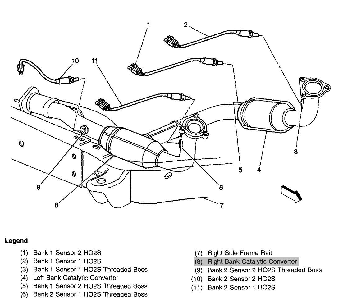
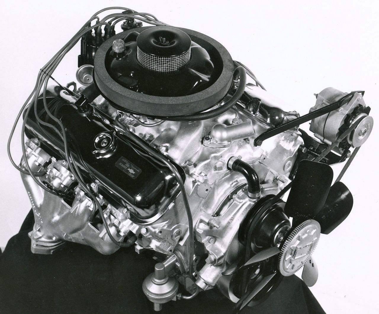
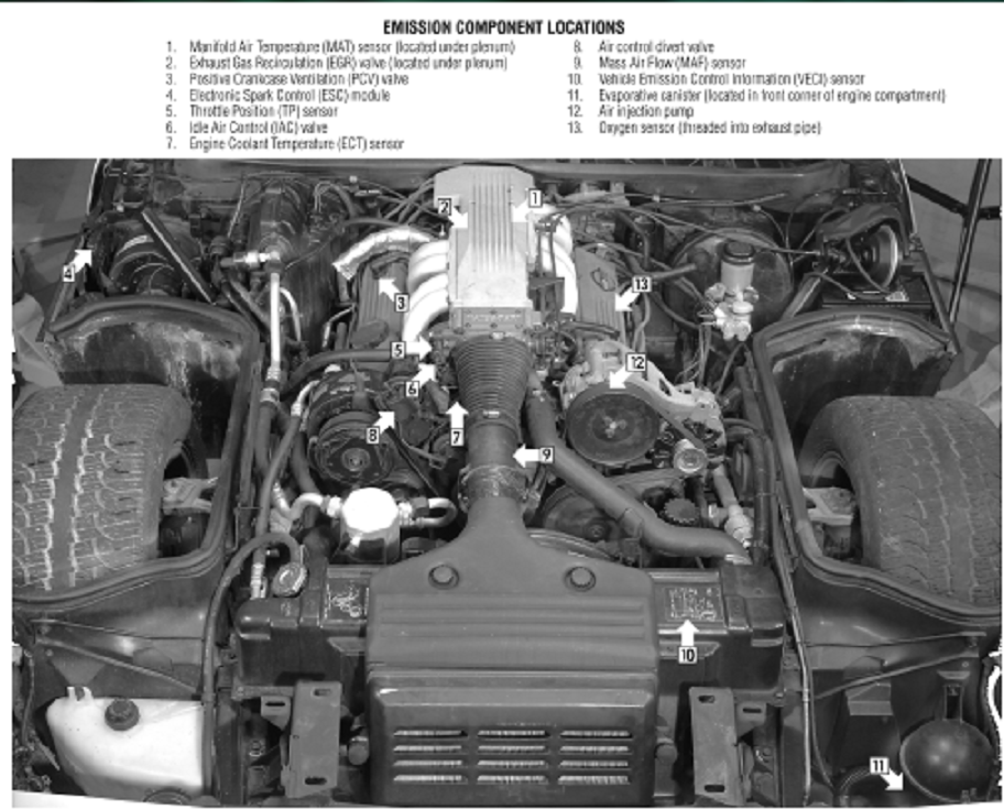
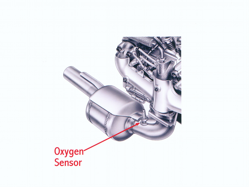
early L98 typically run 1 oxygen sensor in front the common catalytic converter.
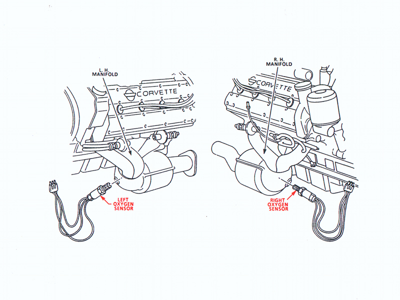
LT1 and LT4 run Four (4) oxygen sensors.
One in front of each catalytic converter.
One behind each catalytic converter.
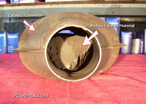
this defective cat is very common on older c4 corvettes
viewtopic.php?f=56&t=495
http://garage.grumpysperformance.com/index.php?threads/so-you-failed-emmision-testing.3522/
http://auto.howstuffworks.com/question257.htm
http://www.picoauto.com/applications/lambda-sensor.html
http://mr2.com/TEXT/O2_Sensor.html
http://www.scirocco.org/tech/misc/afgauge/af.html
http://en.wikipedia.org/wiki/Oxygen_sensor
http://www.casperselectronics.com/store ... cts_id=698
http://www.asashop.org/autoinc/june/Tech2tech.htm
http://www.aa1car.com/library/o2sensor.htm
http://www.asashop.org/autoinc/dec2002/mech.htm
http://www.wellsmfgcorp.com/pdf/Counterpoint2_3.pdf
http://www.pelicanparts.com/bmw/techart ... sensor.htm
http://www.engine-light-help.com/oxygen ... codes.html
http://www.walkerproducts.com/faqs_o2.html
http://www.aa1car.com/library/wraf.htm
http://auto.howstuffworks.com/framed.ht ... ensor.html
_________http://en.wikipedia.org/wiki/Stoichometric_________

Bosch LSU4.2 WBO2 Sensor
http://www.boschautoparts.com/OxygenSen ... nsors.aspx
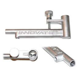
if yours is defective or missing why not just weld on a bung on the header or exhaust pipe and install the correct 02 sensor?
http://forum.grumpysperformance.com/viewtopic.php?f=56&t=3049&hilit=oxygen+sensor
http://www.ecklerscorvette.com/corvette-exhaust-oxygen-sensor-1982-1986.html

NTK WBO2 Sensor
http://www.ngksparkplugs.com/products/o ... p?mode=nml
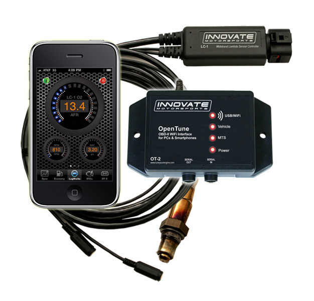
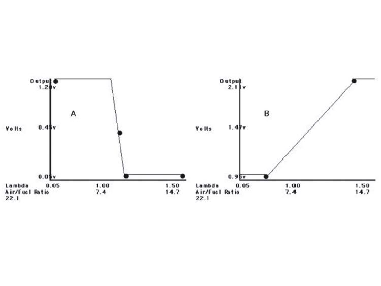
it helps if you understand that oxygen sensors do not measure your true fuel air ratio,entering the engine, but instead measure the remaining oxygen content of the burnt exhaust gases,and there are both narrow and wide band sensors
You cannot turn OFF the rear 02s, only turn off their error codes from tripping.
Bad idea not using the rears as they also are used by the PCM to compute the fuel trims
racingvette posted this additional info
"As per GM :
The rear oxygen sensor, located after the catalyst, is used for fuel trim corrections on OBD-II vehicles. By virtue of its location, the rear sensor is generally protected from high temperatures and much of the contamination that affects the front oxygen sensors.
In addition, the rear sensor sees exhaust gases that are equilibrated – they have already been converted by the catalyst so that there is very little residual oxygen.
This allows the rear sensor to respond to much smaller changes in exhaust gas oxygen content. In turn, it then possible for the rear sensor voltage to remain near the 0.45 volt switchpoint.
This characteristic allows the rear sensor to be used for fuel control. Under steady rpm and load conditions, the short term fuel trim bias can be adjusted so that the rear sensor voltage is maintained near the 0.45 volt switchpoint.
This ensures that the catalyst is getting a stoichiometric exhaust gas mixture, despite any shift in the front sensor switchpoint.
The rear fuel trim corrections are learned in KAM (Keep Alive Memory).
Internally, this system is known as Fore Aft Oxygen Sensor Control (FAOSC). Note that FAOSC learns and reacts very slowly because the catalyst, with its large/slow oxygen storage and release characteristic, is part of the control loop. Also, this system cannot be used with a "y-pipe" exhaust where a single rear sensor would try to adjust dual front sensors.
Rear O2s if you will are a fine tune of the commanded fuel flow but are very much part of the model used in the PCM's math to correct AFR for closed loop
This means running no rear O2s or Simms will effect how the PCM computes what the fuel trims are.
There is 2 02 wiring connectors per side on frame rail
Each side has 2 different shaped wiring connectors and the front and rear 02s have a matching connector shape so they cannot be connected in wrong UNLESS someone has hacked the 02 wires and used the wrong connector or incorrect wiring order.
Look at the stock 02 sensors and it will be clear which shape they have and match to the main wiring harness.
If you are wrongly using the rear 02 connectors for the fronts then they are on the wrong side of engine as the right rear connector is for the left rear 02 and same for left side is for right rear 02.
Using a OBD-II scanner would quickly tell you the state of the 02 sensors and wacked fuel trims would point to 02s in the wrong placement"
one factor I seldom seen mentioned is the fact that fuel must be atomized and mixed with air in a vapor form to burn effectively, and that oxygen sensors measure the remaining un-used oxygen in the exhaust gases, NOT the REMAINING FUEL CONTENT and the difference is important as your tail pipe could be dripping raw fuel while the oxygen sensor reads a LEAN REMAINING HIGH OXYGEN CONTENT in the exhaust gases, being measured by the oxygen sensor data, if the fuel was poorly atomized and far less that 100% of the fuel flow passing thru the cylinders is being burnt efficiently.
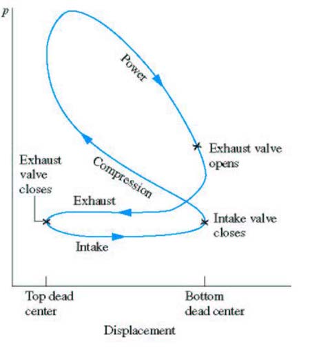
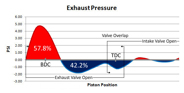
a highly effective exhaust header scavenging the cylinder matched to a cam with significant over lap can quite easily promote that result if the fuel is not being efficiently atomized, especially in a fairly cool combustion chamber.

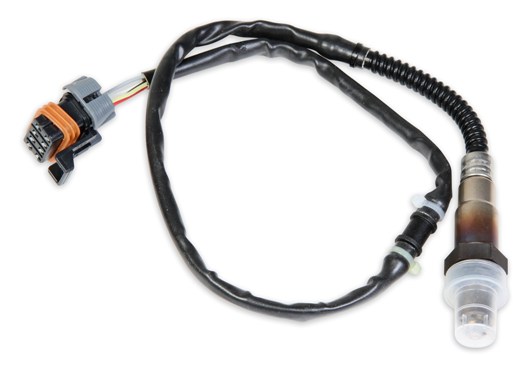
IF you want to upgrade the current one wire oxygen sensor on the earlier c4 corvettes to a later more effective three wire oxygen heated sensor...
catalytic converterFor wiring I found this, I also used as a guide for what one to buy:
http://sethirdgen.org/HO2S.htm
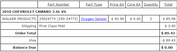
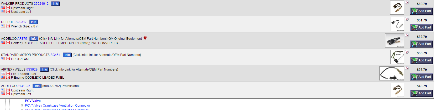
http://www.rockauto.com/en/catalog/...l+v8,1041398,emission,oxygen+(o2)+sensor,5132
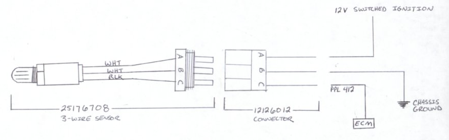
3-wire Heated Oxygen Sensor: 25176708
3-wire Weatherpack Connector: 12126012
You will notice the sensor has two white wires and one black. The white wires can be interchanged, polarity does not matter. One must go to a good clean ground, either on the body or the engine block, and the other must go to a 12V switched ignition source (Power w/ the key in the "RUN" position). Many people tap into the MAF power wires if you have a MAF sensor, but any "hot" wire in RUN only will work. It can't be HOT all the time, or you will drain your battery.
The black wire goes to the stock PURPLE wire that originally went to your one-wire Oxygen sensor. This is the signal wire to the ECM.
YOU NEED A MULTI METER

RUST,AGE,MOISTURE, ACIDS, COOLANT IN THE EXHAUST,ALSO TEND TO LIMIT THE SENSOR LIFE EXPECTANCY
excessive use of injector cleaner, leaded fuels leave clogging residues, or water absorbing fuel additives, added to the fuel or coolant seeping into the exhaust or an excessively rich a/f ratio will eventually kill an O2 sensor
"Water absorbing fuel additives such as alcohols....or use of fuel drying additives, that contain alcohol as most do, tend to damage sensors"
I'm NOT sure if its the alcohol or something ELSE in the cans of products similar to (DRY GAS) and similar additives LIKE injector cleaners but its been depressingly common to see the O2 sensors quit after awhile if that type of products been used frequently, Ive got brother-in-laws and friends that regularly dump that stuff in their tanks and we replaced O2 sensors almost yearly until I got them to just change the oil and all the filters regularly and stop dumping the latest wonder additive in the tank every other fill up
Its not a good idea to add injector cleaner formulas to the fuel on almost every fill up.
but ID also point out that alcohols HYDROSCOPIC (SPELLING??) IT tends to absorb moisture and the combo of excess moisture, heat and exhaust tends to eat sensors, keep in mind a mild sulfuric acid is formed from exhaust gases and moisture.
keep in mind O2 sensors need to run fairly hot and only provide data to the CPU over a limited fuel/air ratio range thats NEAR 14.7:1
most decent headers have 32"-39" long primairy header pipes so the collector is at least that distance from the exhaust port
18" from the exhaust port makes sense with something like shorty headers
make sure your cars battery is unplugged for several minutes after any defective oxygen sensor replacement, to reset volatile memory, and if possible reset any of the trouble codes, showing a defective o2 sensor code present, it is a given that the cars trouble code memory contains bad fuel trim data, until its reset.
easier to weld thicker bung with base contoured to fit collector
https://www.summitracing.com/search...-type/weld-in-bungs-and-fittings?fr=part-type
but you would only read the exhaust from a single cylinder on true performance headers at 18" from the exhaust port
thus collectors for performance headers have sensor bungs welded in the collector where they are located in the flow of exhaust from all the cylinders on that bank, but this presents a potential problem, because all oxygen sensors work best at higher temps (the reason 18" from the exhaust port was advised) so its best to select the HEATED OXYGEN SENSORS in that application
single wire sensors should be located close to the exhaust port
article on mounting bungs on collectors
http://www.classicchevy.com/assets/pdf/classicchevy/18-281, TECH.pdf
the later multi wire heated sensors are much more tolerant as to actual location and work fine in header collectors
http://www.superchevy.com/how-to/additi ... ult-codes/
viewtopic.php?f=56&t=3049&p=8053&hilit=oxygen+sensors#p8053
read the links as they contain a good deal of info
early L98 typically run 1 oxygen sensor in front the common catalytic converter.
LT1 and LT4 run Four (4) oxygen sensors.
One in front of each catalytic converter.
One behind each catalytic converter.
this defective cat is very common on older c4 corvettes
viewtopic.php?f=56&t=495
http://garage.grumpysperformance.com/index.php?threads/so-you-failed-emmision-testing.3522/
http://auto.howstuffworks.com/question257.htm
http://www.picoauto.com/applications/lambda-sensor.html
http://mr2.com/TEXT/O2_Sensor.html
http://www.scirocco.org/tech/misc/afgauge/af.html
http://en.wikipedia.org/wiki/Oxygen_sensor
http://www.casperselectronics.com/store ... cts_id=698
http://www.asashop.org/autoinc/june/Tech2tech.htm
http://www.aa1car.com/library/o2sensor.htm
http://www.asashop.org/autoinc/dec2002/mech.htm
http://www.wellsmfgcorp.com/pdf/Counterpoint2_3.pdf
http://www.pelicanparts.com/bmw/techart ... sensor.htm
http://www.engine-light-help.com/oxygen ... codes.html
http://www.walkerproducts.com/faqs_o2.html
http://www.aa1car.com/library/wraf.htm
http://auto.howstuffworks.com/framed.ht ... ensor.html
_________http://en.wikipedia.org/wiki/Stoichometric_________
Bosch LSU4.2 WBO2 Sensor
http://www.boschautoparts.com/OxygenSen ... nsors.aspx
if yours is defective or missing why not just weld on a bung on the header or exhaust pipe and install the correct 02 sensor?
http://forum.grumpysperformance.com/viewtopic.php?f=56&t=3049&hilit=oxygen+sensor
http://www.ecklerscorvette.com/corvette-exhaust-oxygen-sensor-1982-1986.html
NTK WBO2 Sensor
http://www.ngksparkplugs.com/products/o ... p?mode=nml
it helps if you understand that oxygen sensors do not measure your true fuel air ratio,entering the engine, but instead measure the remaining oxygen content of the burnt exhaust gases,and there are both narrow and wide band sensors
You cannot turn OFF the rear 02s, only turn off their error codes from tripping.
Bad idea not using the rears as they also are used by the PCM to compute the fuel trims
racingvette posted this additional info
"As per GM :
The rear oxygen sensor, located after the catalyst, is used for fuel trim corrections on OBD-II vehicles. By virtue of its location, the rear sensor is generally protected from high temperatures and much of the contamination that affects the front oxygen sensors.
In addition, the rear sensor sees exhaust gases that are equilibrated – they have already been converted by the catalyst so that there is very little residual oxygen.
This allows the rear sensor to respond to much smaller changes in exhaust gas oxygen content. In turn, it then possible for the rear sensor voltage to remain near the 0.45 volt switchpoint.
This characteristic allows the rear sensor to be used for fuel control. Under steady rpm and load conditions, the short term fuel trim bias can be adjusted so that the rear sensor voltage is maintained near the 0.45 volt switchpoint.
This ensures that the catalyst is getting a stoichiometric exhaust gas mixture, despite any shift in the front sensor switchpoint.
The rear fuel trim corrections are learned in KAM (Keep Alive Memory).
Internally, this system is known as Fore Aft Oxygen Sensor Control (FAOSC). Note that FAOSC learns and reacts very slowly because the catalyst, with its large/slow oxygen storage and release characteristic, is part of the control loop. Also, this system cannot be used with a "y-pipe" exhaust where a single rear sensor would try to adjust dual front sensors.
Rear O2s if you will are a fine tune of the commanded fuel flow but are very much part of the model used in the PCM's math to correct AFR for closed loop
This means running no rear O2s or Simms will effect how the PCM computes what the fuel trims are.
There is 2 02 wiring connectors per side on frame rail
Each side has 2 different shaped wiring connectors and the front and rear 02s have a matching connector shape so they cannot be connected in wrong UNLESS someone has hacked the 02 wires and used the wrong connector or incorrect wiring order.
Look at the stock 02 sensors and it will be clear which shape they have and match to the main wiring harness.
If you are wrongly using the rear 02 connectors for the fronts then they are on the wrong side of engine as the right rear connector is for the left rear 02 and same for left side is for right rear 02.
Using a OBD-II scanner would quickly tell you the state of the 02 sensors and wacked fuel trims would point to 02s in the wrong placement"
one factor I seldom seen mentioned is the fact that fuel must be atomized and mixed with air in a vapor form to burn effectively, and that oxygen sensors measure the remaining un-used oxygen in the exhaust gases, NOT the REMAINING FUEL CONTENT and the difference is important as your tail pipe could be dripping raw fuel while the oxygen sensor reads a LEAN REMAINING HIGH OXYGEN CONTENT in the exhaust gases, being measured by the oxygen sensor data, if the fuel was poorly atomized and far less that 100% of the fuel flow passing thru the cylinders is being burnt efficiently.
a highly effective exhaust header scavenging the cylinder matched to a cam with significant over lap can quite easily promote that result if the fuel is not being efficiently atomized, especially in a fairly cool combustion chamber.
Last edited by a moderator: