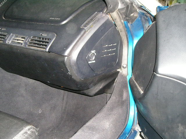
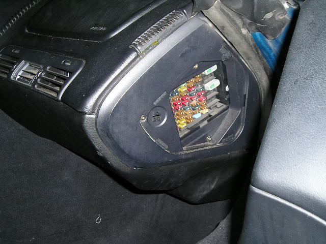
Long story short, on an error code 33, check the Instrument panel fuse first.
typical symtoms
car starts and does not idle consistently (so you might think TPS (set at .54 volts)
or the IAC is gummed up, (clean and test if required) look for vacuum leaks.
it also helps to throw a can or two of fuel injector cleaner in the fuel tank and get out the multi meter and verify the OHMS resistance in the ignition wires,
and changing to new spark plugs won,t hurt either,
changing the fuel filter can,t hurt.
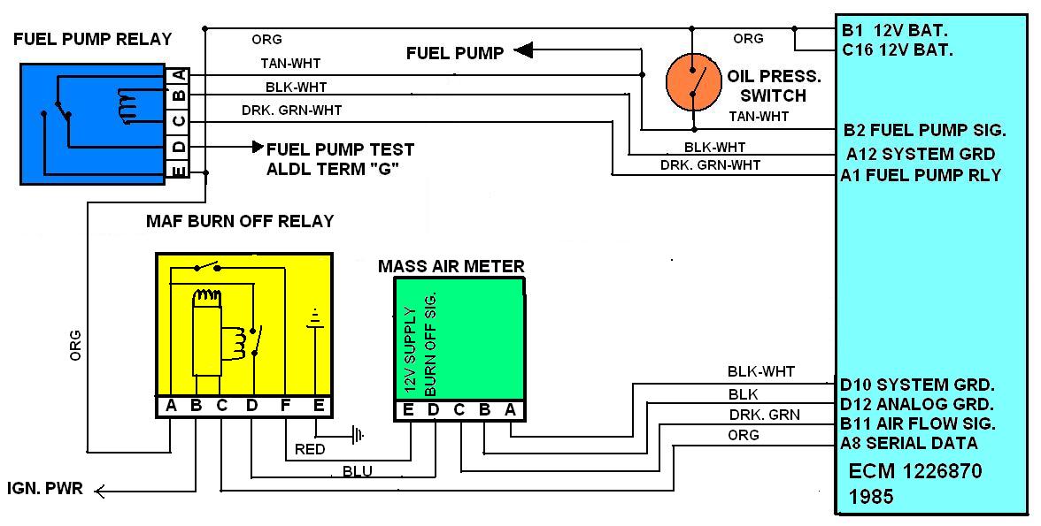
http://garage.grumpysperformance.com/index.php?threads/maf-burn-off-relay-info.661/#post-908
http://garage.grumpysperformance.com/index.php?threads/testing-1985-89-m-a-f-sensor.1475/#post-3325
http://garage.grumpysperformance.com/index.php?threads/adjusting-your-tps-and-iac.168/#post-82331
http://garage.grumpysperformance.com/index.php?threads/c4-c5-corvette-trouble-codes.2697/#post-70653
http://garage.grumpysperformance.co...vette-fuel-pump-replacement.15269/#post-88619
http://garage.grumpysperformance.co...-won-t-start-intermittently.14212/#post-72158
http://garage.grumpysperformance.co...asic-trouble-shooting-on-the-c4.302/#post-367
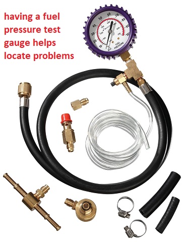
http://garage.grumpysperformance.com/index.php?threads/tpi-fuel-pressure-issue.10385/#post-42943
http://garage.grumpysperformance.co...-runs-rough-idles-and-sometimes-stalls.10688/
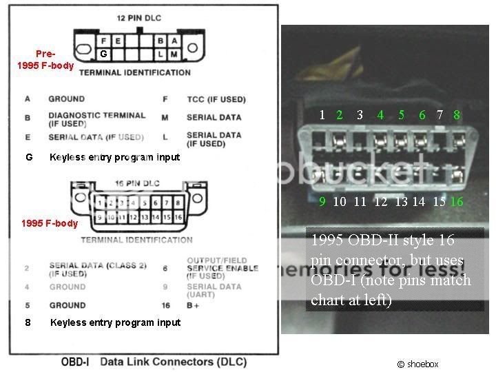
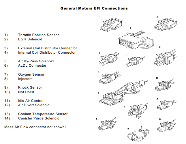
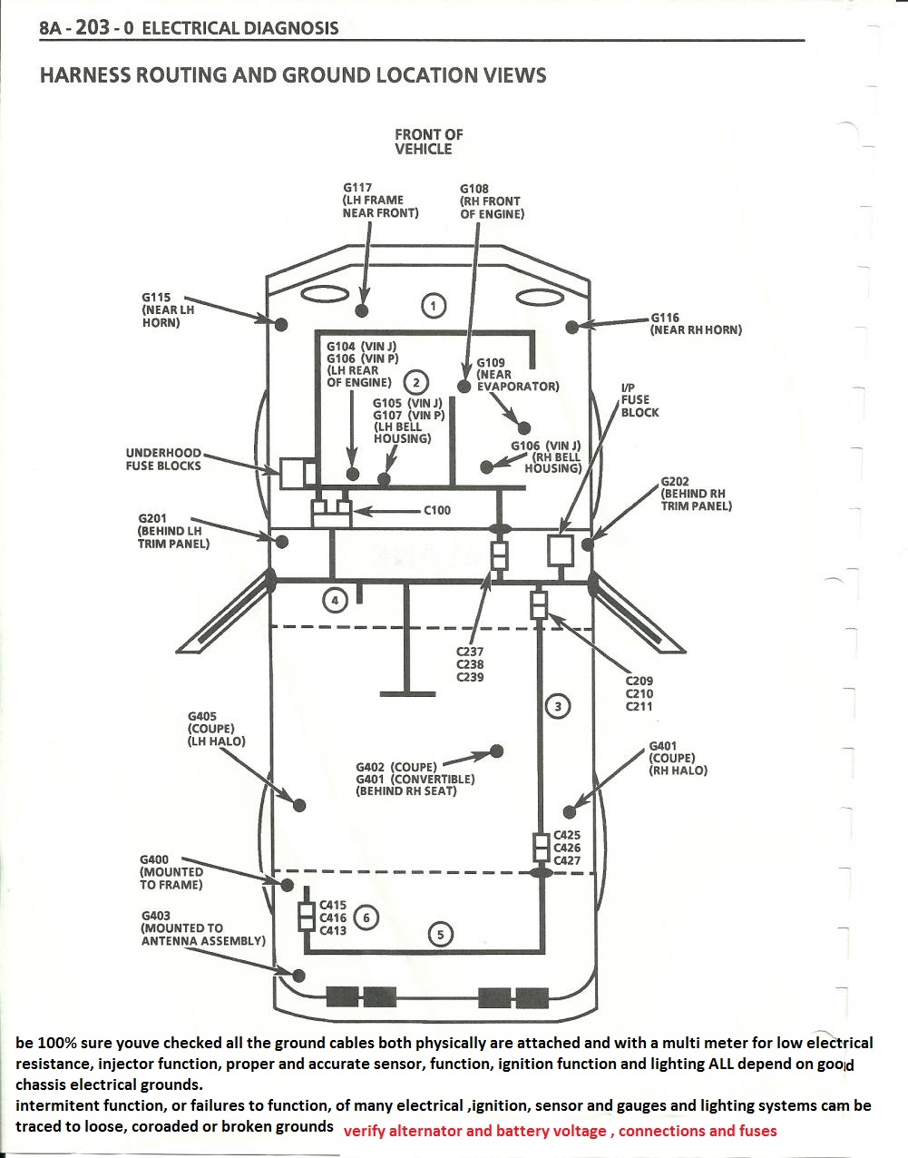
be aware the electrical grounds 104-105,106,107 must be checked and firmly connected to the engine
here i copied this :Just some additional info for the codes for the 85-91 tpi OBDI .
http://www.corvettedoctor.com/1985_91_DTC_Codes.html
http://garage.grumpysperformance.co...rouble-shooting-flow-chart-info.596/#post-793

Code #12: Normal No Codes.
Code #13: Open Oxygen Sensor Circuit.
Code #14: Coolant Sensor Circuit Low.
Code #15: Coolant Sensor Circuit High.
Code #21: Throttle Position Sensor High.
Code #22: Throttle Position Sensor Low.
Code #23: Manifold Air Temperature Circuit High.
Code #24: Vehicle Speed Sensor.
Code #25: Manifold Air Temperature Circuit Low.
Code #32: EGR System Failure.
Code #33: Mass Air Flow Sensor High.
Code #34: Mass Air Flow Sensor Low.
Code #36: Mas Air Flow Sensor Burn-Off Function Fault.
Code #41: Cylinder Select Error.
Code #42: Electronic Spark Timing.
Code #43: Electronic Spark Control.
Code #44: Lean Exhaust indication.
Code #45: Rich Exhaust Indication.
Code #46: Vehicle Anti Theft Fault.
Code #51: Faulty Mem-Cal.
Code #52: Fuel Calpak Missing.
Code #52: (1990-91 Corvette Only): Engine Oil Temperature Sensor Low.
Code #53: System Over Voltage.
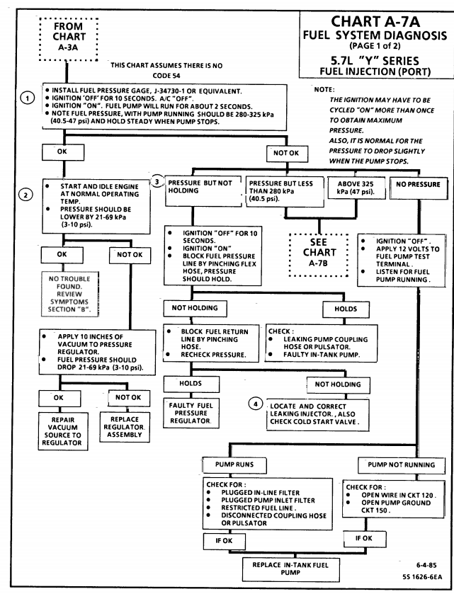
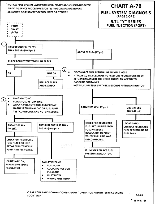
Code #54: Fuel Pump Circuit Low Voltage.
Code #55: Defective ECM.
Code #62: Engine Oil Temperature Sensor Circuit High.
CODE 33
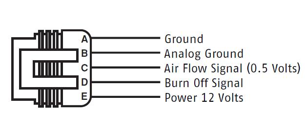
Trouble Code 33 indicates that the Mass Air Flow (MAF) sensor is reporting more air is entering the engine than makes sense based on RPM and TPS. The MAF sensor produces a frequency output; around 30 Hz at idle to 150 Hz under acceleration. The frequency varies proportionally to airflow. The ECM monitors the frequency and thus determines airflow into the engine. Typical idle MAF is 5 to 7 grams per second.
The conditions for setting this code are:
no Code 21 or 22 (TPS Error) present, and
the air flow reported is > 40 grams per second, and
TPS indicates < 10% throttle position, and
the engine speed is 1400 RPM or less, and
the above conditions exist for over 5 seconds.
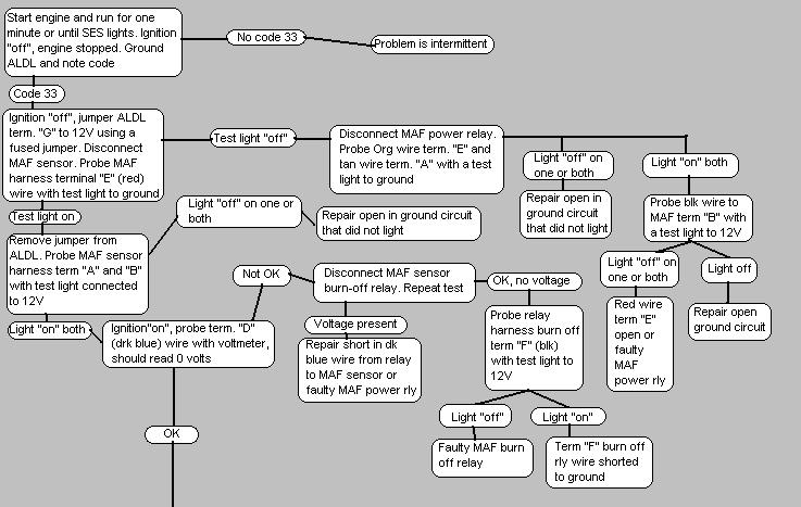
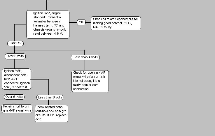
Typical causes for this code include:
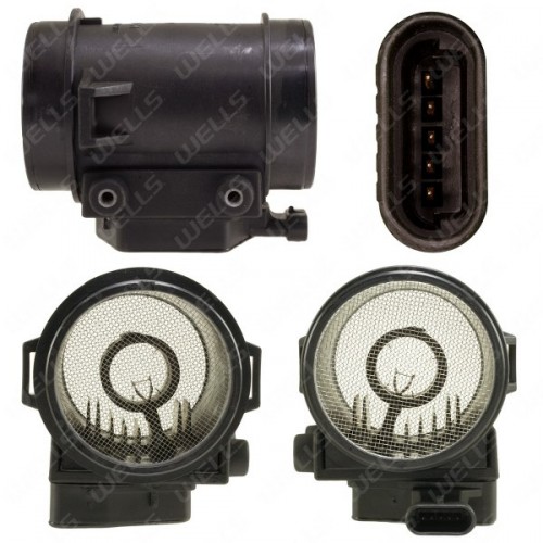
1) Faulty MAF-to-ECM connection
2) Exceedingly noisy spark plug wires
3) Poor routing of MAF harness (i.e. near coil packs)
4) Maladjusted TPS sensor
5) Defective MAF sensor
6) Defective ECM
Re: MAF & code 34
the threads linked below may help, but its more than likely a bad temp sensor or the TPS OR IAC is out of adjustment. so the first thing Id suggest is to adjust the TPS and IAC per the linked info and check for loose connections and vacuum leaks, and loose plenum and intake runner gaskets
34 Mass Air Flow Circuit (1985-1990) Clean the throttle body. Check MAF connections. Replace MAF relay. Replace MAF Sensor. Possible ECM failure.
34 Manifold Absolute Pressure Low (1984) Check Vacuum hoses associated with MAP sensor. Check wiring and connections, particularly at ECM. Replace the sensor. Possible ECM failure.
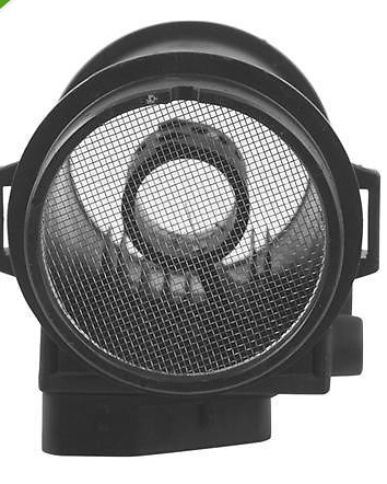
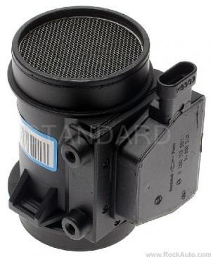
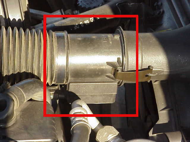
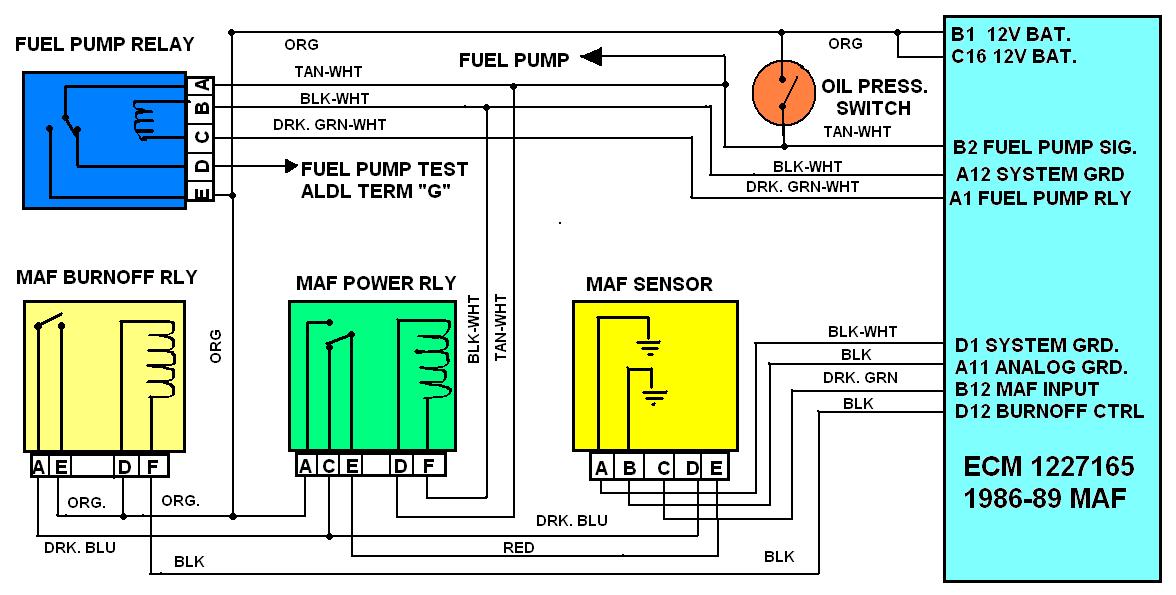
MAF SENSORS AND RELAYS ARE FREQUENT SOURCE OF INTERMEDIATE OR HARD TO ISOLATE RUN ISSUES ON EARLIER TPI CORVETTES SO CHECK THEIR FUNCTION
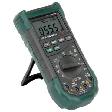
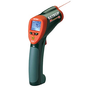
a factory shop manual and a v.o.m. meter come in handy for testing!
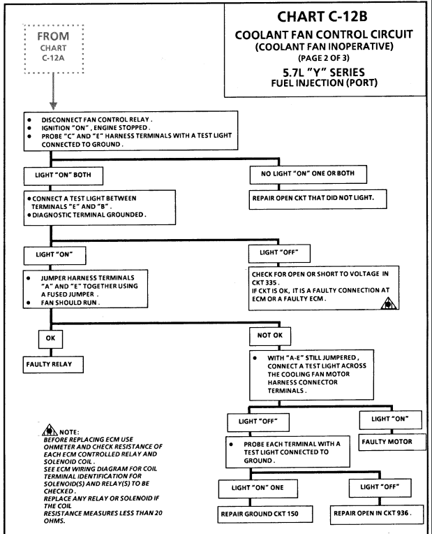
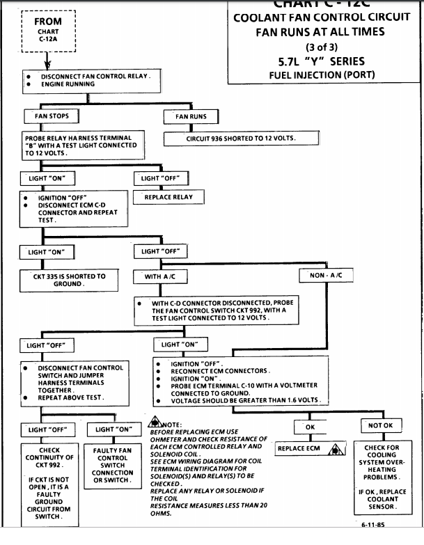
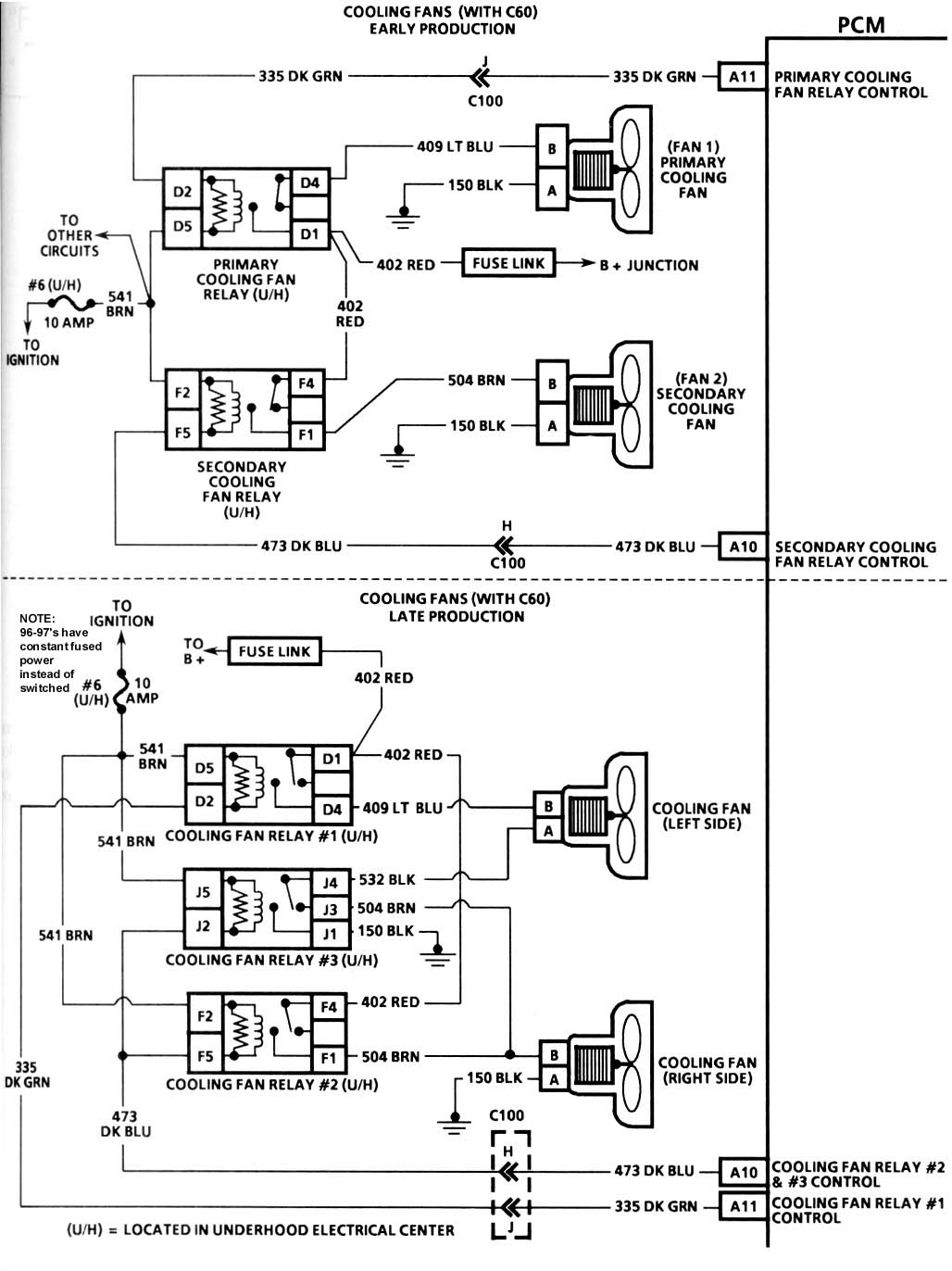
http://www.chevythunder.com/Flow chart index.htm
http://www.mamotorworks.com/corvette-c4 ... 6-893.html
https://www.zip-corvette.com/85-89-high-performance-adjustable-maf-sensor.html
85-89 High Performance Adjustable MAF Sensor
https://www.rockauto.com/en/catalog...,exhaust+&+emission,mass+air+flow+sensor,5128
--------------------------------------------------------------------------------
CODE 34
Trouble Code 34 indicates that the Mass Air Flow (MAF) sensor is reporting less air is entering the engine than makes sense based on RPM and TPS. The MAF sensor produces a frequency output; around 30 Hz at idle to 150 Hz under acceleration. The frequency varies proportionally to airflow. The ECM monitors the frequency and thus determines airflow into the engine. Typical idle MAF is 5 to 7 grams per second.
The conditions for setting this code are:
no Code 21 or 22 (TPS Error) present, and
the air flow reported is < 4 grams per second, and
TPS indicates 10% or more throttle position, and
the engine speed is 1800 RPM or higher, and
the above conditions exist for over 5 seconds.
Typical causes for this code include:
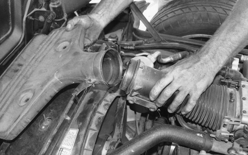
1) Faulty air ducting to or from MAF sensor
2) Faulty ECM-to-MAF connections
3) Poor routing of MAF harness (i.e. near coil packs)
4) Maladjusted TPS sensor
5) Defective MAF sensor
6) Defective ECM

 1989 corvette shows a trouble code #33
related info links
http://garage.grumpysperformance.co...your-c4-corvette-runs-badly.15212/#post-87228
http://garage.grumpysperformance.com/index.php?threads/adjusting-your-tps-and-iac.168/#post-82331
http://garage.grumpysperformance.co...lay-switch-locations-and-info.728/#post-72181
http://garage.grumpysperformance.co...le-shooting-flow-chart-info.11536/#post-71845
http://garage.grumpysperformance.com/index.php?threads/c4-c5-corvette-trouble-codes.2697/#post-70653
http://garage.grumpysperformance.co...s-air-flow-vs-speed-density.11952/#post-56852
http://garage.grumpysperformance.co...urrent-flow-grounds-and-more.3504/#post-54624
http://garage.grumpysperformance.com/index.php?threads/diagnoseing-tpi-lt1-problems.1241/#post-3037
http://garage.grumpysperformance.co...g-tpi-crossfire-or-lt1-vette.1401/#post-27000
http://garage.grumpysperformance.co...-idles-and-sometimes-stalls.10688/#post-46303
http://garage.grumpysperformance.com/index.php?threads/testing-1985-89-m-a-f-sensor.1475/#post-43635
typical symtoms
car starts and does not idle consistently (so you might think TPS (set at .54 volts)
or the IAC is gummed up, (clean and test if required) look for vacuum leaks.
it also helps to throw a can or two of fuel injector cleaner in the fuel tank and get out the multi meter and verify the OHMS resistance in the ignition wires,
and changing to new spark plugs won,t hurt either,
changing the fuel filter can,t hurt.
http://garage.grumpysperformance.com/index.php?threads/maf-burn-off-relay-info.661/#post-908
http://garage.grumpysperformance.com/index.php?threads/testing-1985-89-m-a-f-sensor.1475/#post-3325
http://garage.grumpysperformance.com/index.php?threads/adjusting-your-tps-and-iac.168/#post-82331
http://garage.grumpysperformance.com/index.php?threads/c4-c5-corvette-trouble-codes.2697/#post-70653
http://garage.grumpysperformance.co...vette-fuel-pump-replacement.15269/#post-88619
http://garage.grumpysperformance.co...-won-t-start-intermittently.14212/#post-72158
http://garage.grumpysperformance.co...asic-trouble-shooting-on-the-c4.302/#post-367
http://garage.grumpysperformance.com/index.php?threads/tpi-fuel-pressure-issue.10385/#post-42943
http://garage.grumpysperformance.co...-runs-rough-idles-and-sometimes-stalls.10688/
be aware the electrical grounds 104-105,106,107 must be checked and firmly connected to the engine
here i copied this :Just some additional info for the codes for the 85-91 tpi OBDI .
http://www.corvettedoctor.com/1985_91_DTC_Codes.html
http://garage.grumpysperformance.co...rouble-shooting-flow-chart-info.596/#post-793
Code #12: Normal No Codes.
Code #13: Open Oxygen Sensor Circuit.
Code #14: Coolant Sensor Circuit Low.
Code #15: Coolant Sensor Circuit High.
Code #21: Throttle Position Sensor High.
Code #22: Throttle Position Sensor Low.
Code #23: Manifold Air Temperature Circuit High.
Code #24: Vehicle Speed Sensor.
Code #25: Manifold Air Temperature Circuit Low.
Code #32: EGR System Failure.
Code #33: Mass Air Flow Sensor High.
Code #34: Mass Air Flow Sensor Low.
Code #36: Mas Air Flow Sensor Burn-Off Function Fault.
Code #41: Cylinder Select Error.
Code #42: Electronic Spark Timing.
Code #43: Electronic Spark Control.
Code #44: Lean Exhaust indication.
Code #45: Rich Exhaust Indication.
Code #46: Vehicle Anti Theft Fault.
Code #51: Faulty Mem-Cal.
Code #52: Fuel Calpak Missing.
Code #52: (1990-91 Corvette Only): Engine Oil Temperature Sensor Low.
Code #53: System Over Voltage.
Code #54: Fuel Pump Circuit Low Voltage.
Code #55: Defective ECM.
Code #62: Engine Oil Temperature Sensor Circuit High.
CODE 33
Trouble Code 33 indicates that the Mass Air Flow (MAF) sensor is reporting more air is entering the engine than makes sense based on RPM and TPS. The MAF sensor produces a frequency output; around 30 Hz at idle to 150 Hz under acceleration. The frequency varies proportionally to airflow. The ECM monitors the frequency and thus determines airflow into the engine. Typical idle MAF is 5 to 7 grams per second.
The conditions for setting this code are:
no Code 21 or 22 (TPS Error) present, and
the air flow reported is > 40 grams per second, and
TPS indicates < 10% throttle position, and
the engine speed is 1400 RPM or less, and
the above conditions exist for over 5 seconds.
Typical causes for this code include:
1) Faulty MAF-to-ECM connection
2) Exceedingly noisy spark plug wires
3) Poor routing of MAF harness (i.e. near coil packs)
4) Maladjusted TPS sensor
5) Defective MAF sensor
6) Defective ECM
Re: MAF & code 34
the threads linked below may help, but its more than likely a bad temp sensor or the TPS OR IAC is out of adjustment. so the first thing Id suggest is to adjust the TPS and IAC per the linked info and check for loose connections and vacuum leaks, and loose plenum and intake runner gaskets
34 Mass Air Flow Circuit (1985-1990) Clean the throttle body. Check MAF connections. Replace MAF relay. Replace MAF Sensor. Possible ECM failure.
34 Manifold Absolute Pressure Low (1984) Check Vacuum hoses associated with MAP sensor. Check wiring and connections, particularly at ECM. Replace the sensor. Possible ECM failure.
MAF SENSORS AND RELAYS ARE FREQUENT SOURCE OF INTERMEDIATE OR HARD TO ISOLATE RUN ISSUES ON EARLIER TPI CORVETTES SO CHECK THEIR FUNCTION
a factory shop manual and a v.o.m. meter come in handy for testing!
http://www.chevythunder.com/Flow chart index.htm
http://www.mamotorworks.com/corvette-c4 ... 6-893.html
https://www.zip-corvette.com/85-89-high-performance-adjustable-maf-sensor.html
85-89 High Performance Adjustable MAF Sensor
https://www.rockauto.com/en/catalog...,exhaust+&+emission,mass+air+flow+sensor,5128
--------------------------------------------------------------------------------
CODE 34
Trouble Code 34 indicates that the Mass Air Flow (MAF) sensor is reporting less air is entering the engine than makes sense based on RPM and TPS. The MAF sensor produces a frequency output; around 30 Hz at idle to 150 Hz under acceleration. The frequency varies proportionally to airflow. The ECM monitors the frequency and thus determines airflow into the engine. Typical idle MAF is 5 to 7 grams per second.
The conditions for setting this code are:
no Code 21 or 22 (TPS Error) present, and
the air flow reported is < 4 grams per second, and
TPS indicates 10% or more throttle position, and
the engine speed is 1800 RPM or higher, and
the above conditions exist for over 5 seconds.
Typical causes for this code include:
1) Faulty air ducting to or from MAF sensor
2) Faulty ECM-to-MAF connections
3) Poor routing of MAF harness (i.e. near coil packs)
4) Maladjusted TPS sensor
5) Defective MAF sensor
6) Defective ECM
1989 corvette shows a trouble code #33related info links
http://garage.grumpysperformance.co...your-c4-corvette-runs-badly.15212/#post-87228
http://garage.grumpysperformance.com/index.php?threads/adjusting-your-tps-and-iac.168/#post-82331
http://garage.grumpysperformance.co...lay-switch-locations-and-info.728/#post-72181
http://garage.grumpysperformance.co...le-shooting-flow-chart-info.11536/#post-71845
http://garage.grumpysperformance.com/index.php?threads/c4-c5-corvette-trouble-codes.2697/#post-70653
http://garage.grumpysperformance.co...s-air-flow-vs-speed-density.11952/#post-56852
http://garage.grumpysperformance.co...urrent-flow-grounds-and-more.3504/#post-54624
http://garage.grumpysperformance.com/index.php?threads/diagnoseing-tpi-lt1-problems.1241/#post-3037
http://garage.grumpysperformance.co...g-tpi-crossfire-or-lt1-vette.1401/#post-27000
http://garage.grumpysperformance.co...-idles-and-sometimes-stalls.10688/#post-46303
http://garage.grumpysperformance.com/index.php?threads/testing-1985-89-m-a-f-sensor.1475/#post-43635
Last edited: