grumpy I'm going crazy trying to figure this out!. my 1995 corvette cooling fans only coming on if air conditioner on & cooling, please help
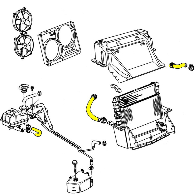
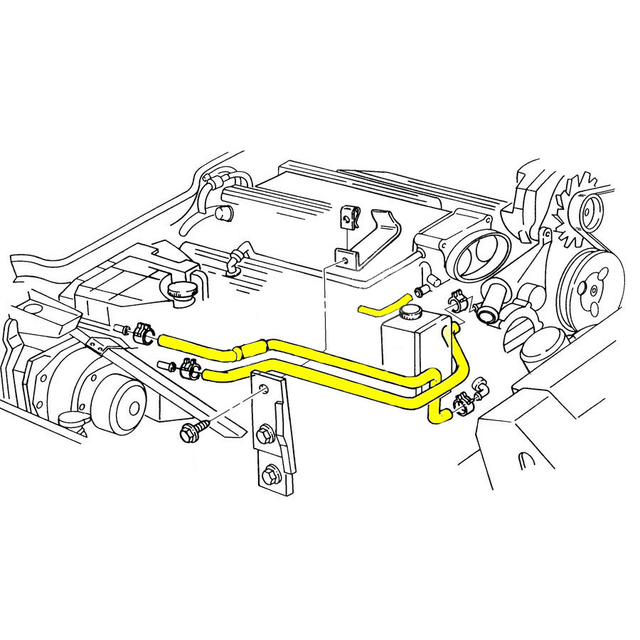
1995-96 corvette cooling hoses
1996 radiator cooling fan relay how to test
Hello all, I have a 1996 Vette LT-4, radiator cooling fans are not coming on. I have checked the fuse panel on the passenger side of the dash, I have also checked the maxi fuses in front on the battery. am now desirous of checking the cooling fan relays, how to do this? thanks in advance for any/all guidance
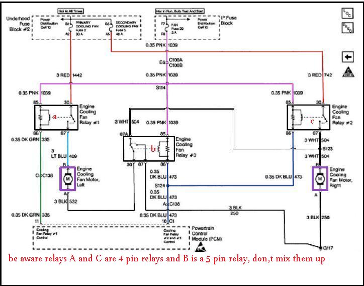
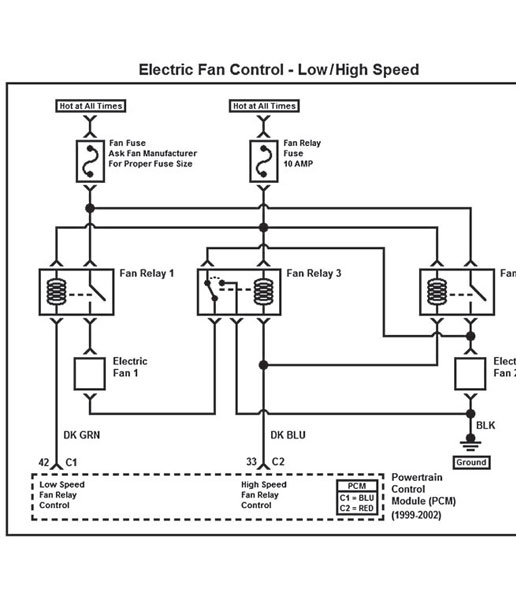
There are three relays involved.
You can identify the relays by the color of the wires at each relay socket.
Turn the ignition On.
At the relay socket.
Ground the Dark Green wire and both fans should run at low speed.
Ground both the Dark green wire and the Dark Blue wire and both fans should run at hi speed.
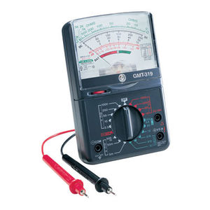
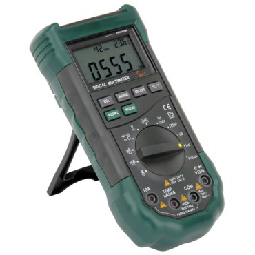
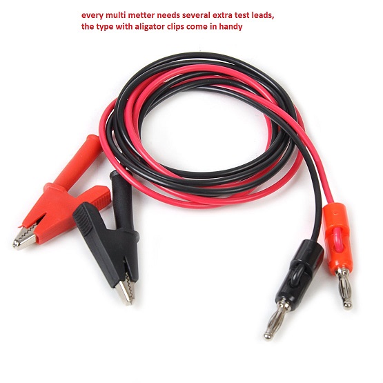
every mechanic needs an ANALOG multi meter for testing capacitors with a micro farad scale, AND a DIGITAL MULTI METER
http://forum.grumpysperformance.com/viewtopic.php?f=36&t=63&p=3403&hilit=vats#p3403
use of a shop manual and multi meter can be very helpful
http://www.harborfreight.com/5-in-1-digital-multimeter-98674.html
READ THIS THREAD
http://forum.grumpysperformance.com/viewtopic.php?f=32&t=3954
READ THESE LINKS AND SUB LINKS
http://garage.grumpysperformance.com/index.php?threads/cooling-off-that-c4-corvette.3954/
http://garage.grumpysperformance.co...-air-conditioner-on-cooling.12232/#post-59597
http://garage.grumpysperformance.co...sion-and-oil-cooler-increases-durability.176/
http://garage.grumpysperformance.co...ans-cooler-on-a-c4-corvette.10514/#post-44478
http://garage.grumpysperformance.com/index.php?threads/i-need-a-new-lt1-water-pump.10723/
a defective fan relay, or blown fuse are HIGH on the list of potential reasons for fan failure to come on reasons (THERES THREE , OS BUY THREE)
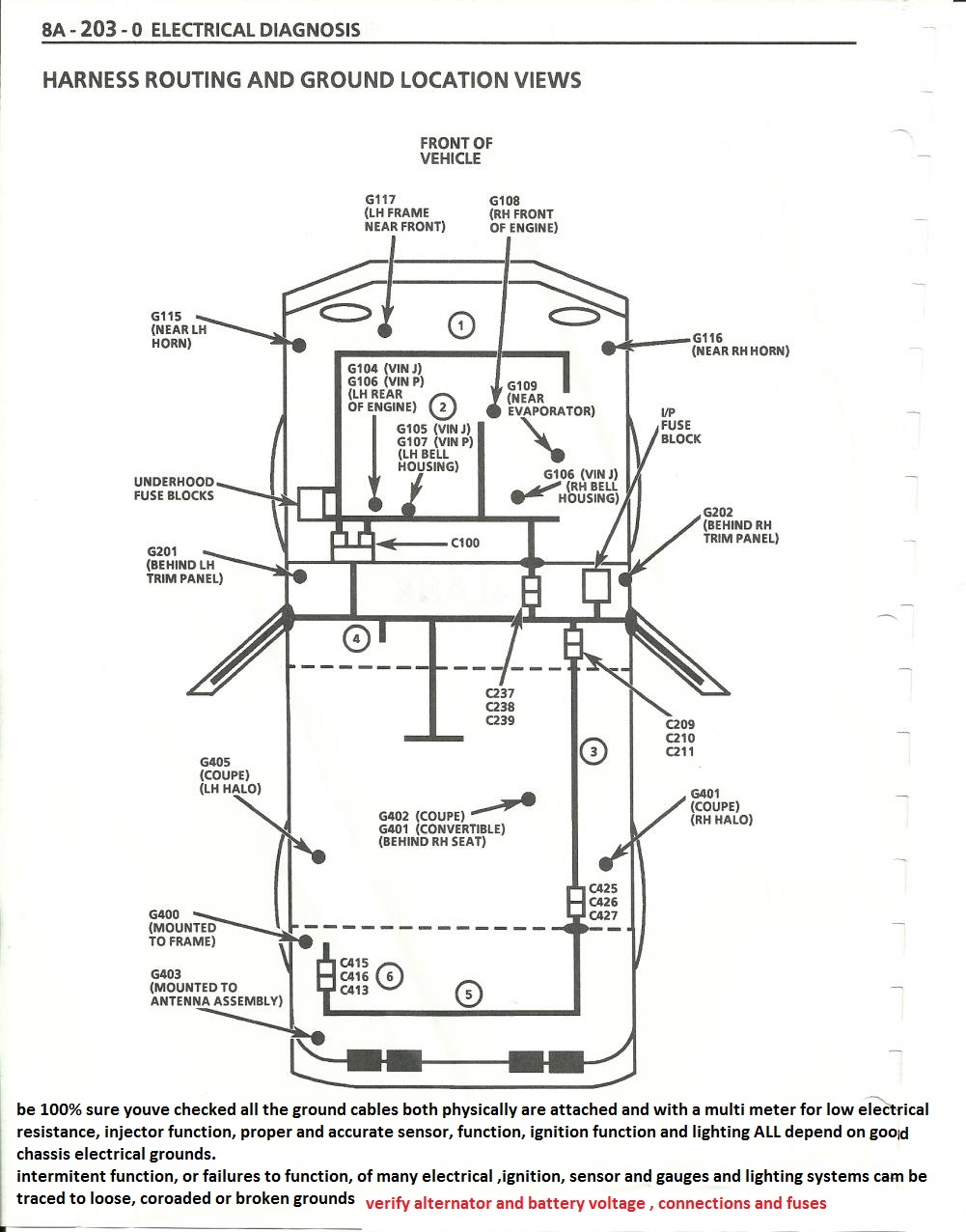
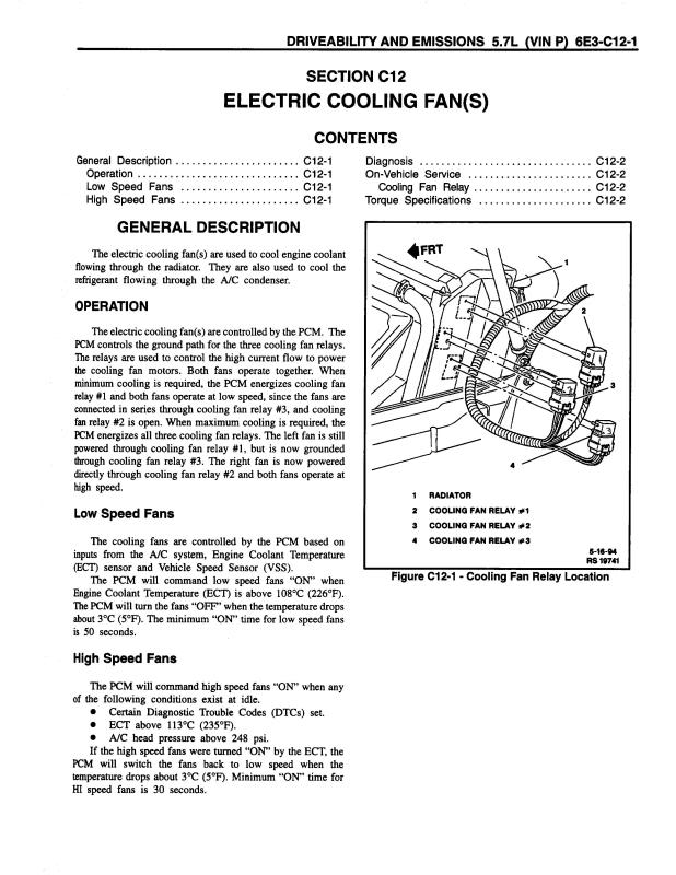
they are all located on the drivers side of the radiator shroud
Manually spin the fan blade of the fan that doesn't work to
verify the fan motor isn't seized.
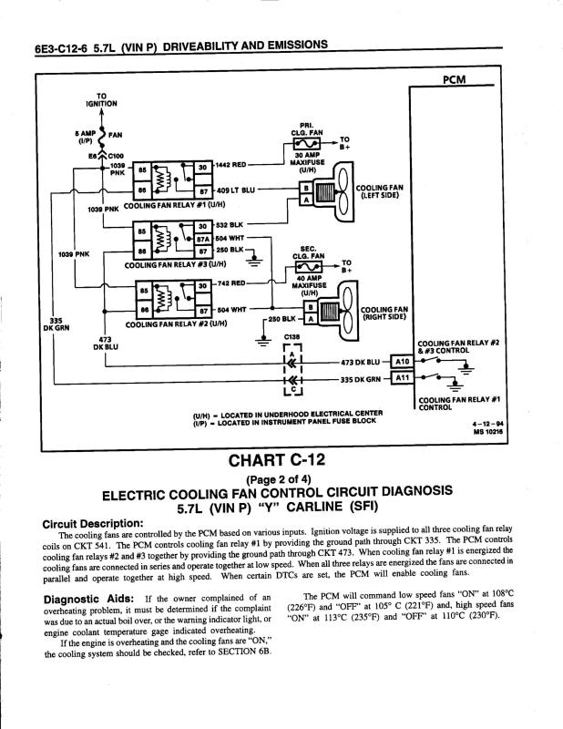
The fans use 3 relays mounted on the driver side
on the end of the radiator.
Primary cooling fan is an the driver side.
Secondary cooling fan is on the passenger side.
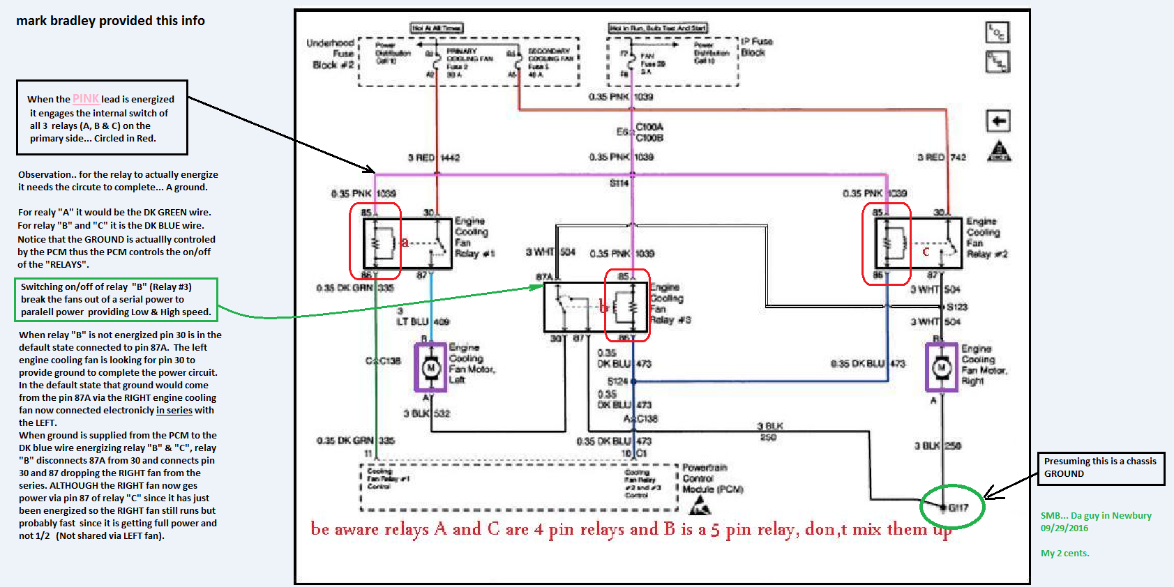
There are two modes of fan operation.
Both fans at half speed. 6 volts
Both fans at high speed. 12 volts.
There are two control lines the PCM grounds to
enable the fans.
PCM grounds the Dark Green wire for low speed.
Relay #1 is energized.
PCM grounds both the Dark Green wire and a Dark Blue
wire for high speed.
All three relays #1, #2 and #3 are energized.
Three fuses protect the circuits.
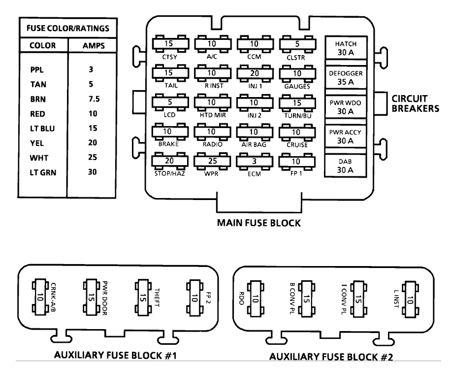
Fan fuse 5 amp located on passenger side of the dash.
This must be good because you say one fan does run.
Primary coolant fan 30 amp Maxifuse located under the hood.
Must be good if the driver side fan works.
Secondary coolant fan 40 amp Maxifuse located under the hood.
You can identify the relays by the color of the wires that
go to the relay sockets.
Relay #1 has the following colored wires.
Pink, Dark Green, Red and a Light blue wire.
Relay #2
Pink, Dark Blue, White and 2 Black wires.
Relay #3
Pink, Dark Blue, Red and a White wire.
To test the fans turn the ignition On.
Manually ground the control lines. Stick a nail
or probe, jumper wire etc... into the bottom of
the relay socket and ground the Dark Green wire.
Both fans should run at low speed.
Ground the Dark Green wire and the Dark Blue
wire and both fans should run at high speed.
Another method you can use is to carefully pry/remove
the plastic cover off of the relays. You can then
manually energize the relays by pushing down
on the metal plate.
Push down on the plate on #1 relay and both fans
should run at slow speed.
Push down the metal plate on all relays and both
fans should run at high speed.
Pro tip before starting - Label your relays Relay 1, Relay 2, and Relay 3 according to the wiring diagram (your first post) and what your physical relays represent. Even if its just a sticky note. Get it all straight and stick to the same annotation while you troubleshoot.
You'll need a multimeter than can measure DC voltage and continuity:
Remove all three relays so you're only dealing with the sockets
DC Voltage tests:
1. Confirm 12V between the socket for pin 85 and the negative battery terminal on all 3 relay sockets
2. Confirm 12v between the socket for pin 30 and the negative battery terminal on relay sockets 1 and 2
Continuity tests:
1. Confirm continuity with the end of the dark green wire and the socket for pin 86 for relay 1
2. Confirm continuity with the end of the dark blue wire and the socket for pin 86 for relay 2 AND relay 3.
3. Confirm continuity between the socket for pin 87 for relay 1 and side B of the left cooling fan connector
4. Confirm continuity between side A of the left cooling fan connector and side B of the right cooling fanconnector AND the socket for pin 87 for relay #2.
5. Confirm continuity between the socket for pin 87 for relay #3 and Negative Battery Terminal
6. Confirm continuity between side A of the right cooling connector and Negative Battery Terminal.
Do the steps in order and use the negative battery terminal for your connection when I specify to. Verifying at the negative battery terminal will ensure you're circuit is making a good connection to the chassis ground. If it doesn't make it all the way back to the battery, it's a crap ground and testing it my way will reveal the problem
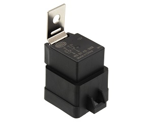
http://www.ebay.com/itm/1995-1996-C...Black-5-Pin-/381497615462?hash=item58d307a466
http://www.ecklerscorvette.com/corvette-engine-cooling-fan-relay-1995-1996.html
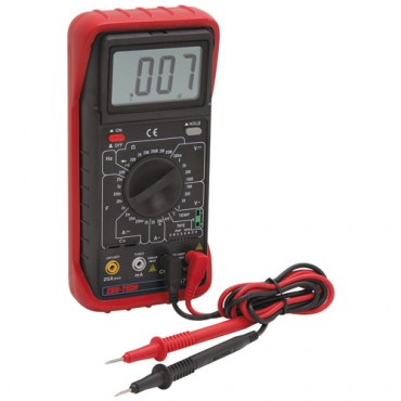
use of a shop manual and multi meter can be very helpful
http://www.harborfreight.com/5-in-1-digital-multimeter-98674.html
Here are some causes of overheating:
* Bad Thermostat or clogged t-stat
* Cooling system leaks/low coolant levels
* mixing two non-compatible anti-freeze types
* defective or the wrong water pump
* Leaky Head Gasket
* vacuum leaks in intake
* wrong fuel/air mix ratio
* incorrectly installed belts
* crud blocking the airflow thru radiator
* blocked or restricted air flow,missing duct work
* defective sensors or connections too sensors
* slime or sediment in radiator tubes
* one or both Fans Not Working correctly
* Leaky Water pump
* defective fan relays
* blown fuses
* over heated transmission coolant
* low alternator voltage
* low oil levels in engine
* incorrect ignition timing
* partly blocked catalytic converters
* Lower Radiator Hose Collapsing
* *Slipping Belt - Check belt tension and condition. A loose belt that slips may prevent the water pump from circulating coolant fast enough
Your engine may not be overheating at all. Your temperature gauge or warning lamp may be coming on because of a faulty coolant sensor. Sometimes this can be caused by a low coolant level or air trapped under the sensor.
http://www.ecklerscorvette.com/corvette-engine-cooling-fan-relay-1995-1996.html
Sensor
Location
Engine Coolant Temperature Sensor. Front of engine, below Throttle Body.
Engine Oil Temperature Sensor. Left rear of engine, just above the oil filter.
Oil Pressure Sender/Switch. Top, left hand rear of engine.
Fuel Quantity Sender. Top of fuel tank, beneath filler pipe escutcheon panel.
MAT (Manifold Absolute Temperature Sensor). Underside of manifold air plenum at rear.
Outside Temperature Sensor. Right side of engine, top right corner of radiator.
In Car Temp Temperature Sensor. Coupe: above left seat near interior courtesy light, Convertible: center of cargo compartment lid.
MAF (Mass Air Flow) Sensor. Front of engine ahead of throttle body.
Oxygen (O2) Sensor. Left side of engine, in exhaust pipe.
TPS (Throttle Position Sensor). Right side of throttle body at the front.
Sensor Outputs:
Sensor
Measured Value
Engine Coolant Temperature Sensor. 185 Ohms @ 210F, 3400 Ohms @ 68F, 7,500 Ohms @ 39 F.
Engine Oil Temperature Sensor. 185 Ohms @ 210 F, 3400 Ohms @ 68 F, 7,500 Ohms @39 F.
Oil Pressure Sender/Switch. 1 Ohms @ 0 PSI, 43 Ohms @ 30 PSI, 86 Ohms @ 60 PSI.
Fuel Quantity Sender. 0 Ohms @ Empty, 45 Ohms @ 1/2 Full, 90 Ohms @ Full.
MAT (Manifold Absolute Temperature Sensor). 185 Ohms @ 210 F, 3400 Ohms @ 70 F, 15,000 Ohms @ 40 F.
Outside Temperature Sensor. 4400 Ohms @ 60 F, 2200 Ohms @ 85 F.
In Car Temp Temperature Sensor. 4400 Ohms @ 60 F, 2200 Ohms @ 85 F.
MAF (Mass Air Flow) Sensor. .4 Volts @ idle, 5 Volts @ Full Throttle.
Oxygen (O2) Sensor. .1 Volt Lean Mixture, .9 Volt Rich Mixture.
TPS (Throttle Position Sensor). .54 Volts Idle, ~ 5 Volts Full Throttle.
its CRITICAL to keep the trans fluid clean and ideally changed about every 70K miles and use of a auxiliary cooler that keeps the fluid temp under about 170F is going to extend service life a good deal longer
http://garage.grumpysperformance.com/index.php?threads/c4-c5-corvette-trouble-codes.2697/#post-69239
RELATED THREADS CONTAINING INFO YOU'LL WANT
http://garage.grumpysperformance.co...e-out-intermittent-fan-issue.9229/#post-33215
http://garage.grumpysperformance.com/index.php?threads/cooling-off-that-c4-corvette.3954/
http://garage.grumpysperformance.co...ette-fan-motor-quit-working.10559/#post-45011
http://garage.grumpysperformance.co...lay-switch-locations-and-info.728/#post-54562
http://garage.grumpysperformance.com/index.php?threads/c4-c5-corvette-trouble-codes.2697/#post-51440
http://garage.grumpysperformance.co...sh-out-of-the-radiator-fins.11712/#post-54986
http://garage.grumpysperformance.com/index.php?threads/i-need-a-new-lt1-water-pump.10723/
http://garage.grumpysperformance.co...ans-cooler-on-a-c4-corvette.10514/#post-44478
http://garage.grumpysperformance.com/index.php?threads/electrical-problem.10714/#post-46692
Last edited: