Wanderwilly said:Help!! 1994 Vette with AC running. I understand both fans are supposed to run. Where do I start looking?
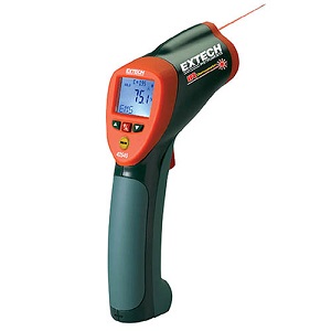
infrared thermometers are a very useful tool to track down issues with tuning, or mal functioning sensors , without verified facts your guessing.
this is the most consistently accurate I.R temp gun I've used for testing[/img]
http://www.testequipmentdepot.com/e...1100200223789&utm_content=All Extech Products
INFRARED TEMP GUN
Wide temperature range from -58 to 1832°F (-50 to 1000°C)
any time that your dealing with a potential temperature issue or a trouble issue where , knowing the exact temperature vs what a gauge might say, it helps to have a handy and accurate infrared temp gun handy to locate and confirm heat, levels.
http://www.harborfreight.com/5-in-1-dig ... 98674.html
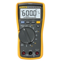
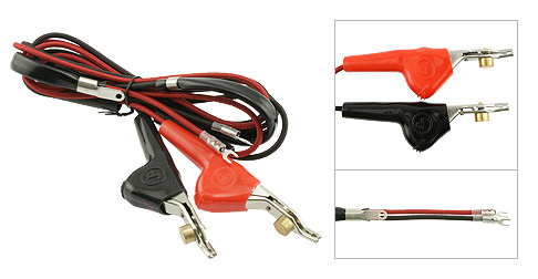
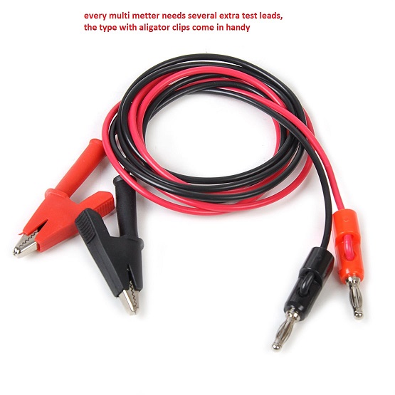
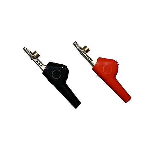
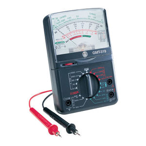
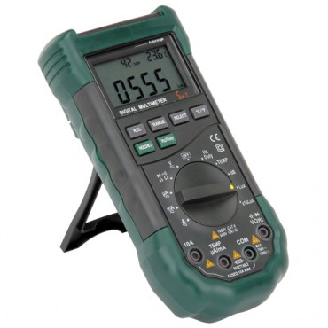
having a fluke multi meter, or at least a functioning multi meter, and an assortment of test leads helps
FLUKE is the brand of choice but they are expensive, shop around, Ive still got the original fluke multi meter I bought in HIGH SCHOOL and it STILL WORKS Ive purchase several imported multi meters from harbor freight , in the last 10 years alone and only one still works
http://www.fluke-direct.com/shop/itemDe ... urer=FLUKE
http://www.fluke-direct.com/shop/catego ... TERS&path=
this looks interesting with a discount coupon its discounted to about $169.99 until 4/30/18 plus $49.99 for a two year 100% warranty
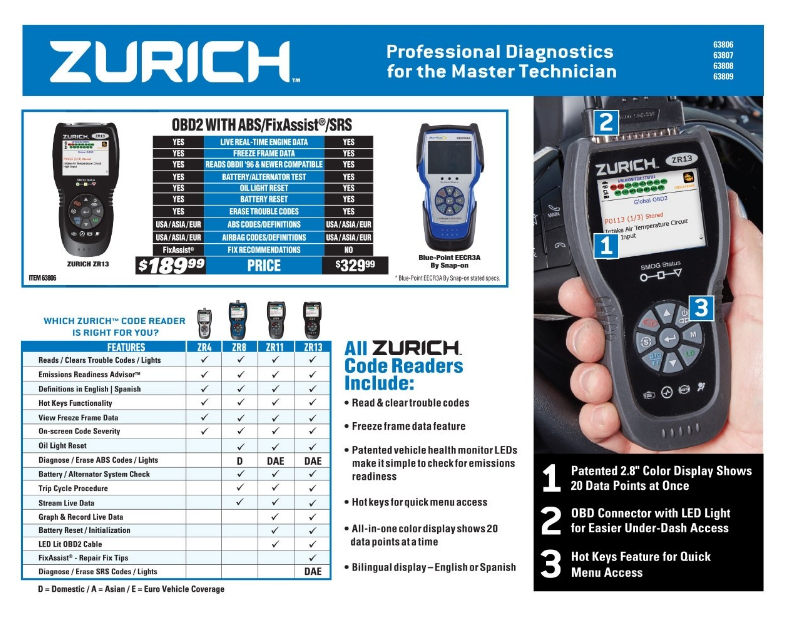
if you purchase a ZR13 auto code scanner, from HF,
you need this info
DOWN-LOAD AND PRINT IT OUT!
https://manuals.harborfreight.com/manuals/63000-63999/Q63806.pdf
https://manuals.harborfreight.com/manuals/63000-63999/63806.pdf
http://garage.grumpysperformance.co...996-corvettes-got-me-scratching-my-head.7499/

https://www.harborfreight.com/catalogsearch/result/index/?dir=asc&order=EAScore,f,EAFeatured+Weight,f,Sale+Rank,f&q=zr13

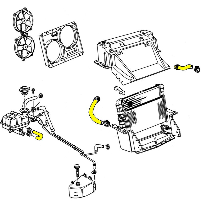
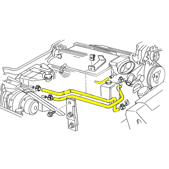
1995-96 corvette cooling hoses
(1) pull trouble codes
http://forum.grumpysperformance.com/viewtopic.php?f=32&t=2697
(2) GET A SHOP MANUAL FOR YOUR YEAR VETTE, and a multi meter
swap plugs on the fans to see if the other fan runs when its swapped with the known working electrical wire plug in fan connections, if it won,t its the fan itself,as both fans use the same connections
ROCK AUTO SELLS REPLACEMENT FAN MOTORS
ACDELCO Part # 158404 {#22104439} GM Original Equipment
$63.79
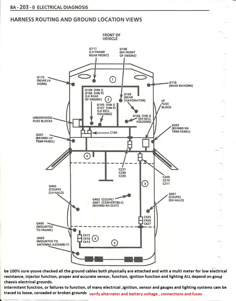
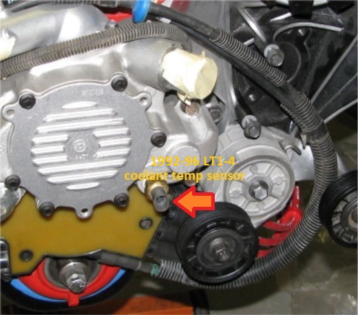
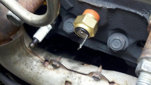
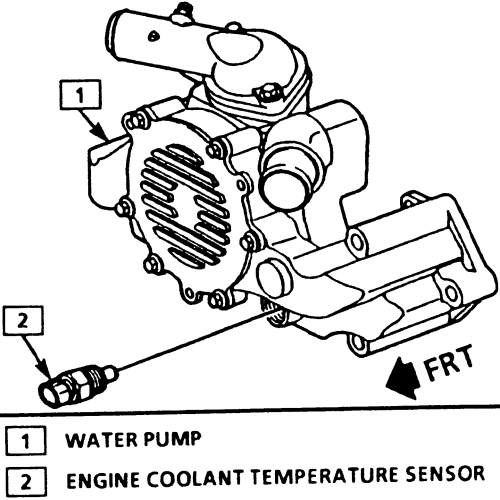
the coolant temp sensor for the PCM is on the water pump a black and a yellow wire.
every mechanic needs an ANALOG multi meter for testing capacitors with a micro farad scale, AND a DIGITAL MULTI METER
http://forum.grumpysperformance.com/viewtopic.php?f=36&t=63&p=3403&hilit=vats#p3403
use of a shop manual and multi meter can be very helpful
http://www.harborfreight.com/5-in-1-digital-multimeter-98674.html
READ THIS THREAD
http://forum.grumpysperformance.com/viewtopic.php?f=32&t=3954
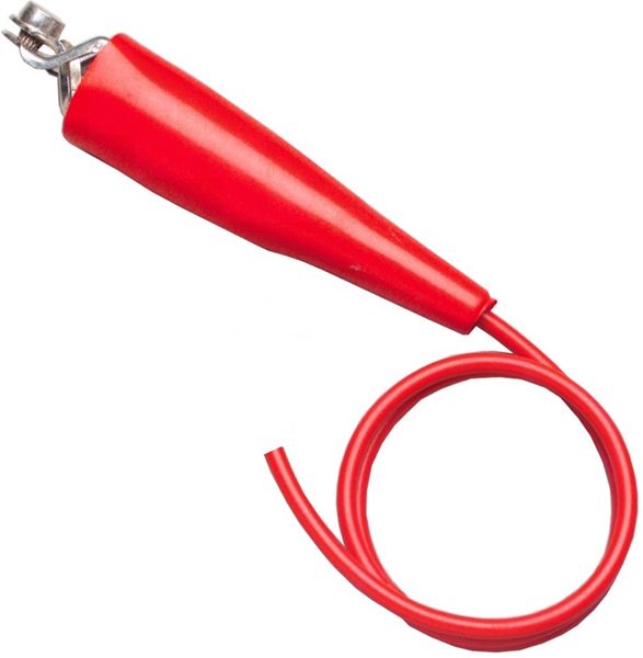
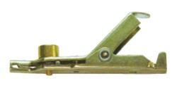
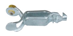
1984-1995 corvettes can have the fan tested buy using a paper clip between ports (A) and (B) and turning the ignition key two clicks (not starting the engine)
http://garage.grumpysperformance.com/index.php?threads/c4-c5-corvette-trouble-codes.2697/#post-18904
To recover ECM codes from the 1984 through 1993 Corvette, place a short as shown below between pins "A" and "B" on the ALDL (Assembly Line Diagnostic Link) connector. This connector is located under the dash just to the right of the steering column and has space for 12 pins although not all of the cavities will be populated.
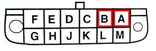
.
Turn the ignition switch to "On" but do not start the engine.
Depending on the model year, either the "Check Engine Light" or the "Service Engine Soon" will begin to flash.
As the code display sequence begins, you will see a flash followed by a pause and then two flashes. This is the indication for the number "12". The number 12 is a delimiter intended to show where the ECM code display starts and stops.
Code 12 will flash three times and then any stored codes will flash. When all codes have been displayed or if there are no stored codes, the number 12 will again flash three times.
For example, a problem with the EGR system (code 32) will be shown as 12, 12, 12, 32, 32, 32, 12, 12, 12.
This would be displayed on the Check Engine/Service Engine Soon light like this:
12: flash (pause), flash, flash, (long pause)
12: flash (pause), flash, flash, (long pause)
12: flash (pause), flash, flash, (long pause)
32: flash, flash, flash (pause) flash, flash (long pause)
32: flash, flash, flash (pause), flash, flash (long pause)
32: flash, flash, flash (pause), flash, flash (long pause)
12: flash (pause), flash, flash, (long pause)
12: flash (pause), flash, flash, (long pause)
12: flash (pause), flash, flash (long pause)
The ECM code display will repeat until you turn off the ignition switch and remove the short.
http://garage.grumpysperformance.com/index.php?threads/c4-c5-corvette-trouble-codes.2697/#post-18904
Manually spin the fan blade of the fan that doesn't work to
verify the fanmotor isn't seized.
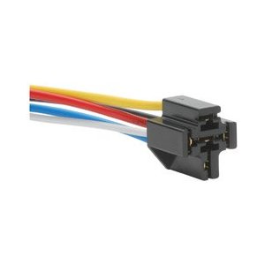
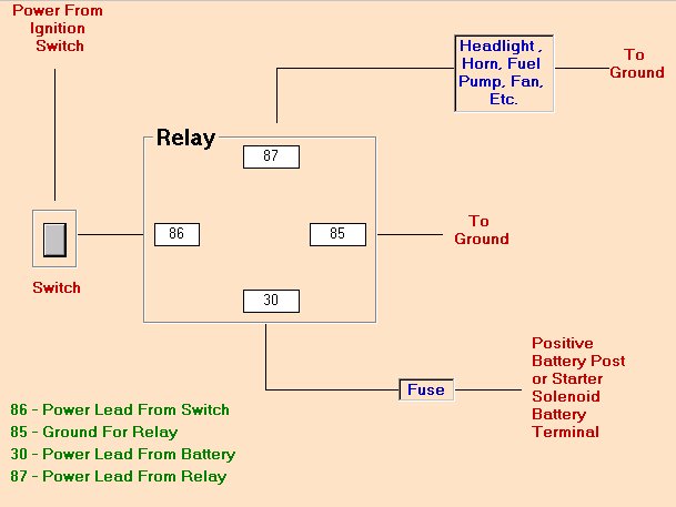
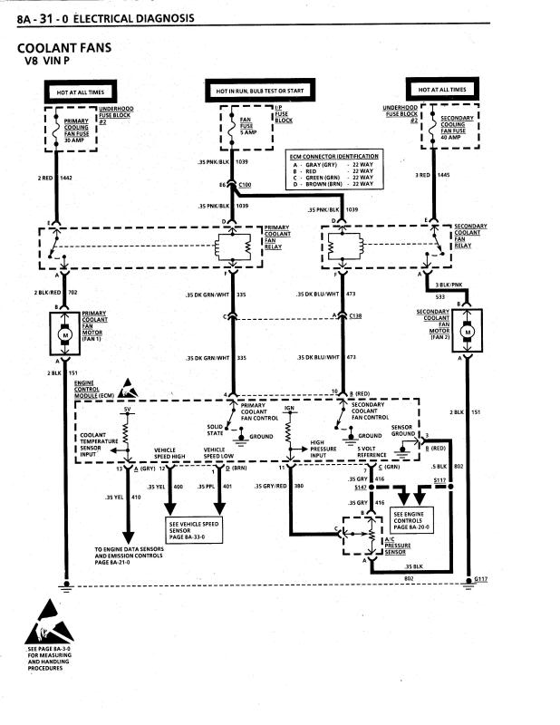
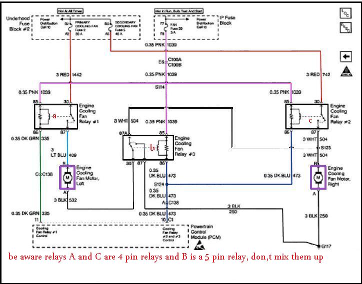
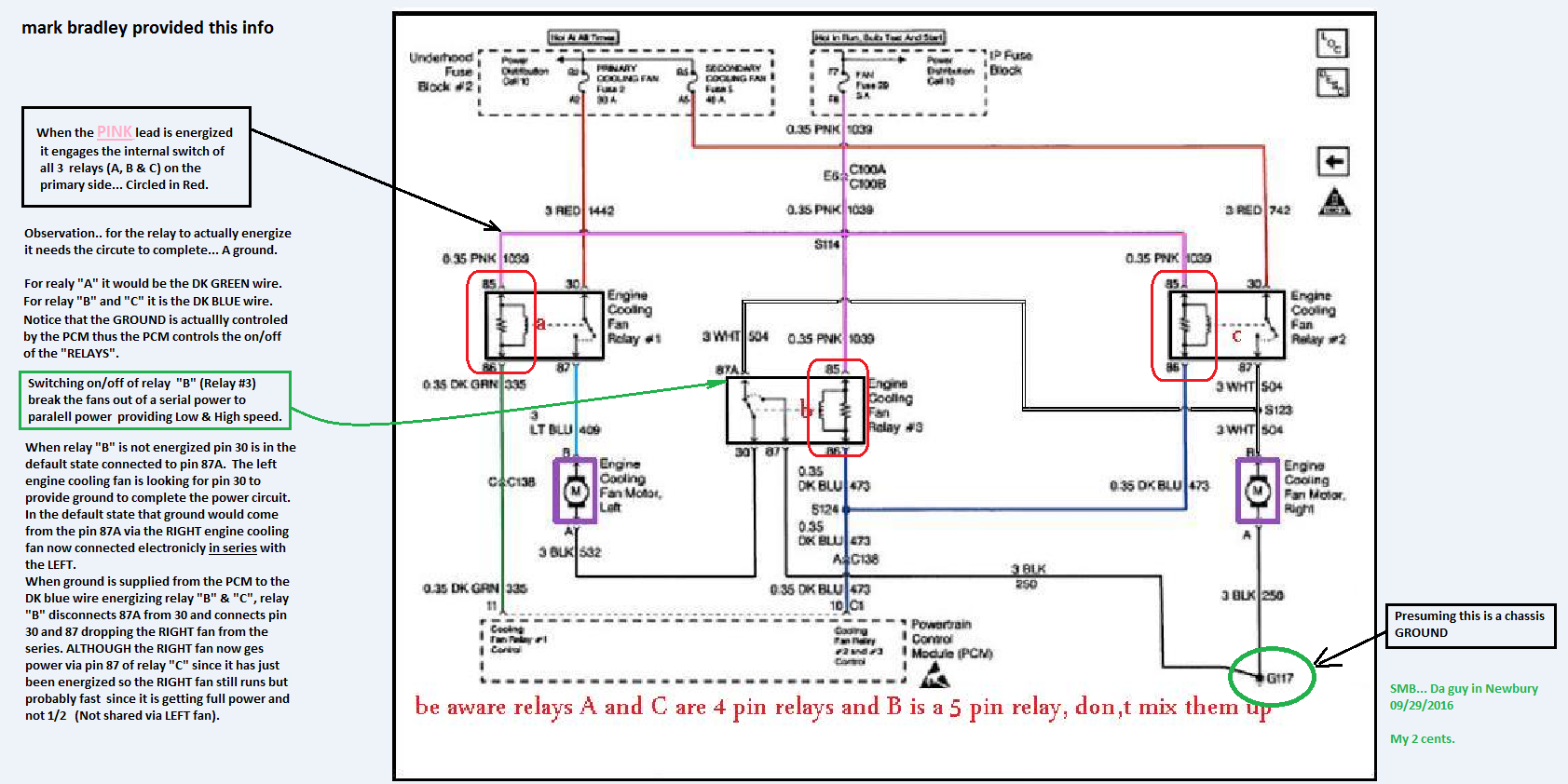
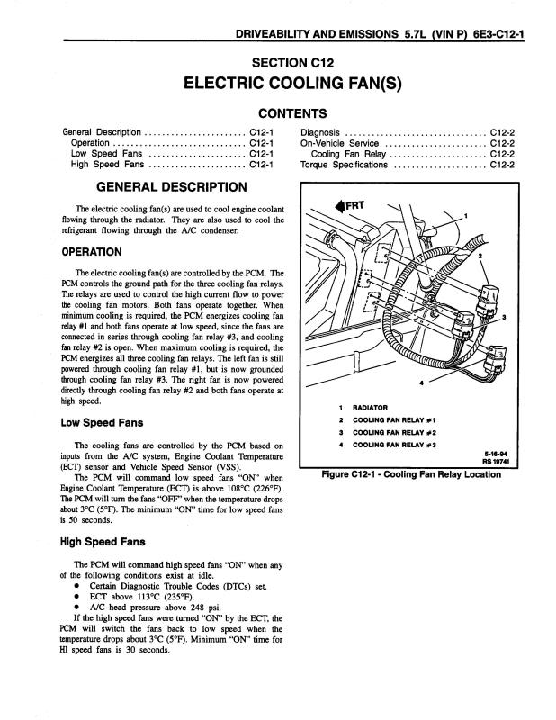
The fans use 3 relays mounted on the driver side
on the end of the radiator.
Primary cooling fan is an the driver side.
Secondary cooling fan is on the passenger side.
There are two modes of fan operation.
Both fans at half speed. 6 volts
Both fans at high speed. 12 volts.
There are two control lines the PCM grounds to
enable the fans.
PCM grounds the Dark Green wire for low speed.
Relay #1 is energized.
PCM grounds both the Dark Green wire and a Dark Blue
wire for high speed.
All three relays #1, #2 and #3 are energized.
Three fuses protect the circuits.
Fanfuse 5 amp located on passenger side of the dash.
This must be good because you say one fan does run.
Primary coolantfan 30 amp Maxifuse located under the hood.
Must be good if the driver side fan works.
Secondary coolantfan 40 amp Maxifuse located under the hood.
You can identify the relays by the color of the wires that
go to the relay sockets.
Relay #1 has the following colored wires.
Pink, Dark Green, Red and a Light blue wire.
Relay #2
Pink, Dark Blue, White and 2 Black wires.
Relay #3
Pink, Dark Blue, Red and a White wire.
To test the fans turn the ignition On.
Manually ground the control lines. Stick a nail
or probe, jumper wire etc... into the bottom of
the relay socket and ground the Dark Green wire.
Both fans should run at low speed.
Ground the Dark Green wire and the Dark Blue
wire and both fans should run at high speed.
Another method you can use is to carefully pry/remove
the plastic cover off of the relays. You can then
manually energize the relays by pushing down
on the metal plate.
Push down on the plate on #1 relay and both fans
should run at slow speed.
Push down the metalplate on all relays and both
fans should run at high speed.
The relays are all the same so you can swap them around.
these charts are for the 1985-89 vette cooling fans
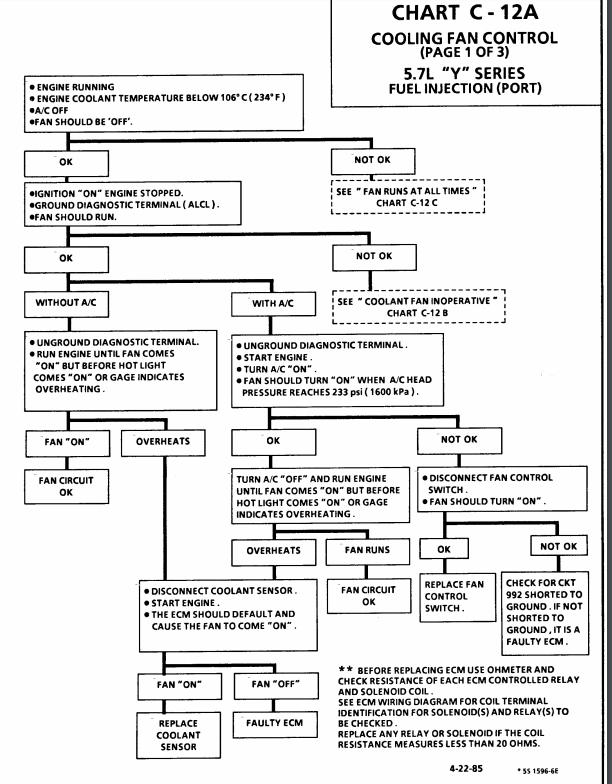
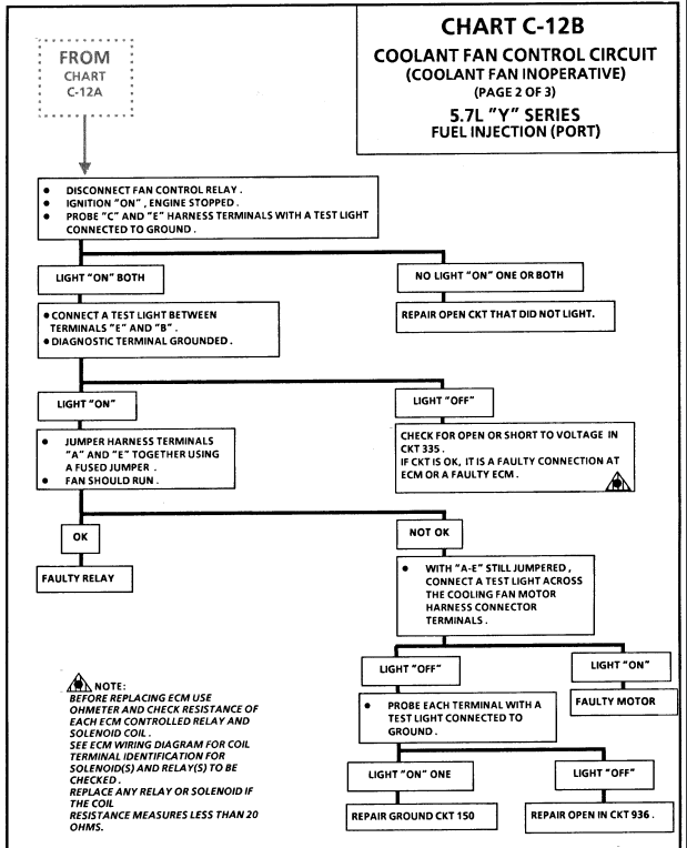

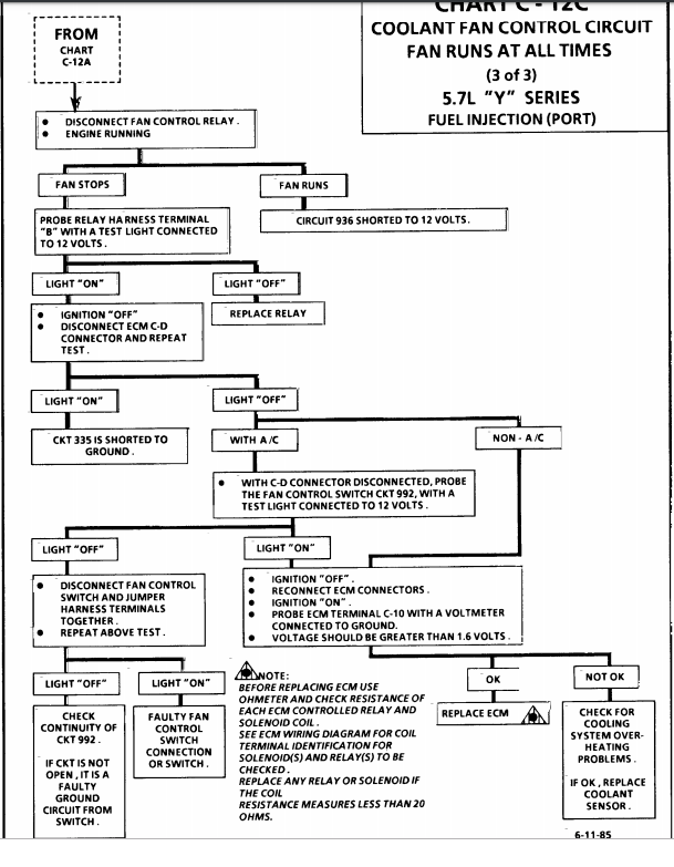
READ THESE LINKS AND SUB LINKS
http://garage.grumpysperformance.com/index.php?threads/cooling-off-that-c4-corvette.3954/
http://garage.grumpysperformance.co...-air-conditioner-on-cooling.12232/#post-59597
http://garage.grumpysperformance.co...sion-and-oil-cooler-increases-durability.176/
http://garage.grumpysperformance.com/index.php?threads/head-scratcher-cooling-issue.3010/#post-84329
http://garage.grumpysperformance.co...ans-cooler-on-a-c4-corvette.10514/#post-44478
http://garage.grumpysperformance.com/index.php?threads/i-need-a-new-lt1-water-pump.10723/
Last edited by a moderator: