240 Deg Timed Tri Y Headers

a few factors you might be over looking,
that have a pronounced effect on selecting header length

(1) the displacement of each individual cylinder

(2) the average rpm in which the engine operates

(3) the available room in the engine compartment and under the car available for the header too occupy

(4) the cost vs benefits the longer header design might provide, in the intended application

(5) the intended rpm range and power band or expected torque curve.

(6) the available fuel octane and the average monthly cost of fuel to the owners

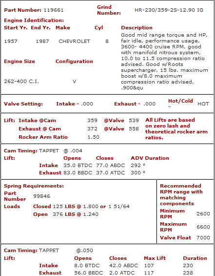
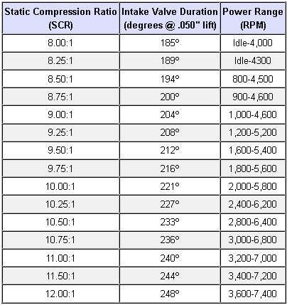
(7) obviously cam timing, lift and duration, must match the intended rpm range,
the cylinder head flow rates and the headers are designed for

most cars are sold for a blend of reasonably lower cost transportation, performance and longer term durability and increased passenger comfort
the ratio of each will vary of course , but engineers will design to keep the durability reasonably high and cost fairly low, and ease of assembly,
and lower initial cost, rather than push for max performance or allow annoying noise levels, or reduce the cars weight if it reduces operator comfort

http://garage.grumpysperformance.com/index.php?threads/header-dimension-calculator.15013/#post-84900

http://garage.grumpysperformance.com/index.php?threads/calculating-header-design.185/
 
Last edited:
If you check some new cam profiles the exhaust is closing earlier eg, lower than 0.050”.
I understand closing earlier, but what does .050 inches have to do with this? I don't follow
your statement.


I have been thinking about why the Europeans are using 4 short tubes into a wide open mouthed catalyst chamber, with terrific results in smooth torque and hp from their little 4 and 3 cylinder engines.
What engine are we talking about? Smaller engines typically turn higher RPM, therefore they
would use shorter primary tubes. But you already knew that.


They seal off the tubes with elaborate encasements of heatshield material , obviously for Catalyst heat stabilization but, if I look at the design, it could just be, they are tuning exhaust for this new thinking.
Do you have a photo of the elaborate encasement of heat shield material, it would help to
understand your statement.


Another thing that has me interested is , how come Shorty, uneven length headers, connected to a correctly proportioned collector tube, work so damn well through the Torque curve?
Unequal length primary tubes is something I will investigate if/when I build my own. This should
help broaden the torque curve and would be useful in a street application.
 
Apparently uneven ex. runners do that, yes.

I want all the torque I can get. 1500 rpm to run up to 6550 rpm.
At a maximum power, air fuel ratio, on pump gas.
I trust my exhaust
thinking is , OK?
 
every choice you make is a compromise,
un-even header tube primary lengths broaden but lower the potential peak torque curve ,
by having two or more separate individually spaced or blended rpm torque peaks
lets say each cylinder in theory , in an example,
can add 60 ft lbs of torque, in your 383 sbc
if all cylinder torque peak at 5500 rpm, thats 60x8= 480 ft lbs in theory
if lets say 4 cylinders peak at 4800 rpm and 4 peak at 5500 rpm,
youll certainly see a marginally wider but lower torque peak
probably closer to 440 ft lbs
 
Maybe. My thinking is to use a reasonable Constant for my primary Temperature. 600 C . Then I want to put a reversion wave, on the exhaust valve at Bottom Dead Centre. I calculated that today, and with my simple mathematics, I found that my tube length calculation, would deliver, ( if the temperature of the gas is 600 C),
A reversion pulse at BDC, Ex LC, and TDC.

Is this thinking then, BDC, EX. Lobe Centre, and Top Dead Centre, a 3rd harmonic? It would be a length from the exhaust valve, engine at 6500 rpm. I hope!
 
ok , I got to ask...
why at BDC, the exhaust gases start exiting the cylinder soon after the exhaust valve opens,
but thats almost NEVER at BDC
example heres the cam Im currently using in my 383 sbc...
so why not have the neg pressure wave max out, in your calculations,
arrive at the exhaust port at ,(using this example)
20 degrees before bdc
or at peak lift at around 63 degrees after bdc?
or 31 degrees after bbc, while the exhaust valve hits 1/2 max lift on the opening ramp?
(yeah just helping you get a grasp on the process of extracting exhaust gases,
and think of your options, to maximize cylinder scavenging efficiency)
crane119661.png


USE THE CALCULATORS to match port size to intended rpm levels... but keep in mind valve lift and port flow limitations[/color]
http://www.wallaceracing.com/runnertorquecalc.php
http://www.wallaceracing.com/ca-calc.php
http://www.wallaceracing.com/area-under-curve.php
http://www.wallaceracing.com/chokepoint.php
http://www.wallaceracing.com/header_length.php

keep in mind
properly matching,
cam timing,
engine displacement,
compression,
and header design
has a huge effect on intake port flow efficiency
pistonposition2a.jpg

EXFLOWZ4.jpg

exhaustpressure.jpg

volumetric.gif
 
Last edited:
I understand closing earlier, but what does .050 inches have to do with this? I don't follow
your statement.


What engine are we talking about? Smaller engines typically turn higher RPM, therefore they
would use shorter primary tubes. But you already knew that.


Do you have a photo of the elaborate encasement of heat shield material, it would help to
understand your statement.


Unequal length primary tubes is something I will investigate if/when I build my own. This should
help broaden the torque curve and would be useful in a street application.

From one source,
Q3. What is the difference between advertised duration and “duration at 0.050?” Why measure duration at 0.050 inch? When choosing a cam, should one compare advertised duration, 0.050-inch duration, or both?

A. Advertised duration is the measure used by manufactures to rate how large a cam will act. However, because of the problems with how advertised duration is rated that are covered in answer 2, it can be very difficult to compare advertised duration numbers between manufacturers. Typically,the advertised duration for hydraulic cams is rated at .004” or .006” tappet lift. Some hydraulic grinds are rated at .001” to .002”, and some may be found to be rated as high .010”. With solids, advertised duration is typically rated at .020” tappet lift, but due to differences in intended lash setting, there are reasons for manufacturers to vary the rating system on these. It would not be surprising to find solid cams rated everywhere from .006” to .030” tappet lift.

As with many standards, the “standard” of measuring cams at 0.050” tappet lift came about because it provides useful information and is relatively easy to measure. Most engine builders feel that the 0.050” duration number is the most closely related to the RPM range where the engine will make its best power. Also, it is easier to measure the 0.050” duration than the advertised duration because the tappet velocity is much higher after it has had some time to accelerate. When using a cam degree wheel and a dial indicator there is far less uncertainty about where the degree wheel is oriented when the dial indicator reads exactly 0.050” lift than with lifts in the .004” to .020” range.

Hence, when comparing cams from various manufactures, the .050” duration is likely to be the best measure to assure that your cam will provide good performance in its intended operating range’.
.
 
what are you trying to do or accomplish with the changes in cam lobe timing , changes to the lsa and duration ?
properly exhaust port timing can significantly increase cylinder scavenging efficiency , boosting potential torque, but its a system, and the port flow, cam timing, compression and engine displacement and intended power band all must be calculated to maximize cylinder scavenging

http://www.epi-eng.com/piston_engine_technology/exhaust_system_technology.htm
volumetric.gif

exhaustpressure.jpg

EXFLOWZ4.jpg

portccvshp.jpg

http://www.wallaceracing.com/runnertorquecalc.php
http://www.wallaceracing.com/ca-calc.php
http://www.wallaceracing.com/area-under-curve.php
http://www.wallaceracing.com/chokepoint.php
http://www.wallaceracing.com/header_length.php
251.gif


porting+valve_area.jpg

camcomp.jpg

related threads you need too read
http://garage.grumpysperformance.com/index.php?threads/port-speeds-and-area.333/

http://garage.grumpysperformance.com/index.php?threads/calculating-overlap-and-lsa-or-lca-etc.480/

http://garage.grumpysperformance.com/index.php?threads/valve-seat-angles-and-air-flow.8460/

http://garage.grumpysperformance.com/index.php?threads/calculating-overlap-and-lsa-or-lca-etc.480/

http://garage.grumpysperformance.co...lsa-effects-your-compression-torque-dcr.1070/

http://garage.grumpysperformance.com/index.php?threads/is-backpressure-hurting-your-combo.495/

http://garage.grumpysperformance.com/index.php?threads/calculating-required-exhaust-pipe-size.11552/

reading the links and sub-links will certainly help
http://garage.grumpysperformance.com/index.php?threads/building-custom-headers.961/


http://garage.grumpysperformance.com/index.php?threads/exhaust-h-pipe-leading-into-a-x-pipe.15118/

http://garage.grumpysperformance.co...-guys-that-just-slap-on-factory-headers.3155/

http://garage.grumpysperformance.com/index.php?threads/header-dimension-calculator.15013/#post-84900

http://garage.grumpysperformance.com/index.php?threads/calculating-required-exhaust-pipe-size.11552/

http://garage.grumpysperformance.com/index.php?threads/building-an-exhaust-system-for-your-car.1166/
 
In your cam sheet did you notice that the exhaust closes2 deg atdc, at 0.050? While the piston is travelling up to TDC at 8 BTDC inlet is at 0.050”. So for 10 deg you might get scavenging before the exhaust valve closes enough to effectively become a very small curtain area with minimal gas flow. A nozzle almost. And if you see your exhaust pressure diagram, my thoughts are to put a rarefaction wave at around TDC to improve the pressure differential across the ex. curtain area. Then another ( weaker, yes) rarefaction at around max lift. Surely pumping loss reduction, would improve the BHP .
 
Back
Top