63-82 Trailing Arm Rebuilding

gtr1999

Member
:crazy: Ok here is one job I get a lot of questions on. First thing I find that a lot of guys are intimidated by this job. Once you understand corvette rear bearings the mystery will be gone and you'll be able to decide if you want to buy the tools and try the job or farm it out. Now the tool cost for a set of arms is more then farming them out so think about what your plans are. If you want to join the dozens of Arm rebuilders out there buy the tools - but do the job right. This post will have pictures of various jobs I did so don't be surprised if the arms look different.

To do this job follow the GM manual procedures. I do some machining to my jobs that others don't or weren't until I started posting pictures on the other place. Some rebuilders I spoke to are about as good at machining as my 8 year old sheltie dog. Take it for what it is and make your own choices. One thing I already know is guys have been asking questions now as opposed to just having the jobs done. Also ask your rebuilder if they supply any job reports on their work.
Ok enough of that prelude crap!:crazy: :laughing:

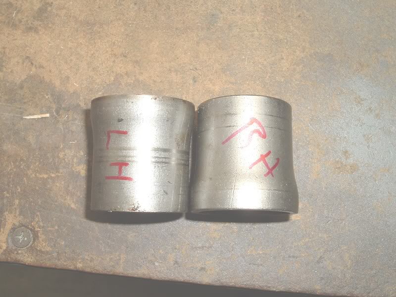
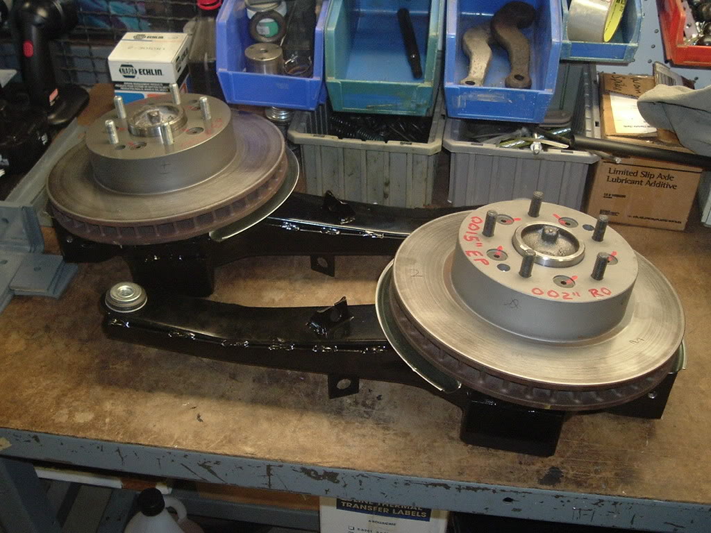
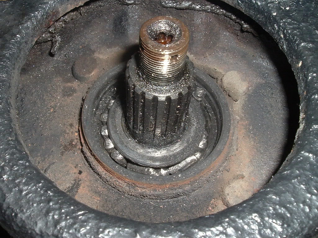
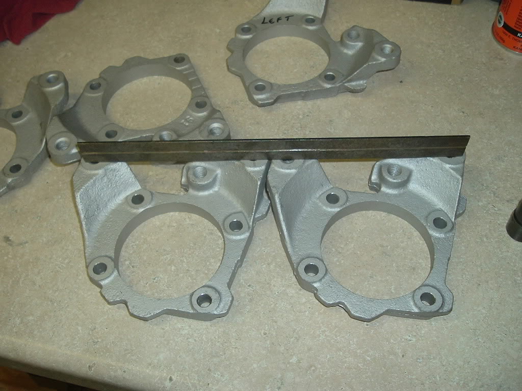
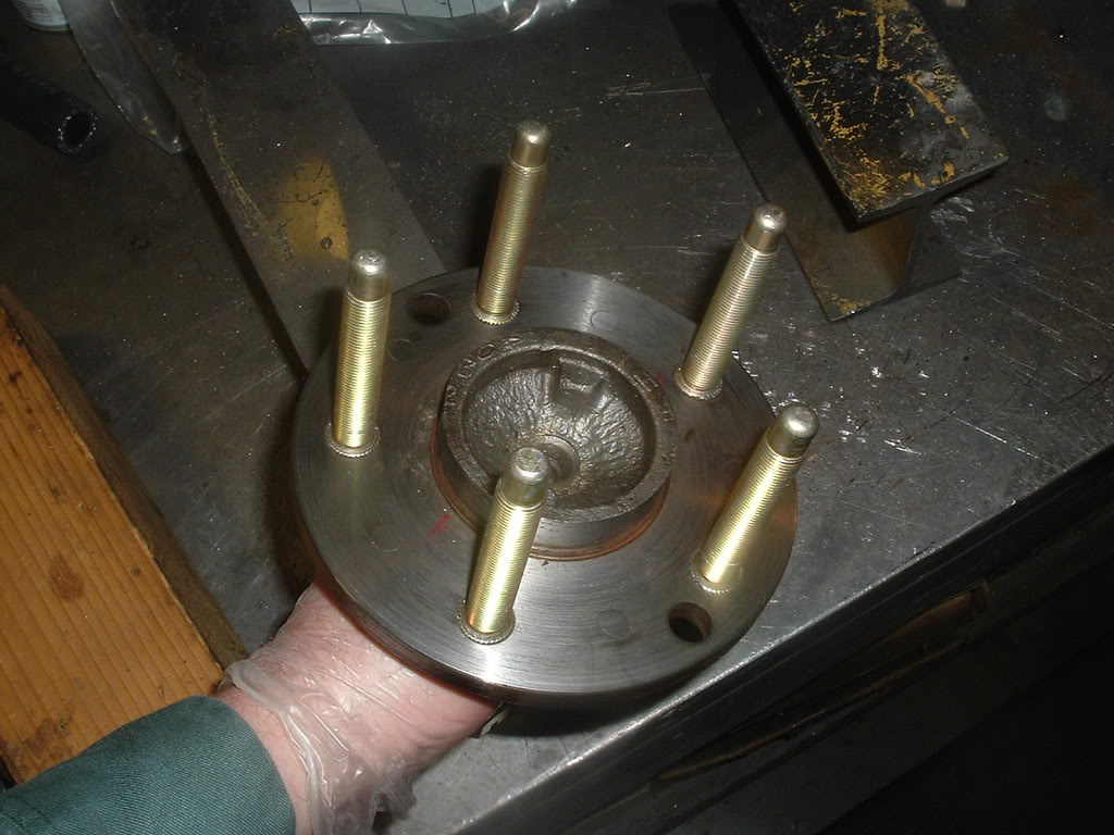
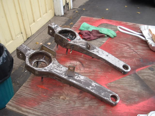
Here are what your arms may look like once you get them out. I always rebuild them off the car but they can be done on the car. I would never do it that way unless I was stuck out of state on the road.


LeftArm.jpg

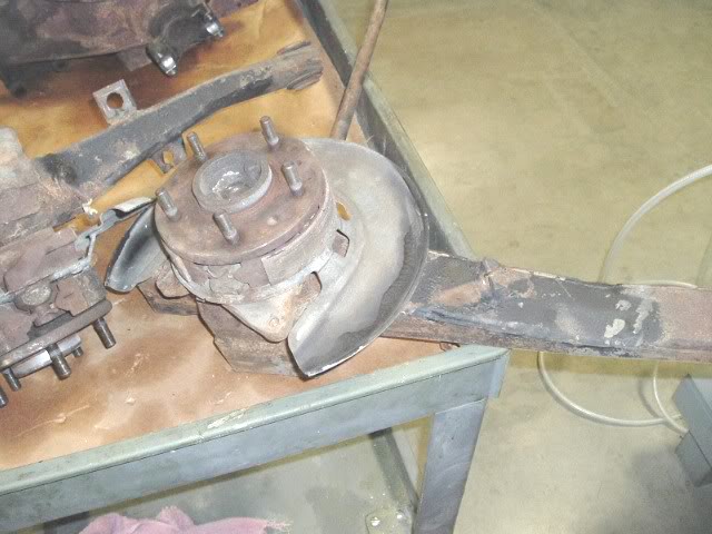
Here is a 64 arm. Remember the 63-64 and some 65's had drum brakes.


LHoutarm.jpg


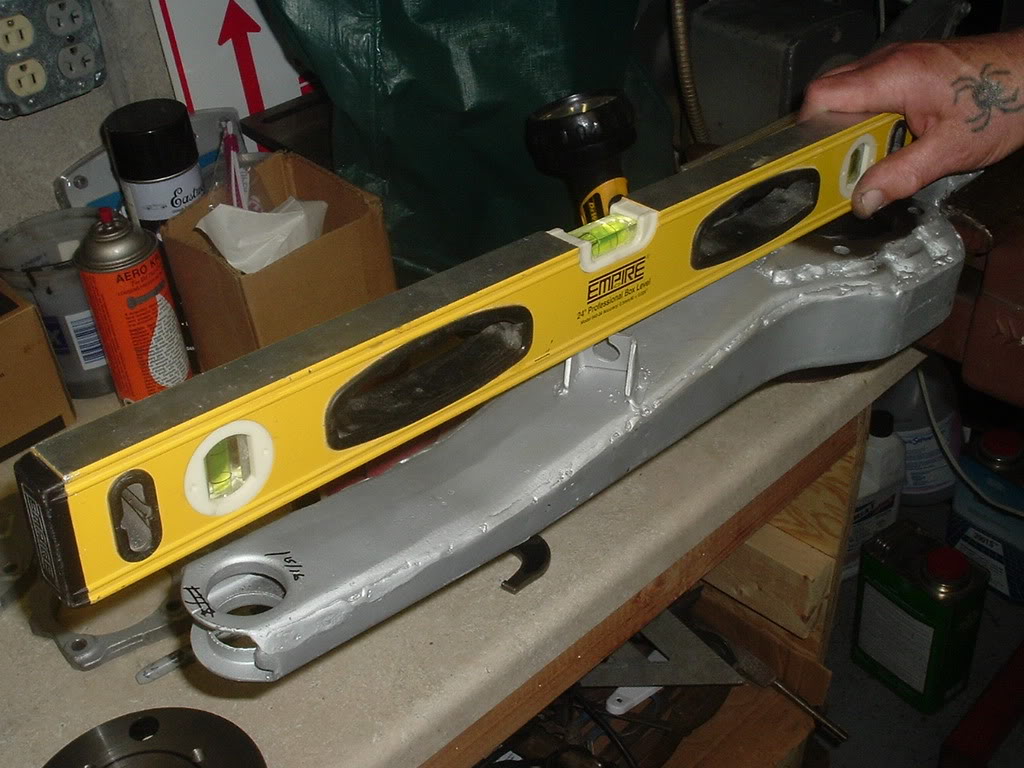
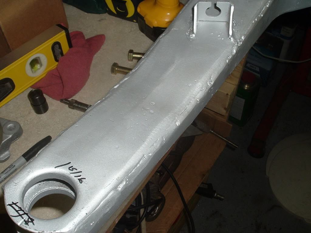
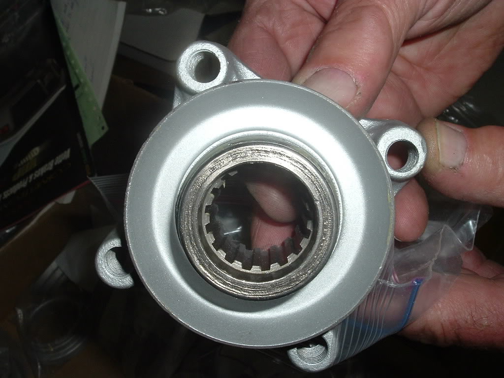
Look them over for rot, being bent, and look at the front bushing for dry rot.


LHoutbushing.jpg


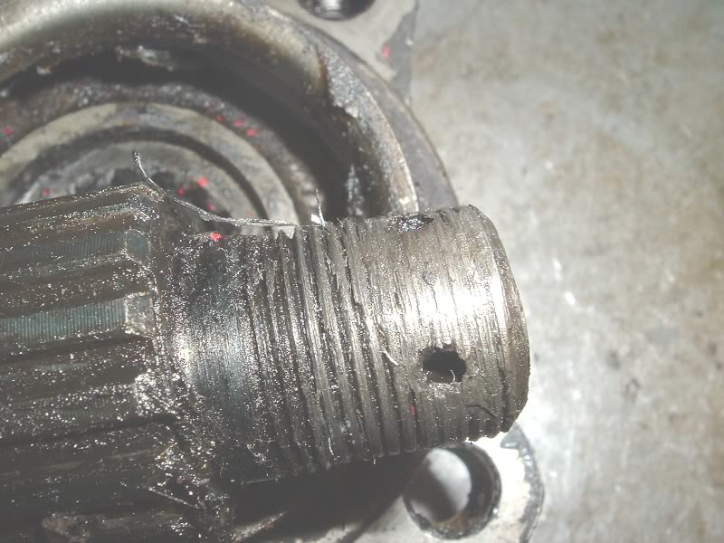
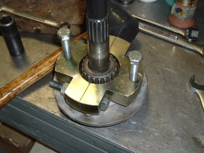
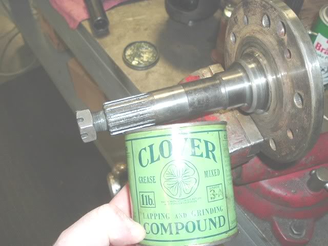
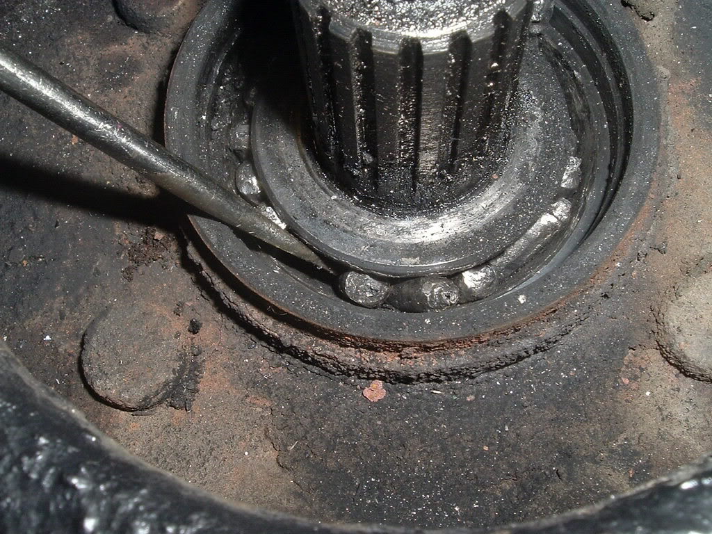
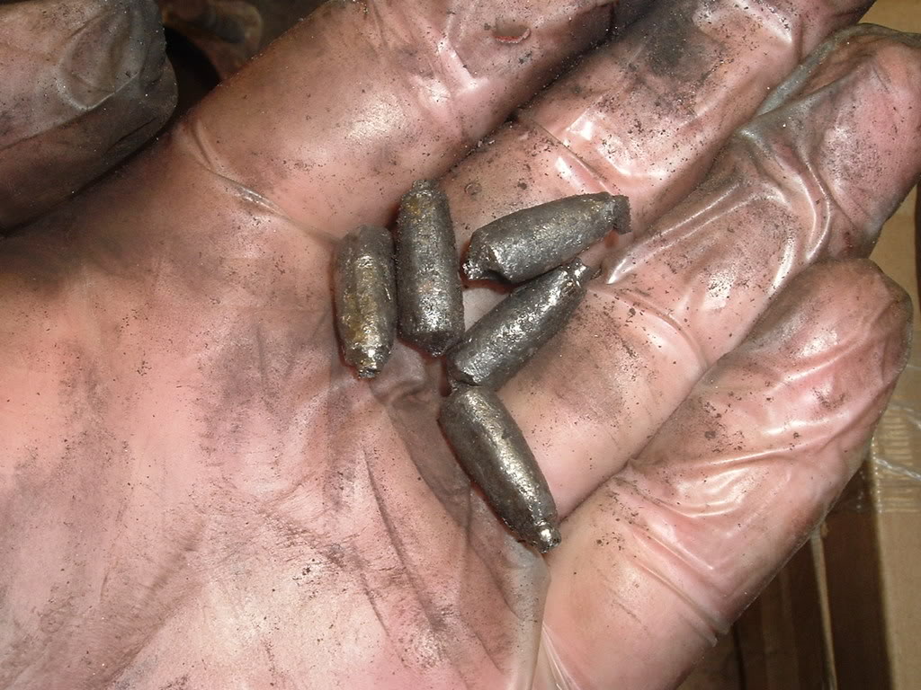
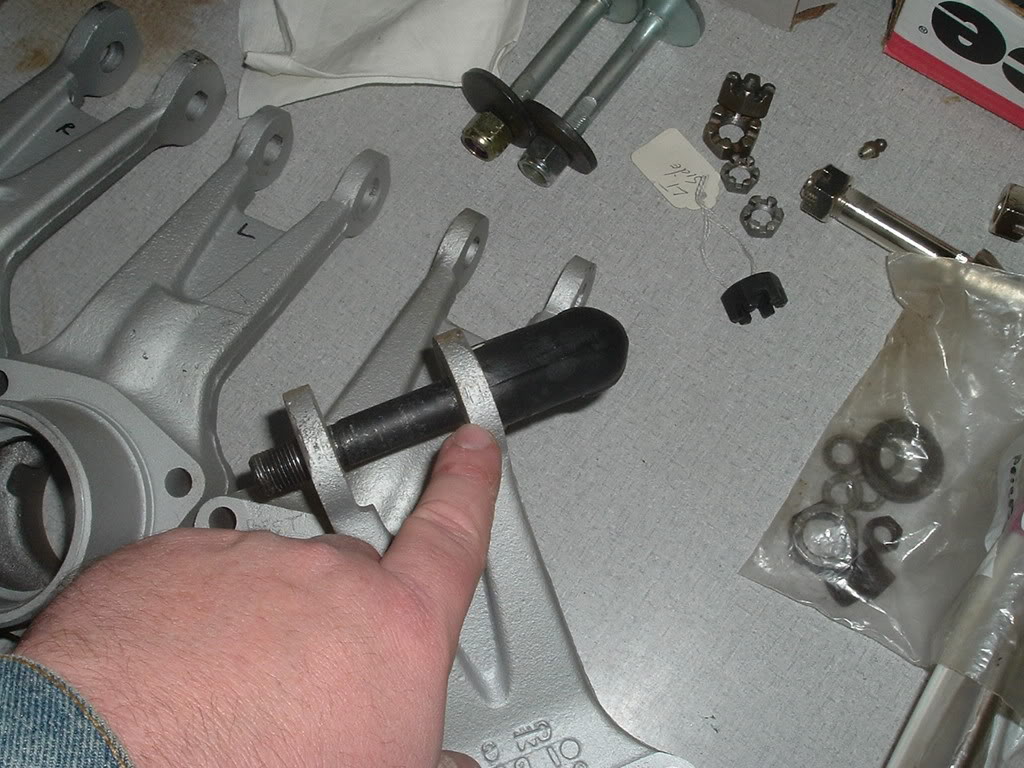
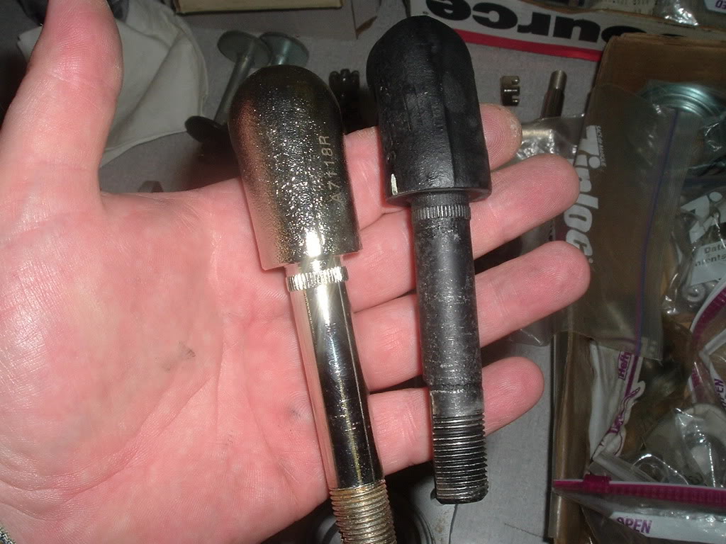
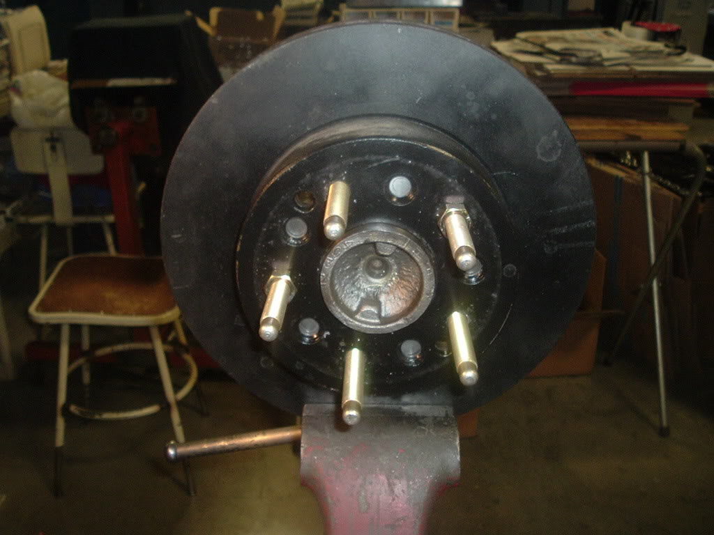
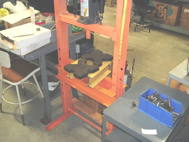
I use one of those spindle protectors and either press or hammer the spindle out. If you hammer them out place something to catch the spindle. Don't worry about the bearings as they will be replaced anyway. If you have one that is really rusted the press and some heat may be the only way to go. Also the spindle nut should come off and the tool thread on without a problem. Many times these have been worked on before and the threads are already shot and a new spindle is needed.


presssetup.jpg


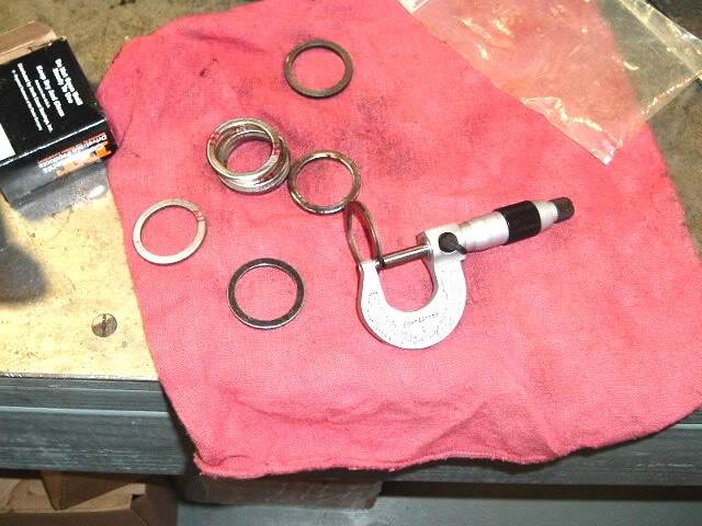
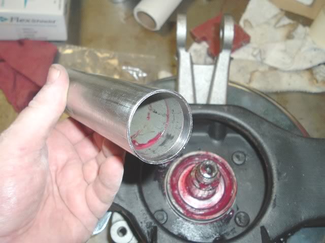
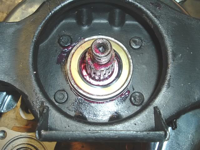
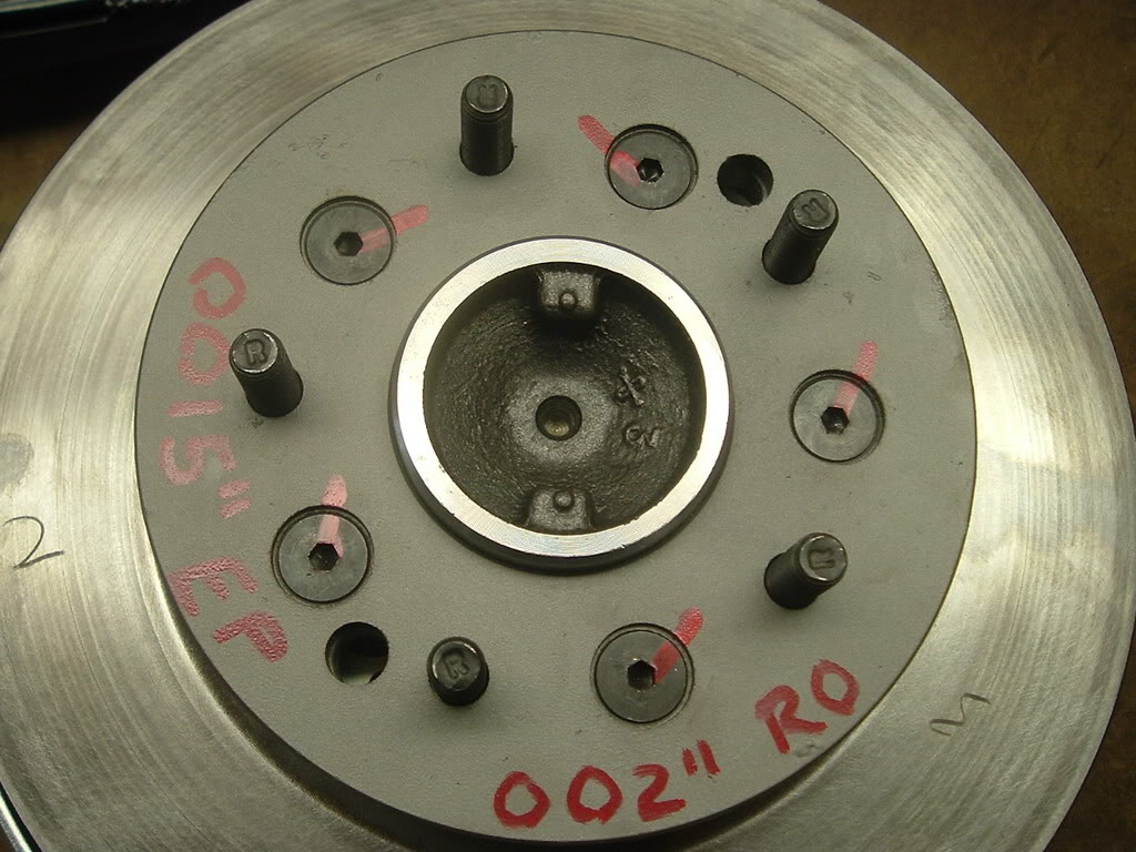
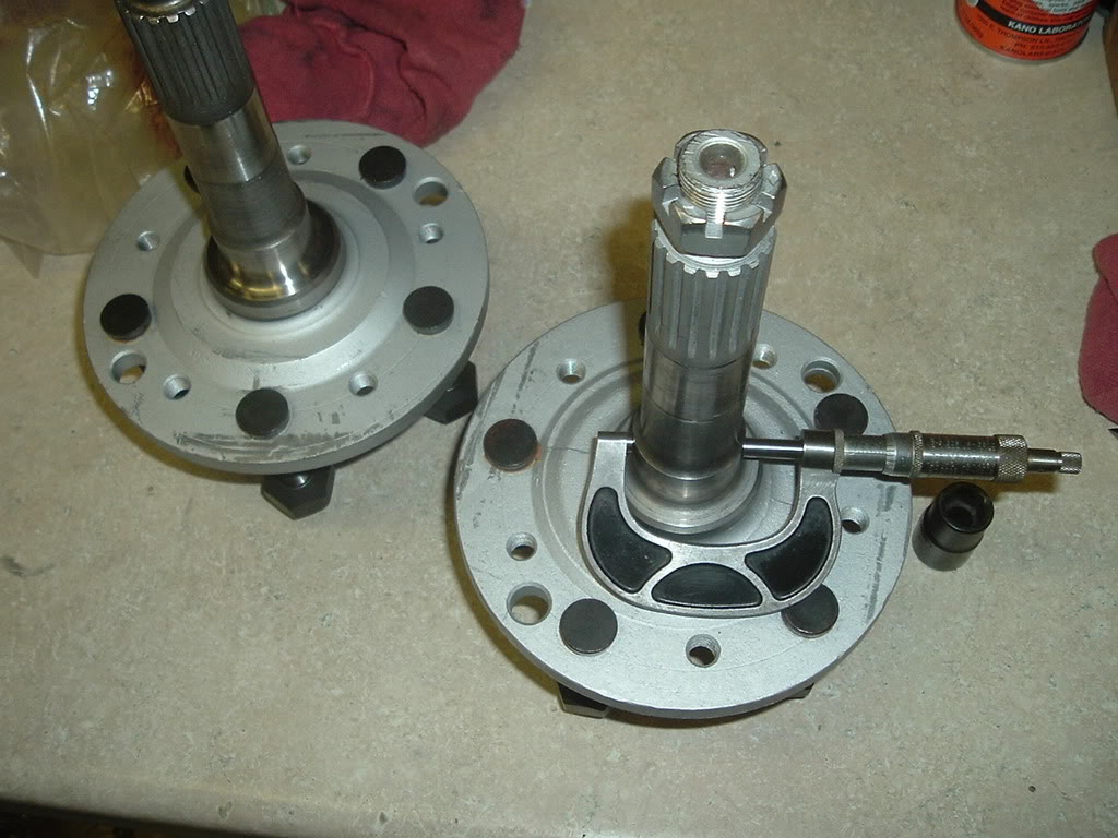
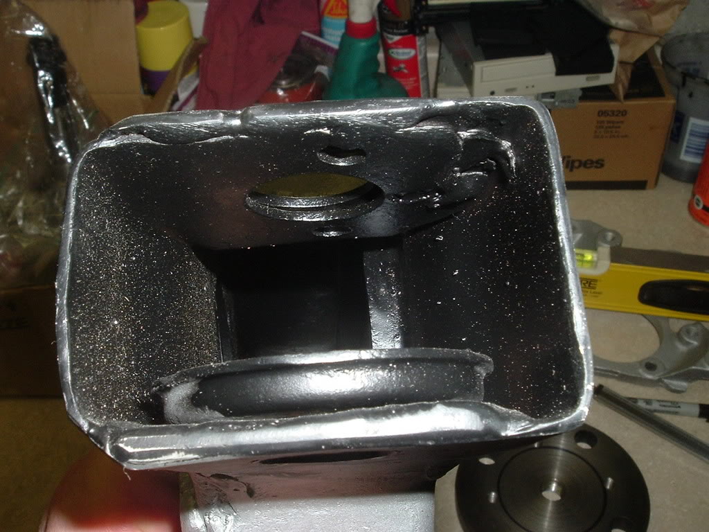
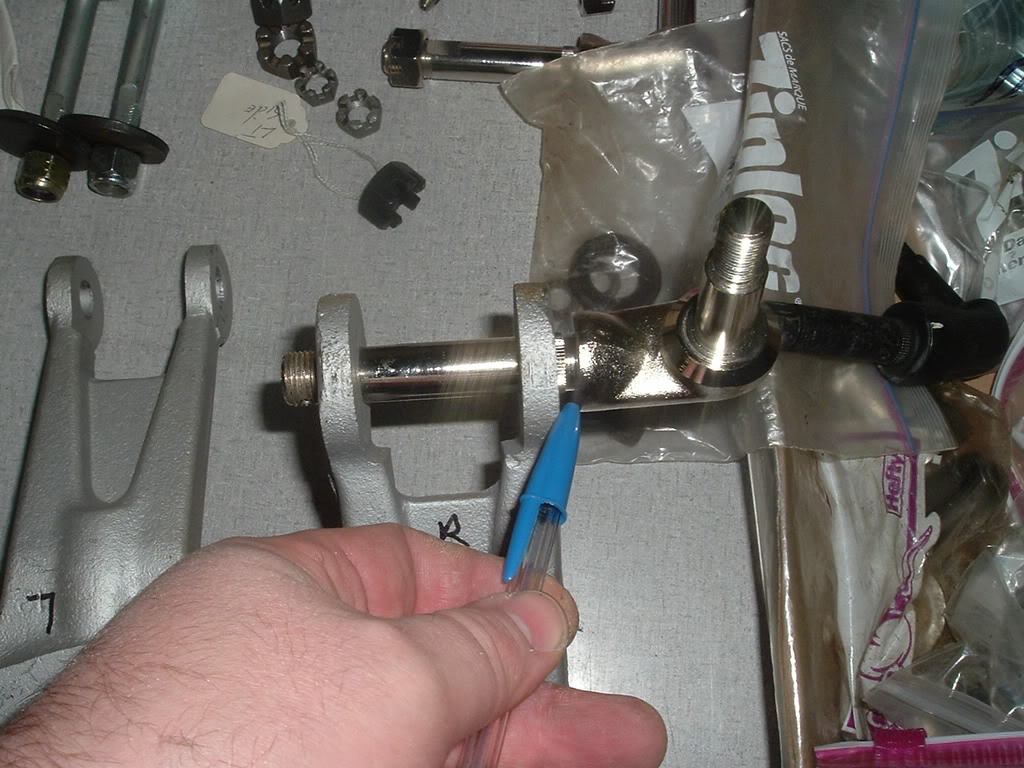
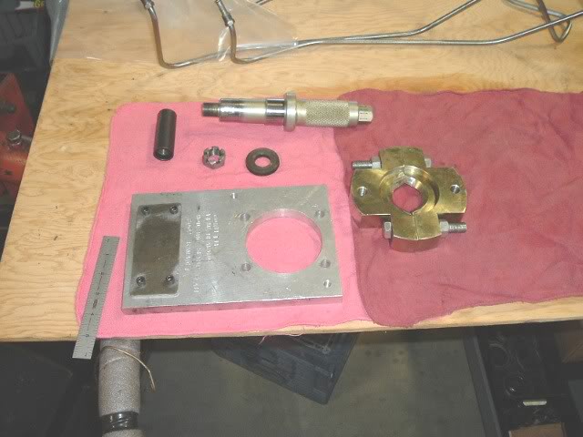
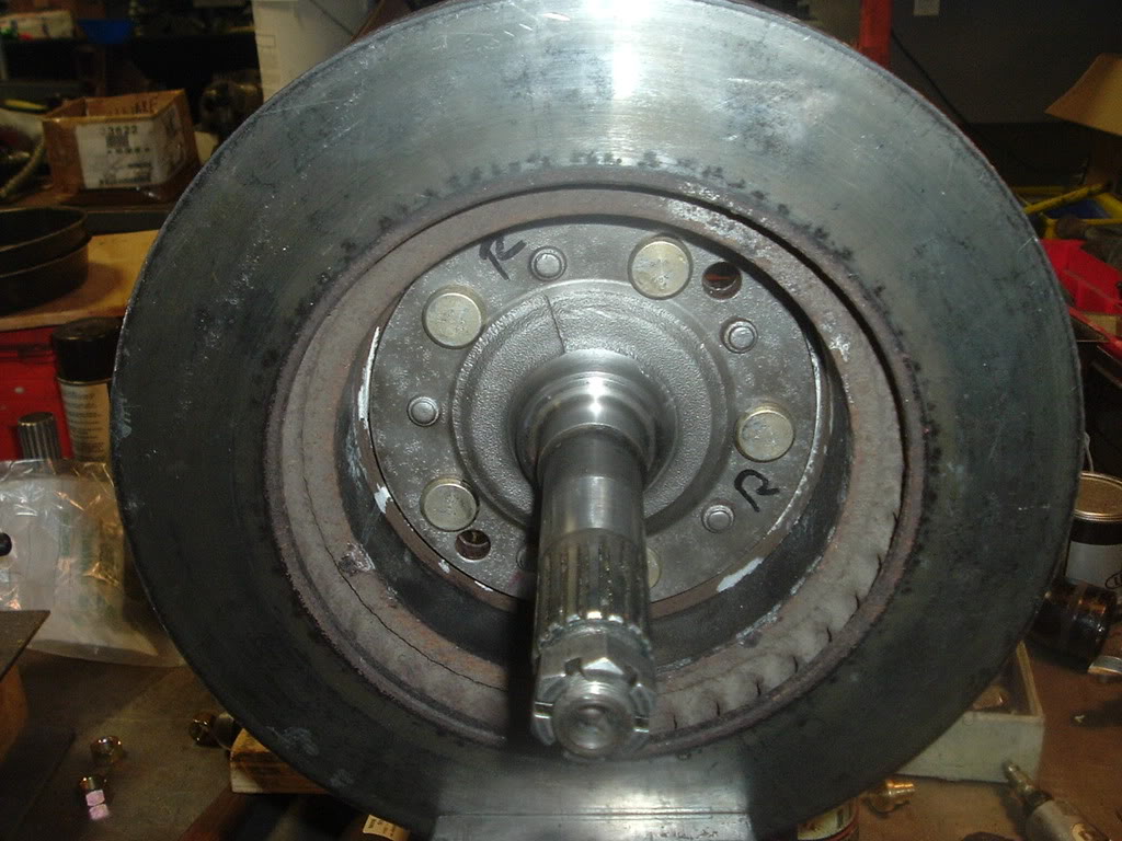
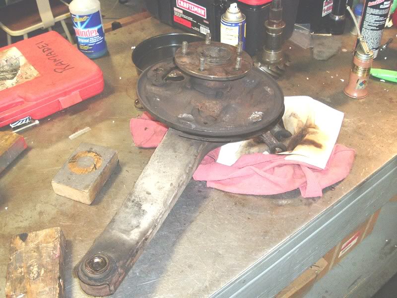
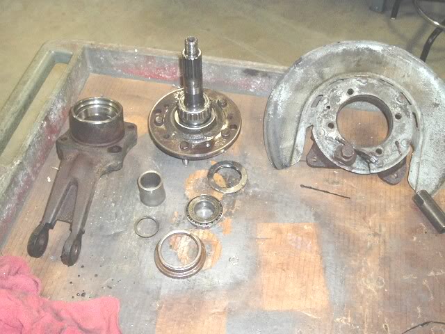
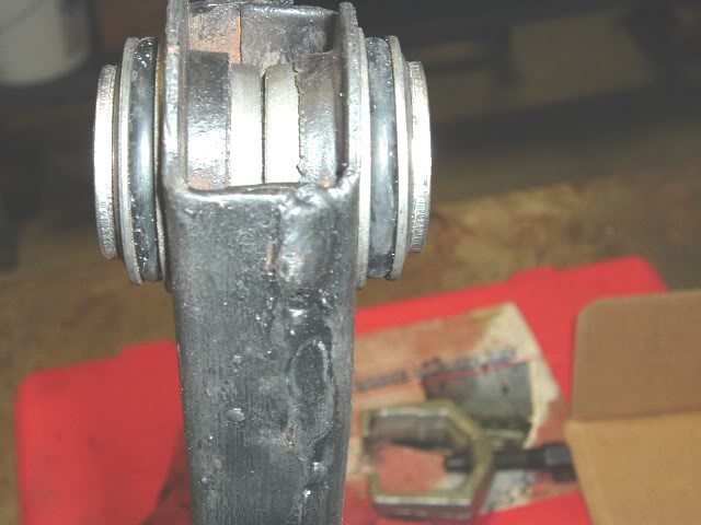
Here we have parts to one arm apart and cleaned up for inspection.

RightTarm.jpg


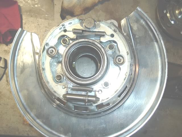
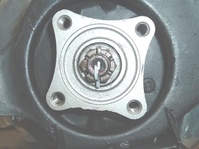
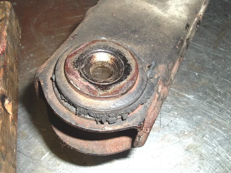
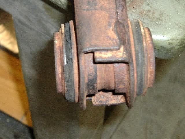
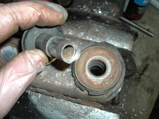
Here I found someone was in here before and installed the outer seal backwards.


revseal.jpg


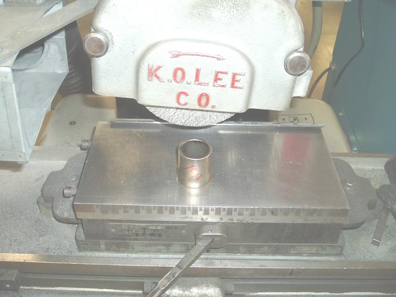
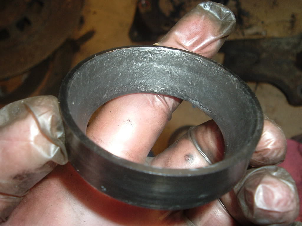
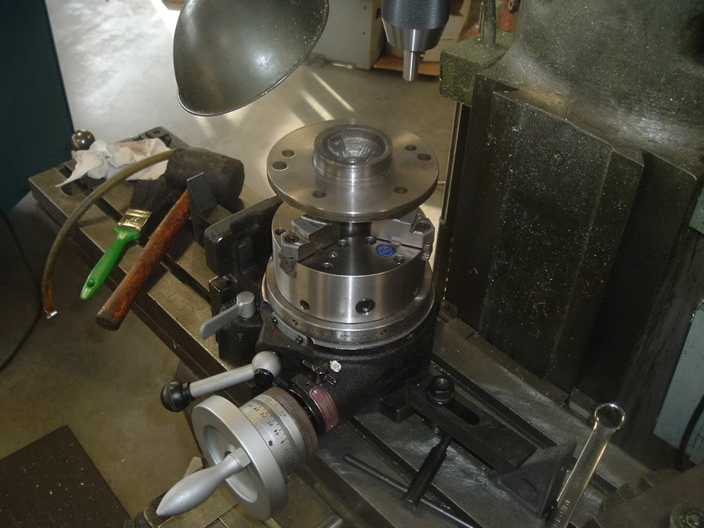
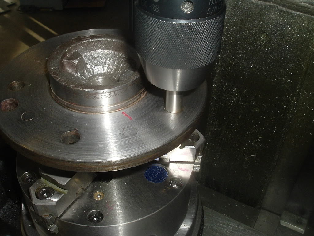
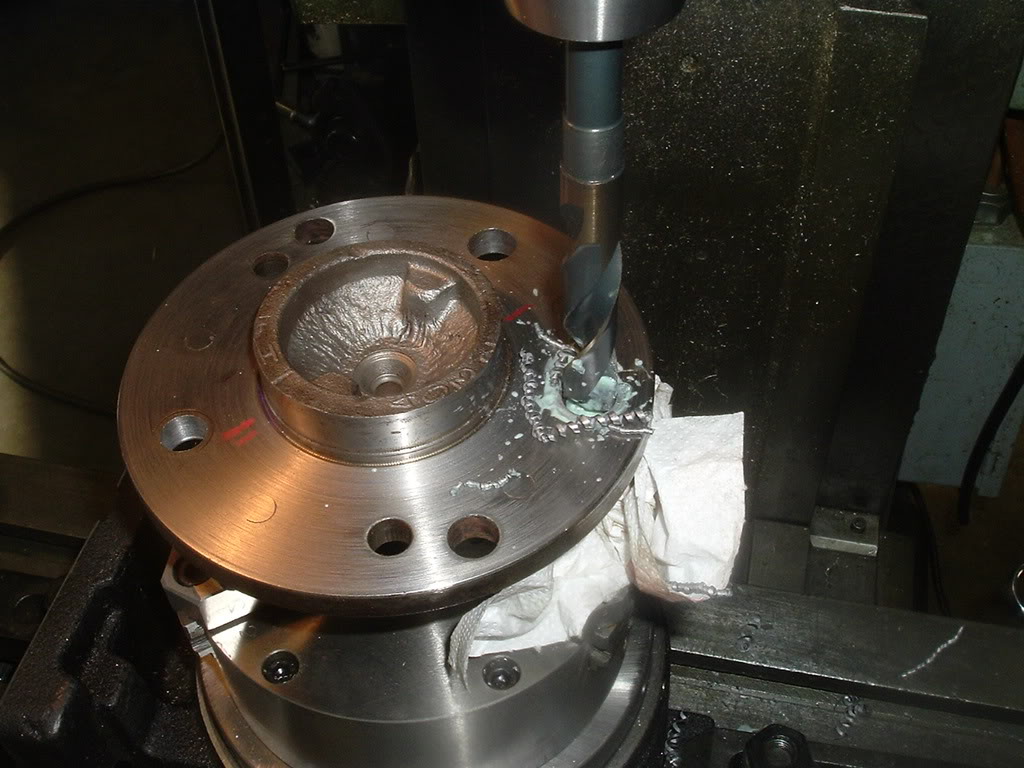
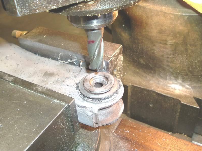
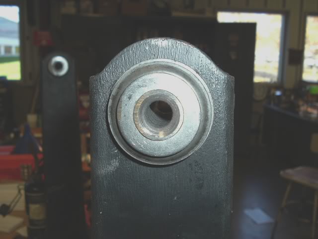
Once stripped down, I remove the front bushing

Frtbushing.jpg


Drill the flare out and use an chisel to remove. I used to put these in a Bridgeport mill but a large step drill works as well.


MillBushing.jpg


removingbushing.jpg


Sleeveremoved.jpg


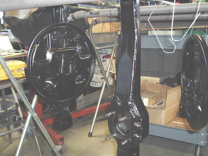
With the arm apart, I blast them to the metal and POR15 prep and paint them. I top coat with a satin black.

strippedarmsready4paint.jpg


SatinBlk.jpg


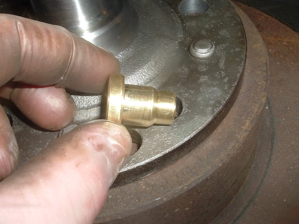
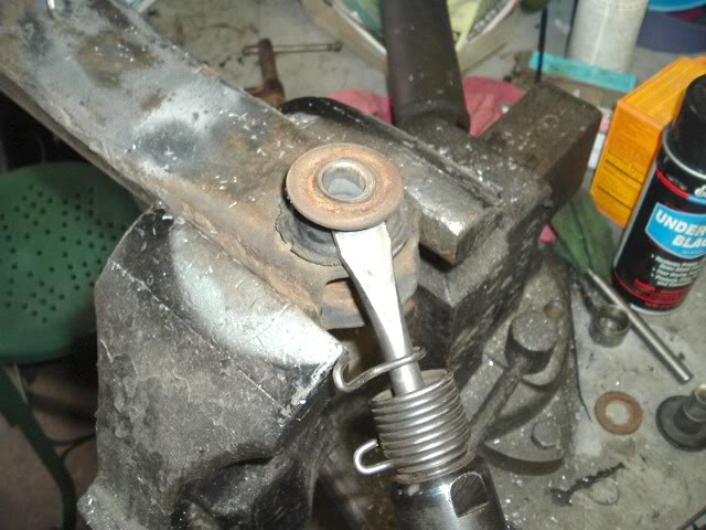
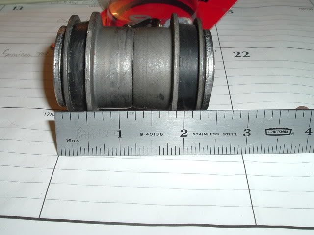
I use only rubber bushings, no poly for me. The rubber have to be compressed and then flared to correctly install them. I have found all kinds of crap work in this area, some have even left them unflared!

newbushing0001.jpg


Here is the tool I made. Works good. There are a few on the market, some good -some junk.


Flaretool.jpg


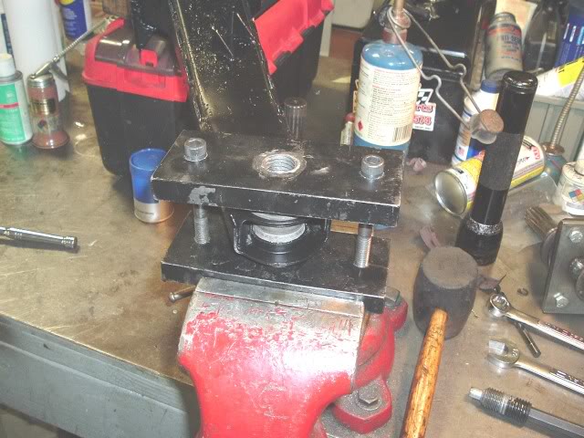
Here are what mine look like


bushside.jpg


tarmbush.jpg
 
Next look at your spindles. If you have threads like this replace the spindle.


RHthreads2.jpg


Ok on to Bearings. I use only Timkens and CR/SKF seals. I could debate the fact other bearings are just as good or Timken are not made here anymore. You decide what you want. You can save $20 using imported bearings if you want. The Timkens I have are still stamped USA and I'll pay more for them.


parts.jpg


The book calls for .001-.008 endplay in the bearings. I set them to .0015 -.002 +/- .0003" That is correct 3 tenths. Others may tell you otherwise which is ok for them, remember this is how I do them.


0001.jpg


Here is the fixture I made to setup the endplay


CKGendplay.jpg


Now here is the deal on this job. IF you want the BEST job done use a surface grinder to dial in the endplay. If a guy tells you he can dial in .002 endplay with just the common shim kits - walk away. I have never had one shim I could use without grinding it to size. Also you see those kits with the new spacers in them, total waste of your money. Unless the original spacer was burnt by an idiot with a torch they are still good and they do not fail in service. The thing with them is they are not parallel finshed. I always parallel grind them before even setting them up in the fixture. It is not uncommon to find them out .005 or more. This can change the endplay you setup on the setup tool to the final press on install.


Spaceside.jpg


Grindface.jpg


OK with the spacers ground and in the fixture. I use a large shim to start. I have one that I use as a setup shim. I torque the tool to 100 ft/lbs and see how much endplay I have. Then grind a new shim to size and double check it. I only use light spindle oil on the bearings- no grease until you are done and ready to install the bearing in the press.

Use a micrometer over a dial caliper for this job. If your guy thinks a mic is a C clamp - walk away. Or even better as reported in a leading corvette magazine- "so and so has been rebuilding rear bearings for so long, he can feel the correct endplay"


CKGshims.jpg


When the endplay is set I install the prepped and painted parts on the arm.
It is much easier to install the parking shoes with the spindle out of the way.

PBshoes.jpg


Now before you install the spindle you have to remove the outer bearing. This should be done before you get to this point. Remove the bearing, clean the spindle, check the journals, replace the studs and I face the flange in a lathe as well.


brgpuller.jpg


Now if the threads are rolled a little you may be able to save them. I have a thread forming tool, thread file, lathe, but you can use the "old school way" of using an old nut and some very fine lapping compound to clean them up. BE sure the threads are good and you use a new nut before you get to the bearings.


cloverleaf3A.jpg
 
OK now we are up to assembling everything right?

The spindles are cleaned up, the arms painted, bushings installed,and bearing endplay set. One of the spindle preps I do is to remove the rivets and tap the hole 3/8-24. We'll explore this more when I get to the rotors.

Ok, so grease the outer bearing, I use Mobil 1. Install it in the housing, install the outer seal- I use Ultra Black on the OD and grease the rubber seal ID.
Place the spindle in there - it will be loose. Place the spindle on a support and install in the press and press on the outer bearing. Pack the inner housing with grease but leave room for expansion. Install the spacer and shim- you did have them parallel ground didn't you!:smack

Grease the inner bearing and put it on the spindle. Transfer to the press again and press the inner bearing on the spindle. Bring it back to the bench and install the inner seal- again RTV on the OD. I then usually re-use the shield and loctite it in place. With the yokes, I again grind them, clean them up and chase the threaded holes.


EMTtool.jpg


Innerseal.jpg


Cotterpin.jpg


Torque the new nut to 100 ft/lbs and check the hole for the cotter pin. If needed you can tighten some more and install the new pin. If the hole is out a lot I grind the nut face to index it on the spindle. The spindle should spin snug but not tight. If you need two hand to rotate it there is something wrong. At .002 endplay you can feel movement,not much but you can feel it.
If something is wrong at this point you have to start over. Now here again is where the job differs as I have seen spindles so tight they could not be moved and so loose the endplay was over .004" Where did I see these works of art? - on tables at Carlisle for sale.


Now I countersink the rotors and bolt them on to the spindle flanges with 3/8-24 flat heads. Then setup an indictor and check the rotor runout. It doesn't matter if you have original rotors, new USA or new imported they will have runout. If over .002 I shim them to .000-.002" You can go to .003 ok. I wouldn't use anything over .003 and you should not accept anything other then that.

I do not like the procedure of using just the lug nuts to hold the rotors on. The runout can change everytime the wheel is removed that way. Many do it this way, I don't. I want the runout to stay where I dial it into.


FInishedarms017.jpg


RHfinished.jpg


OK so what do you think and did I answer your questions? Does the job still seem tough once you have the tools and procedures? Doing it my way will take longer but do you want this job rushed? Be honest with yourself and think it through before starting.
 
I'm doing a 65 now and one arm has locked up spindle bearing. Thought you might want to take a look. The smell was something awful too. The spindle is wrecked but the support may still be good. I'll clean it up and mic the ID to see if the race spun and bored it open.

Here is the inner bearing with the flange off. Looks pretty good huh:laughing:

burntrollers.jpg


Siezedinnerbrg.jpg


Here are what's left of the rollers. These were the original Hyatt bearings.


damagedrollers.jpg


Here is the race. Look and you'll see it's coated with welded on roller metal.


innerracerollerwelded.jpg


Here is what is left of the bearing, the inner race.


scoredraceandspindle.jpg


Spindle is done.

Innerjournal.jpg
 
Ok to complete this thread. It was mentioned I left out things among some other statements. Since I don't do arms everyday and don't stock them I had to go over to my buddies to get some more pictures. I didn't have anything in the shop.

So where did we leave off?

Spindles
If the races were spinning on them they would be marked up or seized. It would be obvious. They should be checked for thread damage, journal damage and the journal diameters may have some minor score marks where the inner bearing and spindle separated. They have center drill holes for those of you who may want to true them in a lathe. You'll have to remove the studs of course and I would replace them if you do remove them. I leave them in if there is no damage as they are better then the some of the current aftermarket studs. For 63-64 spindles, they use a shorter stud. I have faced the longer ones in a lathe to make them the same length as the originals as that is what the owner wanted.
Spindle Journal diameters, these are the spec's have. Taken from my old original and new spindles.
1.376 +/- .0005"
1.188 +/-.0005"
If you want the best job then you'll have to rivet or bolt the rotor and spindles together and kiss cut them in a 14" or large lathe. I bolt and shim them as my lathe is not that large. Also since this threads intention is for the DIY owner most will not have a lathe in their garage.


dudow009.jpg


Here is a scored journal and the spindle was replaced.


scoredraceandspindle.jpg


Here is a new spindle with 1/2 studs installed. I'm going to set these up in a week or two.


dudow011.jpg


Caliper Brackets.
I have not build a jig for this as my recent critic questioned. I have seen some damged from using one of those spindle presses. Most times I'll lay a striaght edge on the ears. I suppose I could set them up on our comparator and check the dimension from the machined face to the machined ears, but again given this is for the DIY owner I doubt they would have that inspection equipment. I use a common sense approach to this work. If the owner had caliper issues or alignment issues they would be looking at these areas for a problem. I may be wrong with my assumptions though.

dudow012.jpg


ARMS

Ok I left a lot of arm information out, so I'm told. I was vague when I said to look for rot or damage, again as I was told.
Look over the arms in the pocket area for rot. Look at the seams on the end for separation. Look at the flat plate welded to the arm a lot of times rust start in between the layer and causes them to separate and expand. Look in the ID of the large hole where the support mounts. Look at the studs, if they are not rusted and the threads are good I leave them alone. I'll chase the threads as I do the other threaded parts.

I have not made a fixture for this either but all that would be needed would be to run a str edge with the arm in a fixed position to measure the gap between the end and reference line. I use a str edge and the dimension I always used was 1.875" Mike who I trust 100% stated the arms are 1.920" I was off .045" I have never found this dimension in any formal manuals. The tolerences are not as tight as others and some arms can be rebent if desired.
If the arm is bent beyond .200" - .250" I look for other signs of damage and will usually replace them. One set I did was out .375 because an alignment shop purposely bent then trying to align the IRS. Another arm I had in was pounded out of dimension-- not sure how that one happened as the rest of the arm looked fine and had no rot. Str edge and scale or caliper will be all you need.


dudow014.jpg


dudow013.jpg


You can also weld the ends and length if you want. I look at the ends more then the length, but if you have a welder at home go for it.

dudow016.jpg


dudow018.jpg


SUPPORTS

I look at the support arms to see if there are any signs of damage from hammering out the shock mounts. I look in the bores for signs of race damage. I clean, blast and POR15 them. Be sure there is no left over glass bead or dirt in the wells. Fit a shock mount in them. Check the hole ID for signs of egg shape or damage. .640" If you have your shock mounts out check the fit. If the knurl is worn they will bottom out without any resistance. If so I replace them. New knurl OD .659"


dudow021.jpg


dudow022.jpg


dudow023.jpg


Spindle Flanges
I parallel grind these. Sorry, that crap of using sand paper and a flat block just doesn't wash with me. These usually have beat up faces that mate to the inner race of the inner bearing. I grind all mating surfaces for a flat fit.
You can see here what they look like.

dudow024.jpg


I think that covers areas that I "left out" from the previous posts. I welcome all comments on my work when the comments are directed at the questioned areas, not any underlying motives. It's clear to see when someone wants to add useful information for the good of all, like Traccdog did.

I will not apologize for any of my posts that might be considered "harsh" especially if that person has information that could be added without instance to benefit the group of C2 & C3 owners we have gathered here. If a vendor has a problem with me then they should step up and contact me. As mentioned I never named anyone, I left that up the owners who had the work done- some of which I had to correct.

This job can be done at home with some limited outside machine work. Just be honest with yourself on your capabilities. If the car owner decides to go outside for service they will have a good idea what is involved with the job. There are certainly a few places that do this work, my threads have never been posted to build jobs for myself. Along with possible local places,Traccdog, Bairs, Ikerds, etc all can do them. There are really no secrets to this work,BUT not all jobs are done the same. You now have the facts on the jobs to make an informed decision.

Here are the tools I use along with a KO lee surface grinder.


rearbearingtools0001.jpg


I have the spindle press and made a spindle install tool. I have never used either one yet. Here is the spindle install tool I made. If you want to make one the threads are 3/4-20 not a common thread so if are planning on getting a die you'll have to go to an industrial supplier. figure about $65 for a die and $25 for a handle.


spindleinstall2.jpg


Good luck, no one will treat your car as you will.:thumbsup
 
I'm setting up some bearings and installing 1/2 studs for a buddy.I just got to doing this job and wanted to play around with the new index head we got. I spent more time aligning it then using it.

I used the ARP bolts, the FORD ones, (1/2-20 x 3"). The kurl is just under the flange thickness. I stepped up the drilled until I got to the 39/64 bit. I set them up in a Bridgeport, in back gear, and they cut no problem. I started them with a hammer and then pressed them in. I used 2 old rotors for an alignment fixture and this worked good. You have to open the "fixture" holes up, I went to .515".

I have not done this with a hand drill and suspect it is a bit more of a job that way. I also wouldn't go with the ARP recommended 005" hole undersize. The 609 hole is 016" under and the press was tight but not bad when using a press. I could have hammered them in as long as they went in straight. I suppose I could have made a better hole alignment fixture but I usually use 7/16 stock studs when needed.


indexfixture.jpg


dowelpin.jpg


609bit.jpg


The studs heads are wide and come very close to the chamfer on the back of the spindle flange. I made up this dummy plug to check the fit. It was close so I used a dremel to grind in a chamfer on part of the studs to clear the flange.


dummyplug.jpg


chamferbolt.jpg


holefixures.jpg


installedstuds.jpg


RHSpindleinner.jpg


RHspindleouter.jpg


Now on to setting up the bearings.
 
Back
Top