81 Malibu "Uncaged" Performance Therapy project

Since we were out of the correct size for the new exhaust seats (and it was a holiday weekend) I jumped over to working on the block a little. I had scored a set of breather tubes for the lifter galley out of an engine I was stripping for scrap at the shop a few weeks ago. Someone had blown up something and swapped all their good parts over to a new shortblock and left the old one with the tubes in it. They're not the fancy looking aluminum ones but will do the same job so they're perfect for my no budget build.

The block needs to be threaded in order to insert the tubes and plugs so while I was at it I threaded the end holes for plugs also. To thread the holes first a tapered reamer is used on a drill to chamfer the top of the hole so its easier to get the tap started. Then cut threads with the tap. Because these are tapered pipe thread the depth is checked on the first hole and then the tap is marked and the rest are tapped to the same depth.

Here's a pic of the reamer and tap . And then a pic of the vent tube and a plug. Bottom pic is the end of the block where plugs get installed.

Uncaged357012.jpg


Uncaged357013.jpg


Uncaged357011.jpg
 
I love the posted pictures, ,especially the clear posted ,detailed pictures, as I'm sure many of the readers on the site rarely or never get too see the machine work being done! and few guys have either watched it being done or done the work themselves
and for the newer guys who might be reading this thread

while Im sure many of the guys looking at that cranks rusted journals would assume if its that rusted it might be trash, its surprising how little polishing (AT TIMES) is required to bring back a decent bearing surface, and yes you generally need to verify clearances and journal taper and measure bearing journal roundness but in many cases a bearing thats slightly tighter can match the journals required clearances without going to a .010-.020,.030 under size.
Id also point out that occasionally guys forget to clean out the cross drilled oil passages resulting in metallic debris embedded in the bearings so clean carefully after any crank journal polish work
plas5va.jpg

14653.jpg

55798-01-200.jpg

nozzle.gif

related info, worth reading thru

viewtopic.php?f=53&t=9214&p=43456&hilit=polish+journal#p43456

viewtopic.php?f=53&t=9955&p=38385&hilit=polish+journal#p38385

viewtopic.php?f=53&t=2726&p=26599&hilit=polish+journal#p26599

viewtopic.php?f=53&t=852&p=21611&hilit=polish+journal#p21611

viewtopic.php?f=50&t=7604&p=25728&hilit=number+stamp#p25728

viewtopic.php?f=53&t=204&p=12785&hilit=number+stamp#p12785

viewtopic.php?f=50&t=1738&p=4333&hilit=number+stamp#p4333

viewtopic.php?f=53&t=247&p=7387&hilit=number+stamp#p7387

viewtopic.php?f=53&t=1478&p=3331&hilit=number+stamp#p3331

viewtopic.php?f=53&t=2726
 
Last edited by a moderator:
TonyHuntimerRaceHome said:
That's fricken cool! I knew I should have entered! DOH!

Congratulations! Nice product shots too!

Tony Huntimer
RaceHome.com

I gave away almost all of the Hot Wheels stuff. My bud that took the pic I used for the contest, workers at my local tire, paint, parts, and machine shops as well as friend that helped me get the Firebird project going almost 20 years ago, a family member, and a couple Hot Wheels fanatics on a forum I frequent all got goodie boxes. I only kept a couple for myself. It was fun giving them out! And they all loved getting them.
 
My fault for not explaining previously and the same question came up on other forums. The whole reason I'm posting this stuff is to help those of us who'd like to know more about the machining and building process. The guys that know more than I ever will who read this will surely call me out if I present something incorrectly or where there are differences of opinion of what is considered "the correct way". Which would also be fine. Always open to suggestions! And please anyone, if you have a question ASK, others probably have the same question as was the case with "vent tubes". Below I copied and pasted part of vent tube discussion from when it came up on a Malibu forum.

1981Regal said:
What do the vents add to the setup? Seems like its a weak point for the block. Just thinking aloud.

The vent holes are factory drilled. Installing vent tubes prevents oil from dropping through increasing windage on the crank so it's cheap horsepower by reducing parasitic losses.

Doober said:
Is this a street motor? My understanding is vents are generally better left for race engines, and the extra oil on the camshaft helps keep it lubricated better for everyday street use.

I worked at the shop tonight and just happened to be decking SBC marine blocks so we had a discussion thanks to your question Darren. The concensus (of the engine builders) was that GM drilled the holes to vent the crankcase, not to provide oiling, and that the oil supplied to the cam and lifters was more than enough. Plus there's oil spraying around from the crank, rods and pistons. Having the holes blocked off gets the oil to flow down the holes in the corners and back to the pump quicker and with less aeration than if it goes through the vent holes and drops onto the rotating assembly, with the added benefit of cheap power. The factory probably didn't install vent tubes because it would require a threading operation, installation procedure, and additional parts. The additional power probably wasn't worth it to the number crunchers when comparing cost and potential liabilities to the power gain.

The street/race question concensus was that there is no down side to using the vent tubes so why not run them on the street if you're building a high performance engine. All the race engines built at the shop and most performance builds for the street or marine applications get vent tubes. Stock rebuilds for repair garages and "restoration" engines don't get them unless requested. Also it's generally accepted that not all of the vent holes are necessary for most SBC engines so many shops will buy a set of 8 and use them for 2 engines by installing a tube in every other hole and installing plugs in the other 4 holes. I took 8 of the cheap pipe style ones out of the engine I was stripping so I'll just use them all.

New post
Since I was pressing wrist pins out of connecting rods at the shop I figured I'd get mine apart so they'd be ready for some work I want to do to them. The block had been bored to work with a slightly used set of .040 over forged pistons my buddy Mike at Mikes Automotive Machine in CT hooked me up with long before I moved south. It's been so long and with all the miscellaneous parts I've had and moves I made etc we figured we should double check the cylinder bores and pistons to be sure everything was going to work out cool. No sense taking the piston/rod assemblies apart if they wouldn't work. So here's a couple pics measuring things.

001-1.jpg


The cylinders came in at 4.041 and the pistons were around 4.0398+ so we'll be right in the ballpark of the recommended .0015+ recommended by TRW after the cylinders are honed. For the experienced/knowledgable guys I'm aware that these pistons were prone to cracking in the skirt curves when run too loose loose back in the day before they switched to the shorter skirts and checked these. They were a gift so although they are an older design they're better than what I would have otherwise! Thanks Mike!

003-1.jpg
 
For those that have never seen it done, this is how we remove stock style wrist pins from piston/connecting rod assemblies. (Later on in the thread I'll show how they're installed)

The pin is fitted with an interference fit in the top of the connecting rod and it takes a lot of force to push them out so a press is used. A support is placed under the side of the piston (different supports for different pistons) with a hollow base support below that to provide enough height to push the pin down. Then a tool that fits inside of the wrist pin with a shoulder that will push the pin is inserted. The tool is smaller in diameter than the pin so it will fit through the hole in the side of the piston. In the bottom pic the wrist pin is still stuck in one side of the piston but can be pulled out by hand. The "tight" fit is in the top of the connecting rod.

005.jpg


004-1.jpg


006.jpg
 
Shops mark things that are supposed to go in a particular place,order, or match up with machined surfaces.The rods had markings from other shops on them (in this case stamped letters/numbers and indentation dots) so I lined them up in order and did them the way we do them in this shop because I may loose some of the other markings as I work on them. I zipped the lock side of each rod with a disc and etched a number in each with a dremel. You may be able to see the 7 etched in the rod on its side and dots on the bottom of some of them. After that I removed the caps and bolts so I can start grinding them.

008.jpg
 
thanks so much for posting these pics john, its really interesting to see what goes on behind the scenes at the machine shop and the various processes the parts have to be put thru just to get put together and function again. alot of times people (myself included) who have never worked at machining take for granted the time it takes to do these things and do them right. thumbs up
 
philly said:
thanks so much for posting these pics john, its really interesting to see what goes on behind the scenes at the machine shop and the various processes the parts have to be put thru just to get put together and function again. alot of times people (myself included) who have never worked at machining take for granted the time it takes to do these things and do them right. thumbs up

And, quite frankly, I still consider this hardcore porn. I enjoy seeing machine shop work. There is engineering beauty to it. :cool: :cool: :cool: :cool:
 
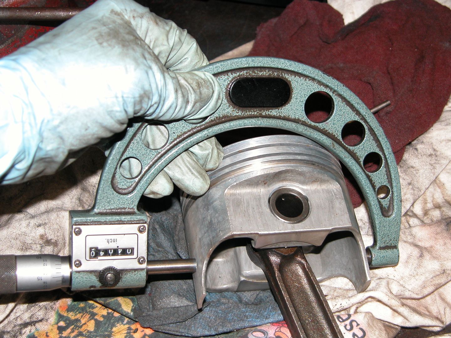
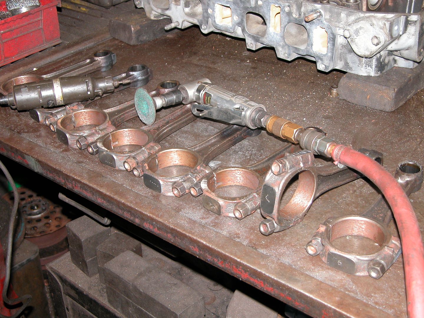
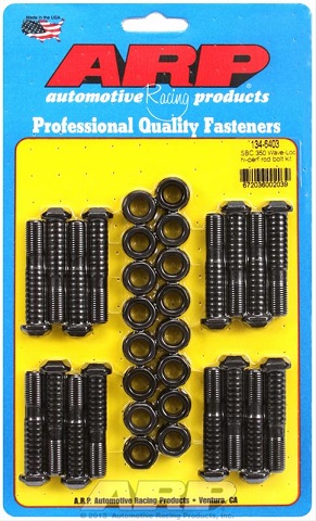
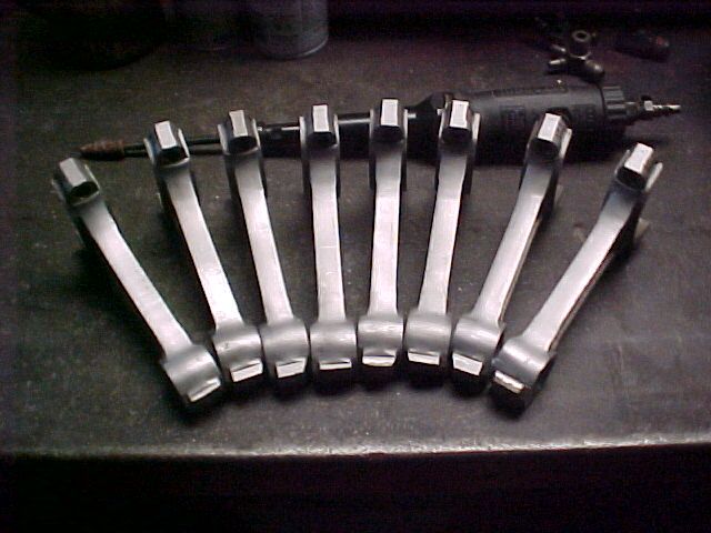
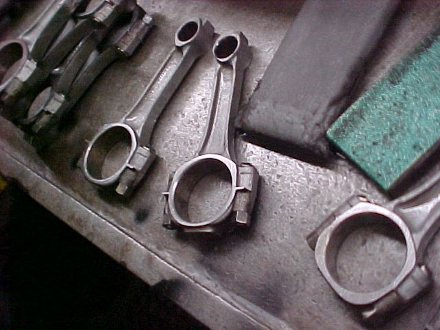
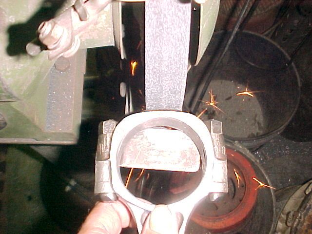
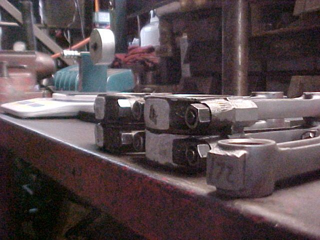
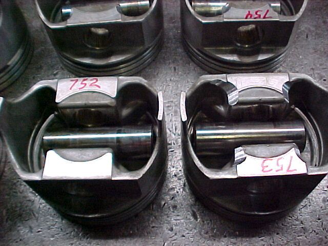
I know from long experience that the stock connecting rods that are pictured above are fully adequate for a stock rebuild ,but I would never personally re-use stock connecting rods without upgrading the rods with a careful polish resizing, shot peening, and bead blast, then,upgrading to ARP wave-lock rod bolts, but that is fairly expensive in most guys eyes, and in my mind the re-use of stock rods with pressed in pins,is a total waste of time, as 
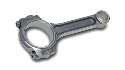
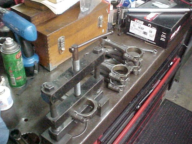
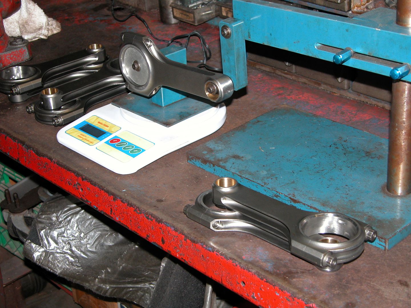
I vastly prefer far stronger 7/16" ARP rod bolt SCAT rods with the full floating pistons,pins and 4340 forged rods that allow easy self assembly and reassembly during the often repeated clearance checking procedures.
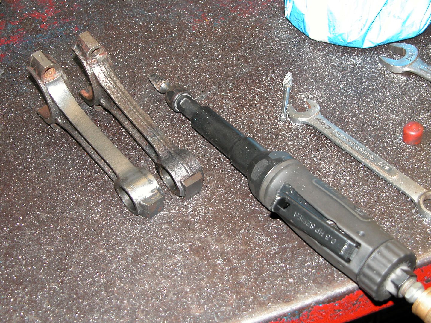
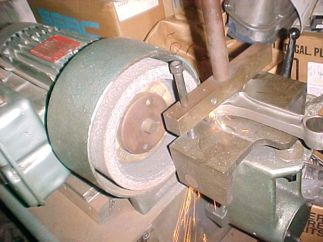
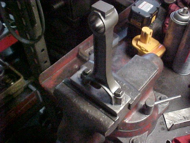
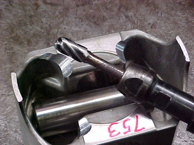
Polishing the side beams,connecting rods and removing the surface roughness, helps prevent crack formation, from surface irregularity's and stress concentrating flaws in the surface,

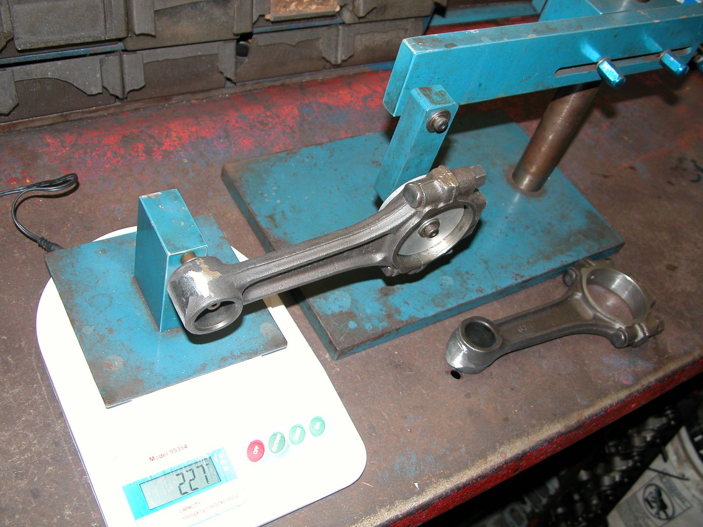
the reason is simple, by the time you pay to have the much stronger ARP rod bolts installed on stock rods and have them polished to remove stress risers the average machine shop parts and labor cost equals or exceeds the cost of the far stronger SCAT aftermarket rods, yes they may require you rebalancing the rotating assembly to use them, but so will adding new pistons to old rods, or even polishing old rods in a few cases.

http://www.superchevy.com/how-to/74038- ... ting-rods/

http://www.fordmuscle.com/archives/2007/12/400Rods/

http://www.hotrod.com/how-to/engine/cho ... ting-rods/

http://scatcrankshafts.com/


CHEVY FORGED 4340 I-BEAM
With ARP 8740 7/16" CAP SCREWS
CHEVY SMALL BLOCK I-BEAM RODS with 7/16" CAP SCREW BOLTS

Part No Short No Description Rod Length Crank Pin Wrist Pin B.E. Width Weight
2-ICR5700-7/16 25700716 BUSHED 5.700" 2.100" .927" .940" 590
2-ICR6000-7/16 26000716 BUSHED 6.000" 2.100' .927" .940" 605
2-ICR6000-2000-7/16 26001716 BUSHED 6.000" 2.000' .927" .940" 605
2-ICR6125-7/16 26125716 BUSHED 6.125" 2.100" .927" .940" 610
2-ICR6125-2000-7/16 26126716 BUSHED 6.125" 2.000" .927" .940" 610
2-ICR6200-7/16 26200716 BUSHED 6.200" 2.100" .927" .940" 620
ARP 8740 7/16" CAP SCREWS
2-ICR5700-7/16A 25700716A BUSHED 5.700" 2.100" .927" .940" 590
2-ICR6000-7/16A 26000716A BUSHED 6.000" 2.100' .927" .940" 605
2-ICR6000-2000-7/16A 26001716A BUSHED 6.000" 2.000' .927" .940" 605
2-ICR6125-7/16A 26125716A BUSHED 6.125" 2.100" .927" .940" 610
2-ICR6125-2000-7/16A 26126716A BUSHED 6.125" 2.000" .927" .940" 610
2-ICR6200-7/16A 26200716A BUSHED 6.200" 2.100" .927" .940" 620
ARP 2000 7/16" CAP SCREWS
CHEVY BIG BLOCK I-BEAM RODS with 7/16" CAP SCREW BOLTS
Part No Short No Description Rod Length Crank Pin Wrist Pin B.E. Width Weight
2-ICR6135-7/16 26135716 BUSHED 6.135" 2.200" .990" .992" 780
2-ICR6385-7/16 26385716 BUSHED 6.385" 2.200" .990" .992" 785
2-ICR6700-7/16 26700716 BUSHED 6.700" 2.200" .990" .992" 810
ARP 8740 7/16" CAP SCREWS
2-ICR6135-7/16A 26135716A BUSHED 6.135" 2.200" .990" .992" 780
2-ICR6385-7/16A 26385716A BUSHED 6.385" 2.200" .990" .992" 785
2-ICR6700-7/16A 26700716A BUSHED 6.700" 2.200" .990" .992" 810
ARP 2000 7/16" CAP SCREWS
CHEVY LS-1 I-BEAM RODS with 7/16" CAP SCREW BOLTS
Part No Short No Description Rod Length Crank Pin Wrist Pin B.E. Width Weight
2-ICR6100-927 26100927 BUSHED 6.100" 2.100" .927" .940" 595
2-ICR6100-944P 26100944P PRESSED 6.100" 2.100" .944" .940" 600
ARP 8740 7/16" CAP SCREWS
2-ICR6100-927A 26100927A BUSHED 6.100" 2.100" .927" .940" 595
2-ICR6100-944PA 26100944PA PRESSED 6.100" 2.100" .944" .940" 600
ARP 2000 7/16" CAP SCREWS
yes much of that labor could be done at home if you have the correct tools and know whats required,
http://www.summitracing.com/parts/arp-134-6403
arp-134-6403.jpg


sca-25700_w.jpg

http://www.summitracing.com/parts/sca-2 ... /overview/

YES READING LINKS AND SUB LINKS HELPS A GREAT DEAL HERE

viewtopic.php?f=53&t=1168&p=29973&hilit=polish+rods#p29973

viewtopic.php?f=53&t=6909&p=22571&hilit=floating+pins#p22571

viewtopic.php?f=53&t=978&p=1711&hilit=floating+pins#p1711
 
I agree with you Grumpy and if I was building the 350 with a budget of any type and really wanted a 350 I would buy some parts that will not be purchased for this engine. My original plan was to just drop in the complete used 350 and use it if it ran. Then my buds at the machine shop convinced me to build this one instead with parts I had kicking around and leftover used parts they had at the shop in exchange for the complete used engine and another set of heads I had. The deal was no out of pocket money from me for any parts or services. All disposable income car money I have get to go to the Firebird project until its done. If I was spending money to build up an engine for the Malibu it would probably be a big block.

This engine project is as much a learning project for me as it is because I wanted to ditch the V6. I drove the car for many years as a DD with the 6.


With the rods marked and disassembled it's time to start working on them. In this first step I'm using a carbide bit to grind away the ridge in the center of the side and blending into both ends. Care needs to be taken to keep rods even when viewing the sides not being ground and also not to remove too much material. The square "chunk" of metal at the top of the rod is left alone and will be ground a couple steps from now when I "balance" the rods. The bit in the tool is used for steel, the one on the bench for aluminum. The last person who used the air tool before me had been doing some welding repair work on aluminum heads.

018.jpg
 
After grinding the sides of the rods with the carbide bit, a sandpaper roll on a tapered bit in an air tool is used to smooth the grinding marks and then the rods are glass beaded. After that they're oiled down so they won't rust. It's not really oil, but a concoction based on tranny fluid. Pic below taken after glass beading and they don't look as polished as they do before blasting. Picture quality is lower now because my good camera decided to commit suicide and jumped off a chair onto concrete damaging itself beyond use. Hopefully it's repairable but until then the old camera is back in service.

MVC-027F.jpg
 
Quote Originally Posted by COPO-RAT View Post
What is the purpose of grinding the ridge off the rods?
Polishing the beams helps prevent crack formation. Generally followed by shot peening the rods to restore compressive surface stresses, which extends fatigue life

Do do all GM rods have that ridge? Check mine out. They have a recess instead of a ridge, does that mean they aren't GM? Sorry if I'm hijacking the thread, it is not my intention, I'm following this and getting some good info.

No hijack worries! Glad the threads usefull! I have a really tough time with pics on my current computer setup but it looks like your rods have the ridge. It's wider and not as pronounced, looks like it's 1/4-3/8 wide by the wrist pin and almost as wide as the side of the rod on the beam.. Looks like a GM rod to me, just a newer casting. Mine are early 70's.

Greg was correct about the shot peening however we don't have a machine at the shop so glass beading was the next best thing available. Most modern performance builds get fancy rods but there's no budget for that on this build.

I started "reconditioning" the rods. First step is to make sure there's no burrs on the sides of the big end or where the caps meet the rod by running a flat file over them. Then the rod gets clamped into a machine that grinds a few thousandths off of the flat surface where the caps meet the rod. Then the caps are also ground flat on the surface that meets the rod. Here's a pic of one of the rods being ground. The rotating stone wheel is stationary and the rod is moved past the wheel while clamped square to the wheel in an arm thats moved by hand. I couldn't hold the camera far enough away while operating the machine to get the whole machine in the pic.

MVC-018F-1.jpg
 
I cleaned up the rod bolts on a wire wheel. Next step is to reinstall the bolts for the caps. They are an interference fit so they need to be pounded into place. We have an aluminum block that gets mounted into a vice which has holes for the bolts to slide into. Then the bolts are installed with a 2 lb hammer and a large drift.

MVC-018F-2.jpg


Once all the bolts are installed the caps that correspond with each rod are installed. The nuts for the caps need to be torqued to 45 lb. ft. so a special rod vice is used to hold them. The rod vice has wide machined flat clamping surfaces so no damage will be done to the rods working on them.

MVC-019F-1.jpg
 
Once all the caps are torqued the sides of the rods where the bearings fit in are block sanded with a coarse and then fine paper to remove any small burrs that have formed where the mating surfaces were ground and make sure the sides are nice and flatwhere the caps meet the rods. Then the rods are blown off and cleaned to remove any particles.

MVC-040F.jpg


Once the rods are clean it's on to the honing operation! Since the mating surfaces of the rod and cap have been ground the hole for the bearing is now smaller than stock. This allows us to hone the bearing contact surface while opening up the hole to the correct diameter while being sure the enlarged hole is perfectly round.

Usually specs are checked (in a book) to determine the correct diameter of the hole needed for the rod bearings and then the gauge on the right side below is set with a micrometer. Because this is a commonly used size we have a SBC connecting rod we know is at "0" to calibrate the gauge instead of using a micrometer, just saves setup time. The hole will be made to stock size and the bearings will be ordered to make up the difference needed if the crank is turned down.

The size of the hole is checked on the gauge in the pic below where the rod is hanging. The hole is honed by stones spinning on a shaft while oil drips on them. The bar on the left holding up the horizontal rod keeps the rod stable while it is slid in and out (by hand) on the spinning shaft with the stones. Technique is required to get an even finish and desired crosshatch. In this case I'm opening the holes up until they are still a thousandth undersize and will take out the last thousandth after balancing and when the rods are cool so the measurements will be precise.

MVC-041F.jpg
 
great post and really information heavy pictures that many of the sites members have probably not seen before!
 
grumpyvette said:
great post and really information heavy pictures that many of the sites members have probably not seen before!


Thanks Grump!

Time to "balance" the rods! This is done after honing because the weight of the big end of the rods may have changed depending on how much material was removed grinding the mating surfaces and then honing the end.

Each end of the rod is weighed using a digital scale and the balancing apparatus shown below. An adapter that closely matches the diameter of the big end is used on either the stationary pivot or the floating pivot on the scale depending on which end you're weighing. The weight of each end is marked on every rod.

Starting with the heaviest "big end" rod the square chunk of metal on the end of the rod is ground down on the rods that are heavier than the lightest one. After they were all down to the weight of lightest one I examined to see if they could all be lightened a bit more without sacrificing durability and took a couple more grams off of each one. The same procedure was then performed on the small end of the rods.

They're now all at 414 and 169 grams. Not super light "race weight" but now they're lighter and equal weights. Less weight allows the engine to "rev" more quickly. Do I really need polished balanced rods for this engine? Probably not, really. LOL But it's cooool!~ AHAHAHA And I have a full shop at my disposal, so why not? As with anything, different customer requests, applications, and products may use different procedures so YMMV.

It was about 3 AM when I was doing this and I forgot to take lots of pics, so the first 2 showing the equipment used are pics I had from other peoples projects lready completed and the second 2 are my rods.

006-1.jpg


002-1.jpg


MVC-042F.jpg


MVC-044F.jpg
 
COPO-RAT said:
I've been waiting to see this step.........unfortunately for me I was incorrect in thinking that the 'balancing' was something I was going to be able to do myself......guess that's what I get for thinking!
In your second balancing pic, it appears that the square chunk at the small end of the rod has been completely ground off, why couldn't you have taken yours completely off?

You could certainly rig up a makeshift balancing apparatus. If you can borrow a postal scale from your local drug dealer I don't see any reason it wouldn't be just as accurate. The advantage to the equipment is just that it's quick to set up, heavy so it remains stable, and self centers the rod large rod end. Since you just want to balance your one set you could pretty much duplicate the mechanism with a couple pieces of wood and a couple nails. Maybe a coat hanger to give it a MacGyver touch. It would take a little more time to use your makeshift setup each time you measured the weight of the rod as you're grinding but it would probably be really really close to the same as using the machine shop apparatus. I will try making one and report back here whether it can be done and how accurate it is compared with the fancy setup.

The stock rods are often off as much as 10 grams on the big ends and 7-8 on the small end of stock GM rods from the various divisions so if you can bring those within a gram yourself at home I say go for it!

As for the rod in the second pic; Sometimes due to casting inconsistancies the lighest rod end that you're trying to bring the others down to still has a part of the square chunk left even though the entire chunk has to be removed from one of the other rods to get down to the weight of the lightest one. Thats part of the reason for bringing them all down to the weight of the lightest one first before deciding whether you can lighten them all a little more. Once they're all down to the weight of the lightest one there may not be enough "meat" left on one of the ends to easily remove more metal. One of my rods has very little of the square left on the small end and one doesn't have any of the square on the big end (different rods).There are also other techniques to remove a bit more weight such as using a grinding cookie on an air tool (more time involved) but for my engine it certainly isn't necessary. The rod in that 2nd pic was the one in the set that had the most metal removed. The fancy rods in the first pic went into a nice 406 SBC I put in a mud truck last weekend.

pic below: Mud truck with stock wheels on so it would be low enough to get the engine in(It's on the ground!). It's getting 52" mudders!!! Whoever took the engine and tranny out didn't mark the wires so I've got some sorting to do! Getting rid of all the computer stuff for the throttle body engine and just running an MSD setup with a carb. Owner in pic the day on a 6' ladder the day we put the trans in.

MVC-015F-2.jpg


MVC-018F.jpg
 
COPO-RAT said:
I was unaware that each end of the rod was balanced individually, which that in itself confuses me. How can you be measuring the weight of one end if the other end is being supported by something? Does the rod have to be completely level (the beam part) while measuring each end? Or does it not matter as long as the angle the rod is at is consistent with every rod you measure? I have some friends that could easily turn a piece of delrin (or aluminum or whatever) to use as a bushing in the big end of the rod and I think it would be easy enough to build some sort of fixture to support the rods during the weighing, but as stated before, I don't know/understand how the rod needs to be positioned while doing the weighing.

Should be roughly horizontal which is one of the adjustments on the stationary part of the manufactured equipment. I think it'd still be pretty accurate if the rod was tilted, just all of the measured weights would be skewed one way or the other equally a little bit)
 
Had a few minutes last night after decking blocks so I got my pistons out and weighed them for balancing. They ranged from just under 752 to 754 grams (with corresponding wrist pins). Tonight I ground away some material by the wrist pins on the heavier ones to bring them down to 752. I could have milled the inside of the top of the piston to remove the weight but for this engine the extra time and effort required isn't worth it.

MVC-032F.jpg


MVC-034F.jpg
 
Along with the engine building I'm working on a few other things for the car. So this post is interior work.

After 30 years the package shelf like many other original ones in G bodies looked really bad. It had warped, been repainted with vinyl dye, faded, had speaker holes for 6 X 9's hacked, couple different sets of speakers with different mounting bolt patterns and looked bad. The dark window tint kept it out of plain sight for the most part. Then Ralph the "expert" roll cage installer put another hole in it finishing it off. So I decided to make a new one.

A while back I picked up a sheet of white hardboard at Home Cheapo for 6-7 bucks or something like that. traced out the old rear shelf and cut the hardboard with a skillsaw.

MVC-018F.jpg


Since I don't have any extra loot to spend on the car right now I've been keeping my eyes open for some black rug raterial to work with for the shelf. A couple nights ago There was a black sub box out for junk at the repair garage next to the machine shop so I gave it a quick look in the dark and took it home to examine in daylight.

MVC-026F-1.jpg


In daylight it looked like there would be enough usable material if I could peel it off. It must have been part of a "Custom" 80's-90's install complete with sheetrock screws and fiberglassed to the floorpan!

MVC-031F.jpg


So I chiseled the material off with a painters scraping tool and razor blade. Turned out to be enough material as long as I put a slice (not by me) over a speaker hole.

MVC-035F.jpg


MVC-024F.jpg


Cut the material out and made small version of the speaker holes for referance. Then figured out where I want the speaker covers. I'm using an old set of covers for a retro backdated appearance that will be mounted to the package shelf with the speakers mounted by themselves. I've spent enough time screwing around with shelf 6 X 9's to learn my lesson and am eliminating the sandwich mounting where the bolts that hold the speakers also hold the covers. Next I need to find my glue, some fasteners for the speaker covers and make a vinyl rollover for where the shelf meets the backseat.


MVC-025F-1.jpg


MVC-027F-1.jpg
 
Back
Top