no one I know can remember everything about every year corvette, thats why we usually buy shop service manuals,when we buy a older corvette.
(personally ID look that PROCEDURE up in my CORVETTES FACTORY SHOP MANUAL, if I had that option,
(YOU SHOULD OWN a FACTORY SHOP MANUAL)
HERES WHERE YOU PURCHASE ONE, and ID suggest buying a trouble code reader/scanner and a multi meter also
http://www.helminc.com/helm/product2.as ... itemtype=B
because off the top of my head, I don,t remember if that year even uses a reprogrammable control,or a replaceable chip, or whats required. but this info below may help
http://www.corvettephotographs.com/c4vettes/ecm.htm
Recovering the C4 ECM/PCM Codes
The following applies to recovering the OBD-I (On Board Diagnostics) codes on the 1984 through 1993 model C4 Corvettes via the 12 pin ALDL connector located under the dash just to the right of the steering column.
1994 and 1995 C4s also had the OBD-I system but used a 16 pin access connector that would become standard for the OBD-II system used on 1996 and later Corvettes. For 1994 and later models, you will need to recover the codes using a special procedure involving the speedometer and the odometer as explained in the service manual or use a special diagnostic device known as a scan tool.
On Board Diagnostics
The 1984 through 1996 Corvette has an On Board Diagnostic (OBD) system which is part of the Electronic Control Module or ECM, (also known as Powertrain Control Module or PCM in 1994 and later Corvettes), plus a system of sensors located throughout the automobile. The ECM/PCM gathers input from the sensors and continuously changes the fuel/air mixture, timing and other engine and transmission parameters so as to optimize the operation of the automobile for the best compromise between performance, efficiency and exhaust emissions.
Any time a sensor's output exceeds a Hi/Lo reference parameter stored in a Programmable Read Only Memory (PROM) array in the ECM/PCM module, an error code is set and retained in the ECM/PCM memory.
This event causes the lighting of the Malfunction Indicator Lamp (MIL) on the "tell tale" panel (more commonly known as the "Check Engine" light) or the SYS (System) lamp located on the instrument panel above the speedometer on later C4 automobiles .
If the problem clears and remains cleared for 10 seconds, the light will extinguish however, the error code is still stored in the ECM/PCM memory.
Regardless of whether the problem is constant or intermittent, the error code can be recovered through a user friendly system involving the MIL (Check Engine) or SYS lamp.
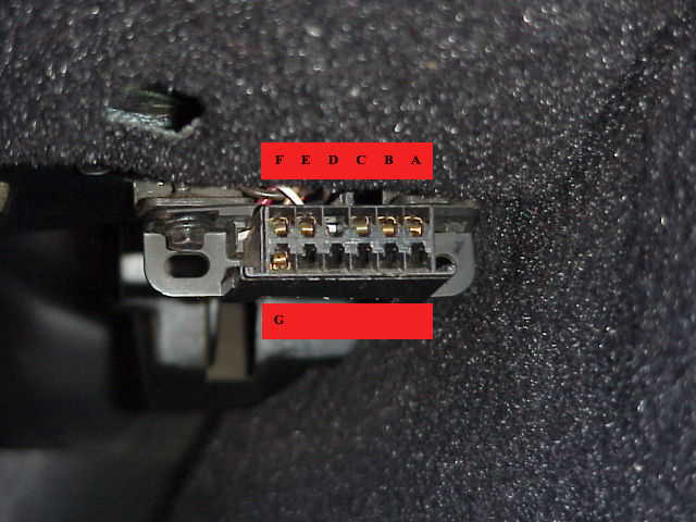
To the immediate right of the steering column under the dash, you will find a multiple pin electrical connector. This connector is called the Assembly Line Data Link (ALDL).
From 1984 until the end of the 1993 model year a 12 pin ALDL was used. After that, a 16 pin ALDL connector was used. The 1994 and 1995 model year still used the OBD-I system even though they have 16 pin connectors. The 16 pin connector in the 1996 C4 is used for the much more complex OBD-II system and a scan tool is required to discover the OBD-II system's secrets.
The early ALDL connector has room for 12 pins however only 7 are populated and of those we are only interested in Pin "A" and "B" for this procedure.
Remove the ALDL cover (in the unlikely event that there still is one in the automobile...they usually were lost early in the automobile's lifetime) and as you view the pins, you will find the top row fully populated whereas not all are populated pin on the bottom row.
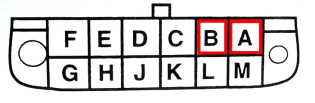
On the top row (as you view the connector from the cockpit), the pin designators are F,E,D,C,B,A.
Here is a typical 12 pin connector. (Some have more pins on the lower row than this example).
The pins you are interested in are those two pins in the top, right hand portion of the connector, designated pins "A" and "B".
Pin "B" is the diagnostic enable pin and pin "A" is ground. By grounding pin "B", you enable the diagnostic readout functionality of the ECM/PCM.
Recovering Trouble Codes
To recover the codes, it is necessary that you short pins "A" and "B" together using a small section of electrical wire. Alternatively, you can cut up a paper clip and fashion it into a shorting device.
Regardless of your method, you will want to utilize something that will reliably make contact with the two pins but will not damage the connector or the pins.
With the ignition turned Off, short pins "A" and "B" on the ALDL using your previously prepared pin shorting device.
Turn on the ignition but Do Not start the automobile.
Within a few seconds, your "Check Engine" light (early C4s) or "SYS" light (later C4s) will flash a code of 12. There will be a single flash followed by two flashes and this will repeat three times: Flash (pause) Flash Flash (long pause), Flash (pause) Flash Flash (long pause), Flash (pause) Flash Flash (long pause).
Code 12 is a delimiter or marker code to show where the error code string begins and ends.
After the three code 12 flashes, you will either get an error code (or codes) or you will get another string of code 12 flashes if there are no trouble codes stored.
All codes are repeated three times with a long pause between each code group so (for instance) you could recover a string like this: 12, 12, 12, 36, 36, 36, 44, 44, 44, 12, 12, 12.
In this example, your OBD has stored error codes indicating that the Mass Air Flow burn off circuit has exceed the Hi/Lo limits (Code 36) and that the Exhaust is to lean (Code 44).
Whether or not this means that the sensor is bad or that the parameter it measures has truly been exceeded is yet to be determined however, you do know that the PROM based limits for these two sensors have been exceeded.
If the "Check Engine/System" light is on when the engine is running (during normal, driving operation in other words), the condition(s) are currently present; if the light is not on during normal operation, the limits were exceeded at some point in time and the event was recorded in memory but the reading has since returned to the normal operating range.
Once you have determine the error code situation, you can set about troubleshooting the problem or you can take your vehicle to a Corvette repair shop, tell the technician what you have found in the OBD system and perhaps somewhat shorten the repair time.
Remember to remove the shorting device from the connector after you have read the codes.
Clearing the Codes
To clear the codes from memory, remove the negative battery cable for a minimum of 10 seconds.
Very Important: Make absolutely certain the ignition key is turned to the off position. You run the very real risk of destroying the ECM/PCM module if you connect the battery with the ignition switch turned on.
Disconnecting the battery will clear all stored codes but it will also clear the radio button presets, clock, trip odometer, average gas mileage memory, power seat memory (if you have that option) and anything else that stores something in memory. Your ECM/PCM computer will also have to relearn your driving habits again and adjust the timing/mixture/exhaust emissions to your driving style.
Troubleshooting using the ECM Codes
The central point to keep in mind when troubleshooting the codes is there is no reason to automatically believe a sensor has failed. It is possible that a sensor itself is exhibiting a hard or a intermittent failure but it is more likely that a connector has gotten dirty, a wire has broken or some underlying problem is present and the sensor has done it's job.
For instance, a Mass Air Flow (MAF) error code is often a dirty connector at the MAF sensor as opposed to a bad sensor. Similarly, a code indicating a lean condition can be timing, fuel delivery or dirty/plugged injectors. The codes are normally a symptom, not the disease.
Do not immediately buy a new sensor in hopes that will fix the problem. Look into the problem a bit more first using the links from the code table as your guide and consider buying a scan tool so you can determine exactly what your ECM/PCM is being told by the various sensors and---just as important---how it is reacting to the sensor inputs.
The table which follows lists the error (trouble) codes which can be stored and recovered using the pin A/B technique explained above. To learn some possible causes for the codes, click on the code number.
ECM Codes
Code
Circuit or Sensor
13 Oxygen Sensor Circuit
14 Coolant Sensor Circuit (High)
15 Coolant Sensor Circuit (Low)
16 Ignition Pblms (Used on 1992-1996 models only)
21 Throttle Position Sensor (TPS) (High)
22 Throttle Position Sensor (TPS) (Low)
23 Intake Air Temperature (Low)
24 Vehicle Speed Sensor (VSS)
25 Intake Air Temperature (High)
26 Quad Driver Module Number 1
27 Quad Driver Module Number 2
28 Quad Driver Module Number 3
32 Exhaust Gas Recirculation Circuit
33 Mass Air Flow Sensor Circuit (1985-1990)
33 Manifold Absolute Pressure High (1984)
34 Mass Air Flow Circuit (1985-1990)
34 Manifold Absolute Pressure Low (1984)
35 Idle Air Control Circuit (IAC)
36 Mass Air Flow Burn Off Circuit
41 Cylinder Select Error Circuit (1985-1991)
42 Electronic Spark Timing Circuit (EST)
43 Knock Sensor Circuit
44 Lean Exhaust Present
45 Rich Exhaust Present
46 VATS Anti Theft Circuit Fault
51 PROM/EEPROM Error
52 Oil Temperature Circuit (Low Temperature)
53 System Charging Voltage High or Low
54 Fuel Pump Circuit (Low Voltage)
55 Engine Running Lean
62 Oil Temperature Circuit (High Temperature)
63 Oxygen Sensor Circuit (Open)
64 Oxygen Sensor Circuit (Lean Exhaust)
65 Oxygen Sensor Circuit (Rich Exhaust)
66 Air Conditioner Pressure Limit Exceeded
67 Air Conditioner Pressure Limit Exceeded
68 Air Conditioner Relay Fault
69 Air Conditioner Clutch Fault
72 Gear Selector Switch Fault (Start Lockout)
Possible Failures Associated with ECM Codes
Code
Possible Fault (From most likely to least likely)
13 Check wiring and connectors. Bad Sensor
14 Check wiring, connectors, thermostat. Monitor actual engine temperature. If within limits, and wiring/connector is OK, change thermostat and/or sensor.
15 See above, particularly thermostat
16 Direct Ignition (DI) Fault
21 Sticking or Misadjusted TPS. Also check wiring/connectors. Adjust/replace TPS.
22 Sticking or Misadjusted TPS. Also check wiring/connectors. Adjust/Replace TPS.
23 Measure sensor resistance with Digital Ohm meter. Must not be 0 ohms or infinite ohms. Replace if it shows one of these readings. Check wiring/connector of sensor. If OK, replace sensor.
24 Only valid if vehicle moving. Check connections at ECM Check TPS setting. Possible ECM failure.
25 Measure sensor resistance with Digital Ohm meter. Must not be 0 ohms or infinite ohms. Replace if it shows one of these readings. Check wiring.connector of sensor OK.
26 Check EGR, Canister Purge and AIR pump relays with a digital Ohm meter. A resistance of less than 18 ohms indicates a bad relay. If OK, potential ECM failure.
27 Potential ECM or on a manual transmission car, potential upshift relay problem. Check relay, replace if less than 18 Ohms using a digital Ohm Meter.
28 Air conditioning Clutch relay and/or cooling fan relays. Check with digital Ohm meter, replace if less than 18 Ohms. If relays OK, potential ECM failure.
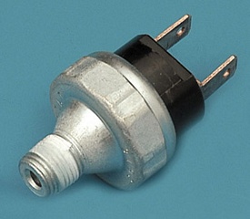
32 The most common cause of this code is a bad or intermittent EGR switch which is located on the EGR pipe between the exhaust manifold and the intake manifold. Replace this switch first when you get this code. Next, check electrical connections at EGR valve solenoid and then the ECM. Check all vacuum lines for leaks especially around the EGR valve. Possible ECM failure.
33 (1985-1990) Inspect intake system for leaks, Inspect for vacuum leaks, Check MAF connector and wiring, Check MAF for open using digital Ohm meter. Possible ECM failure.
33 (1984) Check vacuum hoses. Check wiring to sensor. Change sensor. Check connections at ECM.
34 (1985-1990) Clean the throttle body. Check MAF connections. Replace MAF relay. Replace MAF Sensor. Possible ECM failure.
34 (1984) Check Vacuum hoses associated with MAP sensor. Check wiring and connections, particularly at ECM. Replace the sensor. Possible ECM failure.
35 Check fuel pressure, injectors, leaking throttle body. Change the IAC valve.
36 Check connections at MAF, MAF relay and MAF Burn off relay. Check resistance of MAF relay and MAF burnoff relay with digital Ohm meter. replace if less than 18 Ohms. Possible ECM failure.
41 Check wiring at ECM. Possible PROM failure, or incorrectly seated PROM. Reseat PROM. Possible ECM failure.
42 Check wiring at ignition module. Replace ignition module. Possible ECM failure.
43 Check ECM wiring. Replace knock sensor
44 Check wiring.connectors at Oxygen sensor. Check fuel pressure. Replace Oxygen sensor.
45 Check evaporative charcoal canister for smell of fuel (which normally comes from filling fuel tank to full). check fuel pressure regulator. Possible leaking fuel injector or sticking/bad EGR valve. Possible bad Oxygen sensor.
46 With negative battery lead disconnected and using high pressure, non residue contact spray cleaner, spray into area where ignition key inserts followed by inserting and removing key several times. Check for open/short on harness from steering column VATS ignition key to ECM. Possible defective anti-theft module.
51 Faulty or incorrect PROM in the ECM. Change PROM with correct version for automobile.
52 Check connections at the oil temperature switch. If OK, replace switch.
53 If voltage is more than 17.1 or less than 10 volts, this code will be set. Check battery leads, alternator drive belt for tightness and have electrical shop check alternator output. Voltage with engine off should be 12 volts. Voltage with engine running should be 14-15 volts. Use digital volt meter for checks and measure at the battery terminals.
54 Using digital Ohm meter, check fuel pump circuits for shorts or opens.
55 This code is set when there is not enough fuel when accelerating. A possible fuel pump failure or insufficient fuel pressure due to a fuel line restriction is indicated.
62 Check wiring associated with Oil temperature switch. Replace switch.
63 Check wiring and connections to Oxygen sensor.
64 Check wiring and connections from Oxygen sensor to ECM. Check ECM ground terminal and battery ground. Check fuel pressure and fuel pump. Replace Oxygen sensor if all of above OK.
65 Check evaporative charcoal canister for fuel fumes. Replace if contaminated. Check oil for presence of fuel. Check fuel pressure regulator, fuel pump, check for leaking injectors, Check for stuck/defective EGR valve, Replace Oxygen sensor if all above OK.
The C4 Corvette uses several computers---more in the later models than the early years--- and each has it's own set of trouble codes. The Anti-Lock Brake System (ABS) , Automatic Slip Regulation (ASR), Selective Ride System (SRS) as well as the Air Conditioner Controller, the Air Bag's computer system (called the DERM module) plus the Central Control Module (CCM) on 1990 and later C4s, all have their own computers and their own set of possible trouble codes. Some can be recovered without a scan tool, some cannot. You will need a service manual for your year C4 to discover the procedure to gain access to those codes.
http://www.corvettephotographs.com/c4vettes/codes.htm
C4 Corvette Diagnostic Code Recovery Techniques
In the 'In Depth' section of this site, the ECM (Engine Control Module) codes are listed and the technique for recovering those codes on the 1984 through 1993 model Corvette is explained.
This fact sheet reviews that information and also shows you how to recover ECM codes for the rest of the C4 models plus shows how to recover the ABS, ASR, SRC, DERM and RTD codes as well.
Code Recovery: 1984 through 1993:
To recover ECM codes from the 1984 through 1993 Corvette, place a short as shown below between pins "A" and "B" on the ALDL (Assembly Line Diagnostic Link) connector. This connector is located under the dash just to the right of the steering column and has space for 12 pins although not all of the cavities will be populated.
.
Turn the ignition switch to "On" but do not start the engine.
Depending on the model year, either the "Check Engine Light" or the "Service Engine Soon" will begin to flash.
As the code display sequence begins, you will see a flash followed by a pause and then two flashes. This is the indication for the number "12". The number 12 is a delimiter intended to show where the ECM code display starts and stops.
Code 12 will flash three times and then any stored codes will flash. When all codes have been displayed or if there are no stored codes, the number 12 will again flash three times.
For example, a problem with the EGR system (code 32) will be shown as 12, 12, 12, 32, 32, 32, 12, 12, 12.
This would be displayed on the Check Engine/Service Engine Soon light like this:
12: flash (pause), flash, flash, (long pause)
12: flash (pause), flash, flash, (long pause)
12: flash (pause), flash, flash, (long pause)
32: flash, flash, flash (pause) flash, flash (long pause)
32: flash, flash, flash (pause), flash, flash (long pause)
32: flash, flash, flash (pause), flash, flash (long pause)
12: flash (pause), flash, flash, (long pause)
12: flash (pause), flash, flash, (long pause)
12: flash (pause), flash, flash (long pause)
The ECM code display will repeat until you turn off the ignition switch and remove the short.
Additional Codes available on the 1984 through 1993 Corvettes:
Selective Ride Codes:
On the 1989 Corvette, if you have the Selective Ride Option, any codes associated with the SRC will cause the Service Selective Ride System light to flash when you short ALDL pins "A" to "B". The sequence uses the same 12, 12, 12 delimiter as the ECM code display uses.
Some later Corvettes require you to short pins "C" to "A" to flash codes on the SSR light. It varies with the model and you will need to consult the service manual for your particular model year to find out if these are the proper pins or if there is another technique requried.
ABS Codes:
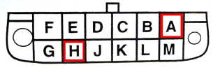
On the 1990 and 1991 model shorting pin "H" to pin "A" will cause the ABS light to flash ABS codes. (Beginning in 1992, there is another technique which is explained below).
Not all codes are displayed using this technique. There are four codes that will not display without a scan tool. Also, note that the 1986 through 1989 Corvettes will not display any ABS codes. A special test fixture is required for those models.
Sequenced Code Recovery - 1990 through 1993:
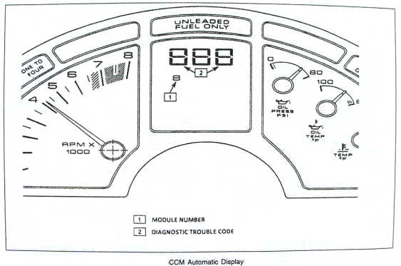
With the interior redesign in 1990, Chevrolet added additional computer capability. The CCM (Central Control Module) was added and a method was provided to display codes on the speedometer of the Corvette.
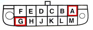
From 1990 through 1993, you shorted ALDL pin "G" to "A" and turned the ignition to "On" without starting the engine.
This action will cause the speedometer and trip odometer to become a troubleshooting aid:
The codes will display on the speedometer. If there are no codes, the speedometer will show three dashes (---) and if the CCM cannot communicate with the other computers, the letters "ERR" will show up on the display.
The module number associated with the codes will be displayed on the odometer and will show which computer's codes is being displayed.
For the 1990 and 1991 Corvette, the modules are Module "1", the CCM computer and module "4", the ECM module.
For 1992 and 1993, an additional module, module "7", the ABS (Anti-Lock Brake System) and ASR (Automatic Slip Regulation System) codes will be displayed.
The codes will show up for three seconds each and once all codes have been displayed, the speedometer will show three dashes. You can either turn the ignition off for five seconds and then back on to repeat the process or turn the ignition off and remove the short to restore normal operation.
Sequenced Code Recovery - 1994 through 1996:
In 1994, Chevrolet went to a 16 pin ALDL connector in preparation for the federally mandated change to the much more capable OBD-II (On Board Diagnostics - Version 2) system.
As with the 1990-1993 model, you can display codes on the speedometer but the pins to be shorted are different:
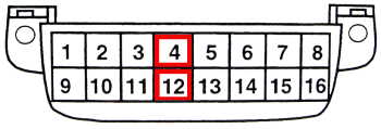
Beginning in 1994, you short pin "12" to pin "4" and once again turn the ignition switch to "On" without starting the engine.
The speedometer will display any codes using the same protocol as the 1990-1993 model but there are some changes in the designation for the modules plus additional modules are added:
Module "1" is still the CCM module.
Module "4" is now called the PCM module (Powertrain Control Module) because automatic transmission computer control was added to Engine Control Module in 1994.
Module 7 (on the 1996 model only) is the RTD module. (This is the Real Time Dampening module which replaced the Selective Ride Control module in 1996).
Module 9 is the ABS/ASR module number from 1994 through 1996.
Finally, Module "A", the DERM (Dynamic Energy Control Module --- the air bag control module) will be requested to show any codes.
Just like the 1990-1993 display, you read the codes on the speedometer and read the module number on the trip odometer.
Again, you can cause the codes to repeat by turning the ignition off for five seconds and then back on.
Turn the ignition off and remove the short to restore normal operation.