https://www.enginebuildermag.com/2021/03/induction-system-science/
The complexity of cylinder head set up and flow bench testing comes in the form of math, aerodynamics, thermodynamics, and the physics it takes to design the correct port and manifold design for a particular engine combination. These processes take years to master.

By
Greg Jones
on
Mar 26, 2021
Understanding Airspeed & Airflow
For years now, many folks in the industry have become solely fixated on cubic feet per minute (cfm) numbers when it comes to the performance of cylinder heads. This fixation places importance on a number that is easily manipulated, while ignoring other data about a cylinder head’s performance. This singular thinking is wrong and won’t do you any favors come race day if you ignore all the other aspects that help the induction system deliver performance.

Ported Brodix heads. Photo from CT Performance.
Experienced cylinder head designers and head porters often tell people not to pay attention to flow numbers, but that does not mean that flow numbers don’t matter. This distinction is often lost in translation. Flow numbers are important, and they do have meaning – just not the meaning most people attribute. Airflow numbers give insight into the potential for power. However, they don’t guarantee you will make more power.
Flow numbers are just one variable used for various equations to analyze port characteristics in a very complex system. You can have 10 different ports with the same exact flow numbers, yet they can vary wildly in rpm range, acceleration and power. The complexity of cylinder head set up and flow bench testing comes in the form of math, aerodynamics, thermodynamics, and the physics it takes to design the correct port and manifold design for a particular engine combination. These processes take years to master, so we got insight from induction system expert Darin Morgan, who is now with BES Racing Engines in Guilford, IN. Here is a deeper look into induction system flow characteristics and what you really need to know to have the right set up for your engine.
Understand Your End Goal
No surprise here! Like in anything you do for a new engine build, you have to start by knowing everything about what a particular engine will be used for, what’s inside and what the end goal of the build is.
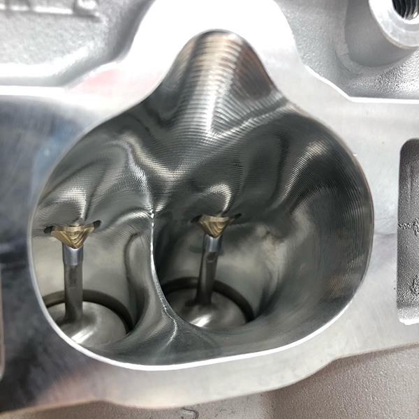
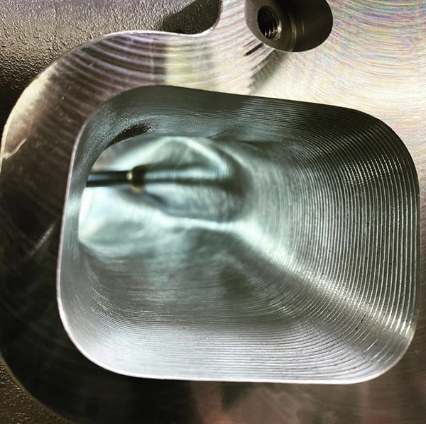
CNC’d EJ intake port done by Arlington Machine. Photo from Arlington Machine
“Designing an induction system is an iterative process – meaning everything I do depends on the move I just made previous to that,” Morgan says. “To understand proper airflow, you need to know the engine size, intended use, rpm range, and fuel being used. That tells you how much airflow you’re going to need. There’s a million ways to get 420 cfm, but there’s only one right way.”
Every single cylinder head is engine specific based on the engine’s intended use. Two engines that make the same exact power at the same rpm will have different induction system designs whether they are a jet boat engine, truck or tractor pull engine, or a drag engine. Just as different applications will vary, so too will boosted engine set ups versus naturally aspirated engines.
“If you’re using a high-helix roots-type supercharger on alcohol, the port volumes will change and the runner length is insignificant,” he says. “The harmonics will also be out of the picture. With a turbocharger, the intake induction length is almost identical to an NA engine. The runners can be shorter, but not larger than an NA engine. It’s not the airspeed that changes, it’s the density.”
The standard is cubic feet per minute. There’s no measurement for density, so it doesn’t matter whether it contains double the amount of air molecules – it’s still a cubic foot passing through.
“The displacement volume of the engine doesn’t change, so the velocity doesn’t change, just the density of the charge changes,” Morgan says. “Making the port bigger slows the air down and hurts power. Many people think since they’re moving twice the amount of fuel and air through there, they need the port to be twice as big. It doesn’t work that way. Ninety percent of the time it doesn’t need to change at all.
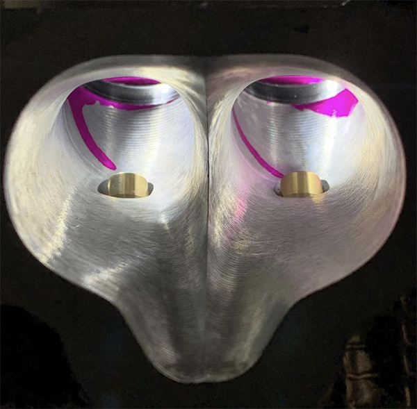
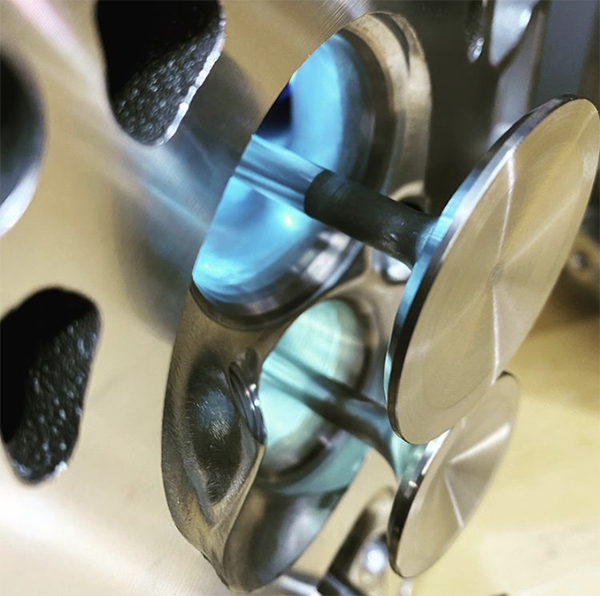
Airflow capacity isn’t everything. Characteristics that are far more important include airspeed, port cross-section, port volume and shape, and the relationship between the size of the throat and the valve seat. Photo from 4 Piston Racing.
“The biggest thing that changes on supercharged engines is the exhaust side. The intake to exhaust size ratio changes, the intake to exhaust flow ratio needs to change and the exhaust port changes dramatically.
“A turbocharged engine would want a smaller exhaust port than an NA engine would to help keep the airspeed up and help spool the turbo. A supercharged engine will want a gigantic exhaust port, because you don’t want any back pressure.”
The cylinder head needs to have a flow that is reasonably compatible with the expectations of its use. For that reason, different combinations require different sized ports, different length runners, different manifolds, and different camshafts.
Airspeed Over Airflow
Cylinder heads can often be close to one another volume-wise, but they can vary drastically in flow curve. People mistakenly believe that if they buy a cylinder head that flows more air and has a big cfm number, they’re going to make more power. However, big flow numbers will be useless to an engine builder without knowing all the other variables you need.
The factors that determine the performance of a cylinder head are complex. A head that is ported without considering airspeed, the size of the engine, the rpm range, the location of the valves, and a dozen other parameters isn’t going to be the best head, regardless of its peak airflow.
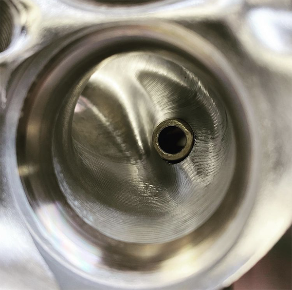
This is an L83 port. Photo from CT Performance.
There are many questions that are much more important than airflow: How far are the valve heads off the cylinder wall? What’s the ratio of valve size to bore diameter? What’s the ratio of the airflow to the size of the valve? What’s the size of the port, what’s its taper, how high is the short-side radius? The answers to these aren’t as simple as comparing a flow number, but they are what really make a difference in an engine.
“When I flow test a cylinder head, the cfm number is the last thing I look at,” Morgan says. “The flow bench tells me airspeed, and there are really three rules to making horsepower – airspeed, airspeed, airspeed. We design a port that has to flow X amount of air, but it also has to have X amount of average velocity, X amount of peak velocity, and you have to tune the runner harmonically on the system and on the bench itself. If you design the port properly, it will automatically flow a lot of air.
“Let’s say you have a target airflow of 500 cfm to produce X amount of power. If your velocity isn’t right, you’re never going to be able to utilize that 500 cfm. Everything is based on the instantaneous velocity, the average velocity, the harmonic wave tuning in the system, and how fast your accelerating the air.”
When you’re flow bench testing, you’re trying to draw correlation between what you’re seeing on the flow bench and what’s happening in the running engine. For that reason, you need to know where a cylinder head’s airspeed was taken – was it at the primary choke, the pushrod, the throat, or the short turn? Was that an average airflow number or peak airflow?
“People can get lost really quick,” Morgan admits. “On an NA application, the average airspeed range is 245-280, depending on the use. Unlimited applications like a Pro Stock set up would be around 265-275. An NHRA Super Stock engine would be at 300-315. However, you can’t draw conclusions from any of this stuff. It’s all engine specific. Regardless of the cfm, the velocity has to be there or it won’t make any power.”
So you’ve put a cylinder head on a flow bench and you have a bunch of numbers. What do those mean? Morgan looks at the discharge coefficient.
This Evo IV head was hand ported by Arlington Machine.
“The discharge coefficient is using the area available to me at maximum efficiency,” he says. “If you don’t have a high discharge coefficient, you can’t pull fuel, you can’t move air through the engine and it won’t accelerate. Secondly, average airspeed in the system has to fall in the 246-268 feet per second range. The peak velocity should not exceed, depending on piston speed and other factors, between 285-310 feet per second at the tightest area in the port. Two-valve, push-rod engines have a pinch point and no matter how we avoid it, we always end up with a slight pinch point. That pinch point’s airspeed should never exceed 300, and if you do that, you know you’re safe.”
Port and Throat Shape
The throat shape itself, the venturi section, is the fastest average airspeed section in the induction system. The fastest instantaneous area speed is at the apex of the short turn. The fastest average airspeed is right at the throat, or at least it should be.
“A lot of people miss that,” Morgan says. “In a perfect world, you want the airspeed to be the same all the way around the valve, but that’s not going to happen. You’re going to have 50-70 feet per second difference from one side of the port to the other. Our job as head porters is to minimize as much of that as possible. We have to utilize more of that throat at a higher efficiency level. If you do, it’s going to drop the pressure at the throat harder, which means it’s going to pull harder on the carburetor, so the engine will accelerate much faster.”
You could have two engines on the dyno that both make the same amount of power, but the one with the throat done properly will out accelerate and pull more fuel through than the one with the throat messed up.
“You have to have a certain size throat in order to get X airspeed and fill the cylinder,” he says. “With a two-valve head, if you set your throat at 90% of the valve diameter (valve diameter times .9) that is the all-around best throttle response, acceleration, best average power. If your throat goes over 92% valve diameter, you begin to lose horsepower quickly.
“At 91% valve diameter you could see more top end power. At 91.5%-91.8%, you’re getting dangerously close to critical max. This throat should only be used with an .800˝- 1˝ lift or higher camshaft. That said, you need to have an engine with super high engine speeds for it to work in your favor.”
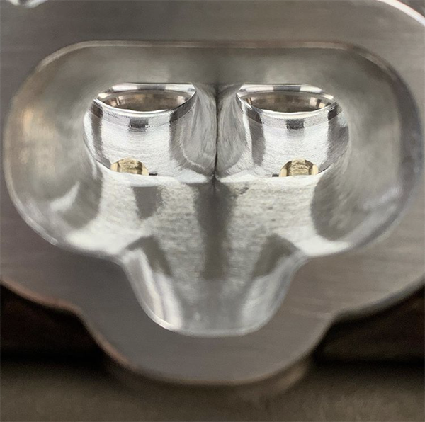
L83 DI head. Photo from CT Performance.
With 4-valve heads, the ratios change dramatically. Four-valve induction systems operate off of the average airspeed. Two-valve induction systems work off of instantaneous and average airspeeds in conjunction with one another.
“With a 4-valve head, you need really small throats because there’s no lift,” he says. “For a 4-valve head, your throat should be 86% valve diameter to see the best average power, throttle response and acceleration. At 87%, you see some more top end power. At 88%, you get the best overall power band, but you need to be in the .500˝ lift range. If you go to 89% and higher, that’s when you see negative reactions.”
Much like throat shape, port shape is something people have to understand in order to maximize a cylinder head’s efficiency. However, depending on that port location, your options might be limited.
“The port shape itself shouldn’t impact the air velocity profile in terms of average velocity or instantaneous velocity,” Morgan says. “An oval port should carry those velocities more even throughout. It reduces the velocity gradients from roof to floor and side to side. With a square port, the corners are dead. There’s no air in the corners. Anytime the fuel is present in that area, it’s going to fall out of suspension more.
“With an oval port, the air/fuel mixture is more homogenous and it carries the air/fuel mixture better and it’s easier to control the airspeed. However, if the port is too low, you can’t utilize an oval port.”
Morgan gives the example of a 23-degree small block Chevy and a 426 Hemi – you almost never see oval ports because you’re always struggling to get enough port area in those heads. To create power, you have to make the ports square.
“The only times you can use an oval port is when you have a clean sheet of paper and you can raise the port up high enough and aim it properly in order to utilize that shape,” Morgan says. “Otherwise, you’re usually struggling to get more port shape in something and you have to go more and more square. By doing that you’re making the situation less efficient, but you’re still getting more air in the engine and you’re going to make more power even though the shape isn’t optimal.”
Valve & Seat Configuration
In relation to airspeed, valve and seat configuration is another important area in the induction system, because it controls the air entering the cylinder.
The tulip shape of the valve is very important, but you can’t always have a ‘perfect’ tulip shape.
“We want to make that area as efficient as possible,” he says. “Flowing the most air is easy, but it won’t have any airspeed, so there is a give and take there and a balance that has to be struck between the mean airspeed, peak airspeed and airflow.”
When it comes to valves, consider that your two base options are to have a nailhead valve versus a tuliped valve. These two designs create different discrepancies in the space between the valve and throat of the cylinder head as air is passing. The nailhead design creates varying space, while a tuliped valve has equal spacing as air passes, which creates more airspeed.
“This results in a longer power band and a wider power band,” Morgan says. “The engine will come on the cam sooner and leave later. You’ll have more over rev. You can drop back down into higher rpms on the shift. Everything gets better with a tuliped exhaust valve.
“The tuliped valve creates a decrease in space between the throat and the valve, so as air enters, there is a constant acceleration of air to the throat. This is called pressure recovery. It recovers the pressure underneath the head of the valve, so it smooths the flow out and the flow goes way up on a running engine.”
Stabilizing the flow curve so it is smoother and silent is exactly what you should have with an exhaust port. It shouldn’t be turbulent at all.
“If you lay your combustion chamber back too much, your flow lines converge and it chokes the flow zone down,” he says. “When you choke that flow zone down, you make less power. Period. It works exactly the same on the exhaust side underneath the valve head.”
The tulip shape of the valve is very important, but you can’t always have a ‘perfect’ tulip shape. A lot of engines operate at extremely high engine speeds, so you have to make compromises to accommodate that.
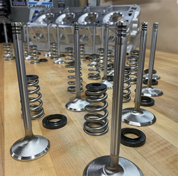
Hemi valves. Photo from Arlington Machine.
“Because you need a big tulip valve to make power and torque, that valve weight is going to be heavier,” he says. “With a heavier valve weight, you can’t turn the higher engine speeds, so your valvetrain will go crazy. To remedy that, you have to take tulip out and lighten the valve up, which then hurts exhaust flow, but you have little choice.”
Conclusion
Again, there’s much more to cylinder heads than just cfm, and that’s where people make what amounts to wrong decisions. Airflow capacity isn’t everything. Characteristics that are far more important include airspeed, port cross-section, port volume and shape, and the relationship between the size of the throat and the valve seat.
If these attributes are wrong, you can work forever on the flow bench and not overcome the fundamental flaws. The next time you’re considering a cylinder head or reading the data from a flow bench, make sure you understand all the necessary data for your engine and application. EB
The complexity of cylinder head set up and flow bench testing comes in the form of math, aerodynamics, thermodynamics, and the physics it takes to design the correct port and manifold design for a particular engine combination. These processes take years to master.
By
Greg Jones
on
Mar 26, 2021
Understanding Airspeed & Airflow
For years now, many folks in the industry have become solely fixated on cubic feet per minute (cfm) numbers when it comes to the performance of cylinder heads. This fixation places importance on a number that is easily manipulated, while ignoring other data about a cylinder head’s performance. This singular thinking is wrong and won’t do you any favors come race day if you ignore all the other aspects that help the induction system deliver performance.
Ported Brodix heads. Photo from CT Performance.
Experienced cylinder head designers and head porters often tell people not to pay attention to flow numbers, but that does not mean that flow numbers don’t matter. This distinction is often lost in translation. Flow numbers are important, and they do have meaning – just not the meaning most people attribute. Airflow numbers give insight into the potential for power. However, they don’t guarantee you will make more power.
Flow numbers are just one variable used for various equations to analyze port characteristics in a very complex system. You can have 10 different ports with the same exact flow numbers, yet they can vary wildly in rpm range, acceleration and power. The complexity of cylinder head set up and flow bench testing comes in the form of math, aerodynamics, thermodynamics, and the physics it takes to design the correct port and manifold design for a particular engine combination. These processes take years to master, so we got insight from induction system expert Darin Morgan, who is now with BES Racing Engines in Guilford, IN. Here is a deeper look into induction system flow characteristics and what you really need to know to have the right set up for your engine.
Understand Your End Goal
No surprise here! Like in anything you do for a new engine build, you have to start by knowing everything about what a particular engine will be used for, what’s inside and what the end goal of the build is.
CNC’d EJ intake port done by Arlington Machine. Photo from Arlington Machine
“Designing an induction system is an iterative process – meaning everything I do depends on the move I just made previous to that,” Morgan says. “To understand proper airflow, you need to know the engine size, intended use, rpm range, and fuel being used. That tells you how much airflow you’re going to need. There’s a million ways to get 420 cfm, but there’s only one right way.”
Every single cylinder head is engine specific based on the engine’s intended use. Two engines that make the same exact power at the same rpm will have different induction system designs whether they are a jet boat engine, truck or tractor pull engine, or a drag engine. Just as different applications will vary, so too will boosted engine set ups versus naturally aspirated engines.
“If you’re using a high-helix roots-type supercharger on alcohol, the port volumes will change and the runner length is insignificant,” he says. “The harmonics will also be out of the picture. With a turbocharger, the intake induction length is almost identical to an NA engine. The runners can be shorter, but not larger than an NA engine. It’s not the airspeed that changes, it’s the density.”
The standard is cubic feet per minute. There’s no measurement for density, so it doesn’t matter whether it contains double the amount of air molecules – it’s still a cubic foot passing through.
“The displacement volume of the engine doesn’t change, so the velocity doesn’t change, just the density of the charge changes,” Morgan says. “Making the port bigger slows the air down and hurts power. Many people think since they’re moving twice the amount of fuel and air through there, they need the port to be twice as big. It doesn’t work that way. Ninety percent of the time it doesn’t need to change at all.
Airflow capacity isn’t everything. Characteristics that are far more important include airspeed, port cross-section, port volume and shape, and the relationship between the size of the throat and the valve seat. Photo from 4 Piston Racing.
“The biggest thing that changes on supercharged engines is the exhaust side. The intake to exhaust size ratio changes, the intake to exhaust flow ratio needs to change and the exhaust port changes dramatically.
“A turbocharged engine would want a smaller exhaust port than an NA engine would to help keep the airspeed up and help spool the turbo. A supercharged engine will want a gigantic exhaust port, because you don’t want any back pressure.”
The cylinder head needs to have a flow that is reasonably compatible with the expectations of its use. For that reason, different combinations require different sized ports, different length runners, different manifolds, and different camshafts.
Airspeed Over Airflow
Cylinder heads can often be close to one another volume-wise, but they can vary drastically in flow curve. People mistakenly believe that if they buy a cylinder head that flows more air and has a big cfm number, they’re going to make more power. However, big flow numbers will be useless to an engine builder without knowing all the other variables you need.
The factors that determine the performance of a cylinder head are complex. A head that is ported without considering airspeed, the size of the engine, the rpm range, the location of the valves, and a dozen other parameters isn’t going to be the best head, regardless of its peak airflow.
This is an L83 port. Photo from CT Performance.
There are many questions that are much more important than airflow: How far are the valve heads off the cylinder wall? What’s the ratio of valve size to bore diameter? What’s the ratio of the airflow to the size of the valve? What’s the size of the port, what’s its taper, how high is the short-side radius? The answers to these aren’t as simple as comparing a flow number, but they are what really make a difference in an engine.
“When I flow test a cylinder head, the cfm number is the last thing I look at,” Morgan says. “The flow bench tells me airspeed, and there are really three rules to making horsepower – airspeed, airspeed, airspeed. We design a port that has to flow X amount of air, but it also has to have X amount of average velocity, X amount of peak velocity, and you have to tune the runner harmonically on the system and on the bench itself. If you design the port properly, it will automatically flow a lot of air.
“Let’s say you have a target airflow of 500 cfm to produce X amount of power. If your velocity isn’t right, you’re never going to be able to utilize that 500 cfm. Everything is based on the instantaneous velocity, the average velocity, the harmonic wave tuning in the system, and how fast your accelerating the air.”
When you’re flow bench testing, you’re trying to draw correlation between what you’re seeing on the flow bench and what’s happening in the running engine. For that reason, you need to know where a cylinder head’s airspeed was taken – was it at the primary choke, the pushrod, the throat, or the short turn? Was that an average airflow number or peak airflow?
“People can get lost really quick,” Morgan admits. “On an NA application, the average airspeed range is 245-280, depending on the use. Unlimited applications like a Pro Stock set up would be around 265-275. An NHRA Super Stock engine would be at 300-315. However, you can’t draw conclusions from any of this stuff. It’s all engine specific. Regardless of the cfm, the velocity has to be there or it won’t make any power.”
So you’ve put a cylinder head on a flow bench and you have a bunch of numbers. What do those mean? Morgan looks at the discharge coefficient.
This Evo IV head was hand ported by Arlington Machine.
“The discharge coefficient is using the area available to me at maximum efficiency,” he says. “If you don’t have a high discharge coefficient, you can’t pull fuel, you can’t move air through the engine and it won’t accelerate. Secondly, average airspeed in the system has to fall in the 246-268 feet per second range. The peak velocity should not exceed, depending on piston speed and other factors, between 285-310 feet per second at the tightest area in the port. Two-valve, push-rod engines have a pinch point and no matter how we avoid it, we always end up with a slight pinch point. That pinch point’s airspeed should never exceed 300, and if you do that, you know you’re safe.”
Port and Throat Shape
The throat shape itself, the venturi section, is the fastest average airspeed section in the induction system. The fastest instantaneous area speed is at the apex of the short turn. The fastest average airspeed is right at the throat, or at least it should be.
“A lot of people miss that,” Morgan says. “In a perfect world, you want the airspeed to be the same all the way around the valve, but that’s not going to happen. You’re going to have 50-70 feet per second difference from one side of the port to the other. Our job as head porters is to minimize as much of that as possible. We have to utilize more of that throat at a higher efficiency level. If you do, it’s going to drop the pressure at the throat harder, which means it’s going to pull harder on the carburetor, so the engine will accelerate much faster.”
You could have two engines on the dyno that both make the same amount of power, but the one with the throat done properly will out accelerate and pull more fuel through than the one with the throat messed up.
“You have to have a certain size throat in order to get X airspeed and fill the cylinder,” he says. “With a two-valve head, if you set your throat at 90% of the valve diameter (valve diameter times .9) that is the all-around best throttle response, acceleration, best average power. If your throat goes over 92% valve diameter, you begin to lose horsepower quickly.
“At 91% valve diameter you could see more top end power. At 91.5%-91.8%, you’re getting dangerously close to critical max. This throat should only be used with an .800˝- 1˝ lift or higher camshaft. That said, you need to have an engine with super high engine speeds for it to work in your favor.”
L83 DI head. Photo from CT Performance.
With 4-valve heads, the ratios change dramatically. Four-valve induction systems operate off of the average airspeed. Two-valve induction systems work off of instantaneous and average airspeeds in conjunction with one another.
“With a 4-valve head, you need really small throats because there’s no lift,” he says. “For a 4-valve head, your throat should be 86% valve diameter to see the best average power, throttle response and acceleration. At 87%, you see some more top end power. At 88%, you get the best overall power band, but you need to be in the .500˝ lift range. If you go to 89% and higher, that’s when you see negative reactions.”
Much like throat shape, port shape is something people have to understand in order to maximize a cylinder head’s efficiency. However, depending on that port location, your options might be limited.
“The port shape itself shouldn’t impact the air velocity profile in terms of average velocity or instantaneous velocity,” Morgan says. “An oval port should carry those velocities more even throughout. It reduces the velocity gradients from roof to floor and side to side. With a square port, the corners are dead. There’s no air in the corners. Anytime the fuel is present in that area, it’s going to fall out of suspension more.
“With an oval port, the air/fuel mixture is more homogenous and it carries the air/fuel mixture better and it’s easier to control the airspeed. However, if the port is too low, you can’t utilize an oval port.”
Morgan gives the example of a 23-degree small block Chevy and a 426 Hemi – you almost never see oval ports because you’re always struggling to get enough port area in those heads. To create power, you have to make the ports square.
“The only times you can use an oval port is when you have a clean sheet of paper and you can raise the port up high enough and aim it properly in order to utilize that shape,” Morgan says. “Otherwise, you’re usually struggling to get more port shape in something and you have to go more and more square. By doing that you’re making the situation less efficient, but you’re still getting more air in the engine and you’re going to make more power even though the shape isn’t optimal.”
Valve & Seat Configuration
In relation to airspeed, valve and seat configuration is another important area in the induction system, because it controls the air entering the cylinder.
The tulip shape of the valve is very important, but you can’t always have a ‘perfect’ tulip shape.
“We want to make that area as efficient as possible,” he says. “Flowing the most air is easy, but it won’t have any airspeed, so there is a give and take there and a balance that has to be struck between the mean airspeed, peak airspeed and airflow.”
When it comes to valves, consider that your two base options are to have a nailhead valve versus a tuliped valve. These two designs create different discrepancies in the space between the valve and throat of the cylinder head as air is passing. The nailhead design creates varying space, while a tuliped valve has equal spacing as air passes, which creates more airspeed.
“This results in a longer power band and a wider power band,” Morgan says. “The engine will come on the cam sooner and leave later. You’ll have more over rev. You can drop back down into higher rpms on the shift. Everything gets better with a tuliped exhaust valve.
“The tuliped valve creates a decrease in space between the throat and the valve, so as air enters, there is a constant acceleration of air to the throat. This is called pressure recovery. It recovers the pressure underneath the head of the valve, so it smooths the flow out and the flow goes way up on a running engine.”
Stabilizing the flow curve so it is smoother and silent is exactly what you should have with an exhaust port. It shouldn’t be turbulent at all.
“If you lay your combustion chamber back too much, your flow lines converge and it chokes the flow zone down,” he says. “When you choke that flow zone down, you make less power. Period. It works exactly the same on the exhaust side underneath the valve head.”
The tulip shape of the valve is very important, but you can’t always have a ‘perfect’ tulip shape. A lot of engines operate at extremely high engine speeds, so you have to make compromises to accommodate that.
Hemi valves. Photo from Arlington Machine.
“Because you need a big tulip valve to make power and torque, that valve weight is going to be heavier,” he says. “With a heavier valve weight, you can’t turn the higher engine speeds, so your valvetrain will go crazy. To remedy that, you have to take tulip out and lighten the valve up, which then hurts exhaust flow, but you have little choice.”
Conclusion
Again, there’s much more to cylinder heads than just cfm, and that’s where people make what amounts to wrong decisions. Airflow capacity isn’t everything. Characteristics that are far more important include airspeed, port cross-section, port volume and shape, and the relationship between the size of the throat and the valve seat.
If these attributes are wrong, you can work forever on the flow bench and not overcome the fundamental flaws. The next time you’re considering a cylinder head or reading the data from a flow bench, make sure you understand all the necessary data for your engine and application. EB
Last edited: