air /fuel meters and tuning

Grumpy

The Grumpy Grease Monkey mechanical engineer.
Staff member
thats a good question for this forum,
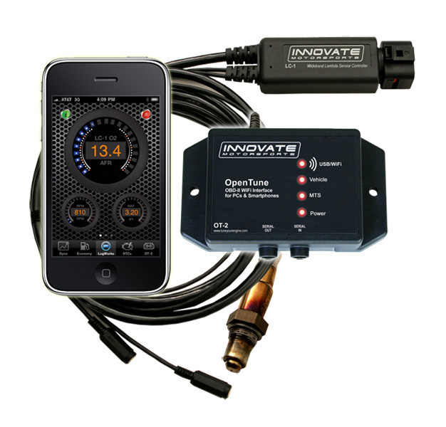
Ok Ive got one and have tested several of them.
I YOUR HAVING ISSUES< WITH THE CAR RUNNING CORRECTLY,LOOK FOR LOOSE OR CORRODED ELECTRICAL WIRING CONNECTORS, in THE WIRING HARNESS, and VERIFY YOUR FIRING ORDER, YEAH I KNOW YOUR SURE ITS CORRECT, CHECK IT CAREFULLY AGAIN, YOUR NOID TEST LIGHT AND MULTI- METER CAN SAVE YOU A GREAT DEAL OF PROBLEMS AND SCRATCHING YOUR HEAD IF YOU TEST BASIC ELECTRICAL CONNECTIONS< RESISTANCE AND VOLTAGE, CHECK YOUR SENSORS AND GROUNDS, A SHOP MANUALS MANDATORY, HEAT SENSORS AND IGNITION MODULES AND OIL PRESSURE SENSORS HAVE A LONG TRACK RECORD OF FAILING OR PARTIALLY AND INTERMITTENTLY NOT FUNCTIONING
fuelaratio1b.jpg


http://www.autometer.com/tech_faq_answe ... d=1&qid=48

http://www.innovatemotorsports.com/products/lm2.php

http://www.jegs.com/c/Gauges-Tachs_Air- ... 5/10002/-1

http://www.lethalperformance.com/05-201 ... io-p-18965

http://www.aa1car.com/library/wraf.htm

http://www.modernperformance.com/product_info.php?manufacturers_id=&products_id=1149

http://www.3barracing.com/product_3.htm

http://www.rbracing-rsr.com/rsrgauge.htm

http://www.scirocco.org/tech/misc/afgauge/af.html

http://www.innovatemotorsports.com/products/lm1.php

http://www.autospeed.com/cms/A_0217/article.html?popularArticle

http://thedynoshop.net/prod01.htm

heres my take on them, short answer, they are a big help but a P.I.T.A. to set up and use if your not going to semi permenantly install them on your car.

Stoich.gif

IVE come to use reading spark plug condition,

http://www.digitalcorvettes.com/forums/showthread.php?t=80783

http://www.digitalcorvettes.com/forums/showthread.php?t=85537&highlight=plugs

use of a good timing light and vacuum gauge , fuel pressure gauge and use of a GOOD HIGH TEMP INFARED THERMOMETER (THIS ONE)

http://www.professionalequipment.co...hermometer-501-ds-42545/infrared-thermometer/

as a very quick to use and accurate set of tools. :thumbsup:

OK WHY???

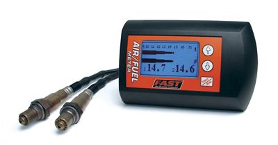
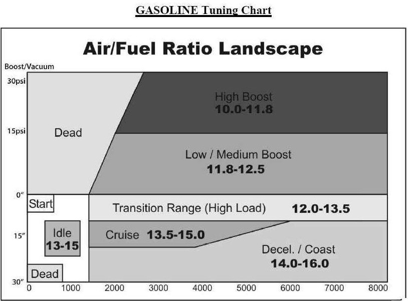
well your main concern when tuning an engine is to keep the all the cylinders running aproximately the same ratio and at about 12.8:1 for max power up to about 14.7:1 for low emmissions and good mileage, AND WHILE A A/F GAUGE IS A GREAT ASSET, ITS EASY TO DAMAGE, AND ITS BEST INSTALLED IN YOUR CAR , NOT USED AS A SHOP TOOL.

so whats the advantage/disadvantages

a fuel air meter uses a o2 sensor, if you place it in the header collector it gives an AVERAGE of all the cylinders on that cylinder head,If theres an (X) installed close to the dual collectors reversion pulses can occasionally even give data from the other side of the engine, so in theory and in practice you can have two cylinders run lean and two rich and the AVERAGE tends to look RICH to the O2 sensor as it SEES unburnt fuel, if you place it in the individual primary header tubes you either need eight O2 sensors (VERY EXPENSIVE, and keeping the wires from burning or grounding outs a TOTAL P.I.T.A......IF you don,t succeed you destroy the O2 sensor and need to replace it.) or you need to be constantly swapping very hot and fragile O2 sensors and bung plugs constantly, but with the IR thermometer you can almost instantly see which cylinders are running hotter or cooler and adjust the jets or look for vacuum leaks, or other CAUSED for the TEMP DIFFERANCE, ETC, far faster too get all the cylinders running at approximately the same temp, indicating the same fuel air ratio, youll be amazed at how close the temp follows the fuel/air ratio, and you can confirm it with plug condition and the other test equipment. run any cylinder too lean and detonation can break rings or melt pistons, run it too rich and you can wash the oil off the cylinder walls and ruin rings/scuff pistons, you need to know whats going on in EACH CYLINDER not the AVERAGE of all cylinders.

SO, if your going to install a decent wide band fuel air ratio meter on your car thats fine, its going to be an asset to your tunning skills, if you install the indicator/gauge inside the car and weld in a couple extra bungs in the collectors for tunning and wide band O2 sensors which are a big help, but you will quickly find that its a P.I.T.A. to use it for tune ups on all your buddies cars with the welding collector bungs and installing plugs and O2 sensors while the IR thermometer route is fast and very simple and you can confirm with oplug reading the condition of the engine.

YEAH! theres meters that you can stick in a tail pipe, but they read THE AVERAGE, not the individual cylinders ,
think about AVERAGEs
AS my old physics proffesor once said,
IF, I pour molten lead in your front slacks pockets and pack your butt in solid with DRY ICE,.... ON AVERAGE your comfortable:D


BTW
http://www.digitalcorvettes.com/forums/showthread.php?t=79676


bits of useful info on these

http://www.thirdgen.org/o2tuning

http://www.thirdgen.org/fuelgauge

http://www.thirdgen.org/tpimod2

http://www.thirdgen.org/injectorswap

http://www.thirdgen.org/coolantbypass

http://www.mummbrothers.com/SRF_Stuff/Secrets/Driveline/Air_Fuel.htm

http://www.ws6.com/mycar.htm

leon posted this bit of info
"Exhaust gas temperature (EGT) depends on combustion temperatures. The hotter the mixture burns inside the cylinder, the hotter it will be coming out. Theoretically, combustion temperatures are at a maximum at stoichiometric, but realistically the maximum occurs slightly rich from peak because of the dissociation of Oxygen from the combustion products (CO2, H2O). Why temperature drops when rich or lean is described by the energy released caused by the chemical reactions between the fuel and air. Too little fuel (lean) and there is less energy contained within and more heat is transferred to the cylinder walls (no fuel evaporation or boundary layer), thus the lower temperature when it burns. Too much fuel, and combustion efficiency drops thus generating less heat.

I know, this is not too detailed, but it gets the point across without involving too much technical jargon.

Of course, this all assumes MBT timing and stable combustion. You can also change exhaust temps by varying spark timing, arguably more so than by just varying AFR. EGT is increased when spark timing is retarded since you are giving the gasses in the cylinder less time to cool off before the exhaust valve opens. "
 
Excessive HC emissions may be caused by:

viewtopic.php?f=55&t=3522&p=9307&hilit=emissions#p9307

ignition system misfiring
Improper ignition timing (retarted)
excessively rich air/fuel ratio
low cylinder compression
defective valves, guides, or lifters
vacuum leaks

Excessive CO emissions may be caused by:

rich air/fuel mixture
dirty air filter
faulty injectors
higher-than-normal fuel pressures
defective system input sensor

Excessive HC and CO emissions may be caused by:

plugged PCV system
excessively rich air/fuel ratio
stuck open heat riser valve
AIR pump inoperative or disconnected
engine oil diluted with gasoline

Lower-than-normal O2 readings may be caused by:

rich air/fuel mixture
dirty air filter
faulty injectors
higher-than-normal fuel pressures
Restricted PCV system
charcoal canister purging at idle and low speeds

Lower-than-normal CO2 readings may be caused by:

leaking exhaust system
rich air/fuel mixture

Higher-than-normal O2 readings may be caused by:
an engine misfire
lean air/fuel mixture
vacuum leaks
lower-than-specified fuel pressures
defective fuel injectors
defective system input sensor
 
AND WHILE A A/F GAUGE IS A GREAT ASSET, ITS EASY TO DAMAGE, AND ITS BEST INSTALLED IN YOUR CAR , NOT USED AS A SHOP TOOL.

Really - I should keep my dual wide band O2 in there premanently? That's best for it? I yanked it out concerned that I might harm it. Would not mind having it in permanently...
 
obviously theres a wide variation in quality and most modern cars with EFI use oxygen sensors used in the exhaust of cars to do this type of sensor work and NOTHING ELECTRONIC in nature lasts forever,but the sensors are used to feed constant data on remaining un-burnt oxygen in the exhaust back to the computer controlling the fuel injector pulse duration,yes in some cases its potentially possible to damage the sensors, sensors normally last 3-6 years in service, but in most cases its not critical if properly installed , and not all that expensive or time consuming to replace them on occasion,so its not a big deal to suggest a dash mounted fuel/air ratio gauge be used as a tuning tool on a carburetor equipped engine, there even several BUILD IT YOURSELF F/A RATIO GAUGE KITS AVAILABLE
fuel_injectorv.jpg


http://tpiparts.net/emissions


Emissions Devices

Disclaimer: The information contained within this article is intended for educational purposes only. It may be illegal to remove, modify, or tamper with any emissions device on your vehicle, depending on the state in which you live. Please check your local rules and regulations to ensure that you abide by them.

Before we discuss how these systems operate, I would like to comment on a general misconception associated with fuel injection in general. I have heard on numerous occassions that fuel injection in general is too complicated and restrictive due to emissions devices. In reality, the problem lies with people assuming that the emissions components are somehow required as part of the whole fuel injection platform, and that these devices pose a significant restriction in performance. Just because you are running a fuel injection system, does not mean you will have emissions devices. In addition, having emissions equipment does not prevent someone from running whatever engine modifications they want. The loss in power from these emission devices is quite small.

As many of you already know, Tuned Port Injection engines were factory installed on vehicles that were required to be emissions compliant. To ensure that emissions requirements were met, GM used several devices to lower emissions output. Basically, these can be broken down into three main systems : EGR, A.I.R., and EECS. None of these are absolutely necessary to run a Tuned Port Injection intake, but may be legally necessary if you want to be street legal in the state where you live.

Exhaust Gas Recirculation System (EGR)

The sole purpose of the EGR system is to reduce the formation of Oxides of Nitrogen (NOx). These are formed when the temperature in the combustion chamber reaches very high levels. To avoid this situation, the EGR system is used to lower combustion chamber temperatures by admitting small amounts of exhaust gas back into the combustion chamber. As you can imagine, exhaust gas does not burn, and does not help the combustion process. If the EGR system would admit exhaust gas into the combustion chamber at idle, it would cause a rough idle, or stalling. As a result, EGR does not allow exhaust gas into the chamber at idle (nor at wide open throttle, more on that later...). To accomplish this, there has to be some way of controlling EGR flow.

The way this is accomplished is actually quite simple. First of all, there is a round, flying saucer - looking part that mounts on the intake manifold. This is called the EGR valve. There is an opening in the intake manifold from the cylinder head that allows exhaust gas to move up to the valve. When vacuum is applied to the valve, it allows the exhaust gases to pass. To control when the valve receives vacuum, an EGR solenoid is used. This part mounts on the passenger side near the back of the intake manifold. It has a vacuum line which supples ported manifold vacuum, and another vacuum line running to the EGR valve. When the ECM requests EGR to be ON, it sends a signal the the EGR solenoid, which then allows vacuum to be applied to the EGR valve. When the ECM wishes EGR to be off, the solenoid will cease to apply vacuum to the EGR valve.

The ECM will turn on the EGR solenoid by grounding it. It does this via pulse width modulation (PWM). This means that the ECM will turn on and off the solenoid many times a second. Just how many times this occurs will affect the amount of vacuum applied to the EGR valve, and therefore the amount of exhaust gas admitted into the combustion chamber. During the time that EGR is requested by the ECM, fuel output and spark advance are also altered. More timing is added, and the fuel mixture is leaned a bit.

During WOT (wide open throttle), the ECM shuts down EGR. Since EGR will play no role whatsoever under WOT, it will not impede the engine's ability to generate horsepower.

How does the ECM know if there is a problem with the EGR system? Well, the answer depends on what year TPI setup you have. If you have an 85-89 setup, then there will be a single wire that goes to the base of the EGR valve. This is basically a temperature switch. When the ECM requests EGR, it will check this wire to see if there is a change in temperature. If no change is detected, the ECM will think there is a problem with the system, and will throw a code 32. Most of the time, the problem is the temperature switch that is bad. However, you should first check for vacuum leaks, check that all vacuum lines are properly routed, check the harness connector at the EGR solenoid with a voltmeter, and make sure that the EGR passages are not clogged with deposits.

The 90-92 TPI setups did not use a temperature switch on the EGR base. Instead, the ECM monitors the MAP voltage to determine if an EGR request was successful or not. When EGR is turned on, engine vacuum will lower a little. The ECM will throw a code 32 if it suspects that the EGR request was not successful.

So what would someone gain by disabling EGR? Just about the only thing would be less parts under the hood. Basically, removing EGR gives you more space (although not much). To correctly disable EGR from your vehicle, you MUST at the very least, disable it in the prom. This is done by setting the minimum temperature to enable EGR to 151 degrees Celsius (maximum allowable temperature), and setting the minimum vehicle speed to enable EGR to 255 mph (maximum allowable speed). Since the engine will never reach either of these conditions, EGR will never be requested by the ECM. Since EGR will never be requested, it does not matter if you leave the EGR system all installed in its original place, or if you remove it from the car. If you decide to remove it, you will need an EGR block off plate to cover the hole in the intake manifold.

If you simply remove the EGR system from the car, but do not disable it in the ECM, you will run into significant problems. You will likely run into detonation, the engine will run very poorly, lack power, and will probably run on the hot side as well. In addition, you will get a code 32 before running very long. If you recall from before, the ECM alters fuel and spark advance when it thinks EGR should be on. If no EGR flow is possible because you removed it, you will have a lean condition which will be further aggravated by advanced timing.

I have not had a chance to discuss A.I.R or EECS (canister purge). I will finish the article as soon as I have some spare time, but I wanted to post the EGR section for the moment atleast.

90-92_diagnostic_codes.jpg

http://www.scirocco.org/tech/misc/afgauge/af.html

http://www.aces.edu/~parmega/efi/temp/wb/guide.html

viewtopic.php?f=27&t=3096&p=18612#p18612

viewtopic.php?f=55&t=3522&p=18430&hilit=diy+fuel+ratio#p18430

http://www.autospeed.com.au/cms/A_1716/ ... larArticle

http://www.autospeed.com.au/cms/A_0217/ ... larArticle

http://www.jaycar.com.au/productView.as ... BCATID=347

http://www.eagle-research.com/cms/store ... cer-manual

http://www.youtube.com/watch?v=sS6olf1o ... ure=fvwrel

http://www.youtube.com/watch?v=RizrDvP8 ... re=related

http://garage.grumpysperformance.co...o-you-failed-emmision-testing.3522/#post-9307

http://garage.grumpysperformance.com/index.php?threads/carb-tuning-info-and-links.109/

http://garage.grumpysperformance.com/index.php?threads/spark-plug-info.202/

http://garage.grumpysperformance.com/index.php?threads/timing-tabs-and-indicators.1015/

http://garage.grumpysperformance.com/index.php?threads/verifying-your-real-advance-curve.4683/

http://garage.grumpysperformance.co...ning-with-an-air-fuel-logger.6765/#post-25598

http://garage.grumpysperformance.com/index.php?threads/air-fuel-meters-and-tuning.268/#post-18435

http://garage.grumpysperformance.co...atio-or-infrared-thermometer.6174/#post-19287
 
Last edited by a moderator:
Yeah, thats because with the engine running the snesor has to be powered/hot.
Leaving an unpowered sensor in the exhaust will damage it. So if you have the sensor in the exhaust just dont leave it unpowered when your runnig the car and it will be fine(if its setup above the 9-3 O'clock position)
Also, its best to start the unit/heat the sensor just after the engine start, you dont want to cause moisture blast on the hot/heated sensor while the engine is first starting.
 
Groan - I guess we'll soon find out if I damaged it. I'll probably leave it in + hardwire. I just need to find a place to put it as dash real estate on my car is getting scarce...
 
I'd probably tune at 10.5 a/f me too at 24 psi lol
Better safe then sorry.

Am using this (i did want something that also log the RPM)
LM-2:
http://www.summitracing.com/parts/INN-3806/
I may try to make a TPS (potentiometer/resistor forming a voltage divider)using one of the input of the LM-2.

So far i could try only the OBD-II functions on a newer car, will try it completly next season(april 2k12 is where i plan to take the car out).
Just welded the bung last week and i managed to accidently leave the flange ferrule behind the bung. :/
 
How important is it to be capable of monitoring both sides of a V8 with a single 4-barrel on a dual plane manifold ??? Certainly one is better than nothing, but seems like you are only getting half the picture with one side. Love the idea of data logging, much easier to look over the data when you are NOT driving.

Whats has been your experience, any problems with just one sensor ???
 
while dual sensors is obviously close to ideal and having a dedicated sensor for each cylinder is ideal, Ive swapped sides on the sensors testing my corvettes engine in the past and had very similar results so I doubt its going to be a problem.

heres a tip posted elseware if you don,t want to weld in bungs for testing probes or sensors in your header collectors ,in your exhaust pipes or while measuring the fuel/air ratio while tuning
Innovate-3728.jpg

http://www.innovatemotorsports.com/xcar ... ctid=16141
inov1.jpg

http://www.innovatemotorsports.com/xcar ... 274&page=1
bytor said:
Another option is to use tail pipe clamp adapter (3728) on the end of your exhaust. It uses a venturi effect to sample exhaust gas while keeping air away from the sensor. You probably would not wont this setup for a permanent install but it would keep you from having to drill holes. With your short exhaust, I would not see any significant lag or delay in the readings. I have been to a few dyno shops and the all use something like this to capture AFR during dyno runs.

Innovate-3728.jpg

Understanding Block Learn Multiplier (BLM)


Understanding Block Learn Multiplier (BLM)
David Huinker
Introduction
In a nutshell, the Block Learn Multiplier (BLM) is the long term fuel adjustment that the ECM "learns" to keep the air/fuel ratio within acceptable parameters. The Integrator is the same idea, only for short term adjustments. Basically, these two strategies are used to make adjustments and adaptations to the ever changing loads, atmospheric conditions, and fuel quality to keep the car's air/fuel ratio correct for driveability and emissions.
Also, keep in mind that when we say Long Term or Short Term, we are talking in computer time, not human time. In our ECM the Long Term fuel adjustment (BLM) happens about twice per second, while the Short Term fuel adjustment (INT) happens about 20 times per second
What are "Cells"?

The fuel delivery strategy uses a two dimensional table that has four rows and four columns, for a total of 16 "cells". Each cell contains a Block Learn Multiplier (BLM) value (from 0 to 255), which represents a long-term fuel correction based on that cell's operating conditions over a relatively long period of time. Each BLM value in turn contains an integrator value (also from 0 to 255), which is a short term fuel correction based on immediate operating conditions. For both the Integrator and BLM values, a higher value represents a correction that adds fuel to the fuel mixture, due to higher injector pulse widths.
MAF / RPM0-800 rpm800-1100 rpm1100-1500rpm1500 +rpm
0 – 9 GPSCell 0Cell 1Cell 2Cell 3
9 – 20 GPSCell 4Cell 5Cell 6Cell 7
20 – 30 GPSCell 8Cell 9Cell 10Cell 11
30 - + GPSCell 12Cell 13Cell 14Cell 15
The table above depicts the BLM cell table that is held in the typical Turbo Regal ECM. As you can see, it is offset by rpm in the columns, and by airflow in the rows. The individual cells are numbered 0 through 15 (for a total of 16 cells). So, the cell being accessed at any given point in time is controlled by airflow versus rpm.
Let's take a few "for instances". Let's say the car is sitting in the driveway in Park, up to temperature, and just idling. In that case:
  • RPM = 750
  • MAF = 6
Since the RPM is very low and the MAF is very low, the car will be using the information in BLM Cell 0 to adjust the idle fuel mixture. The value contained in that cell is adjusted with the Integrator values (which change based on O2 readings, etc.).
Now, let’s go for a typical highway cruise, at about 65mph, on a nice flat road:
  • RPM = 1800
  • MAF = 22
Since the RPM is above the highest value in the column to the right, and the MAF is reading a value in the “third” row, we can see that the ECM is now accessing, and using the BLM value in cell 11. Cruise conditions will often move between cells 7 and 11 based on small changes in MAF, since the typical highway cruise value is between 15 and 25.
Typically when you pull away from a stop sign or traffic light in fairly normal circumstances, you’ll see that it takes only a second or so for the RPM to jump over the 1500 upper RPM limit, and the MAF (air flow) will very easily jump up over the 30 gps upper MAF limit. In this example the ECM will be using cell 15 (sometimes erroneously called the WOT cell) (WOT meaning Wide Open Throttle).
OK, So what's the BLM DO?

The BLM is a long term adjustment , which is stored pretty much permanently (unless you disconnect power to the ECM), to the fuel delivery calibration that results from the ECM "learning" the values while you are driving around. 128 is the ideal value, because it is the center point of the range 0-255. Above 128, and the ECM is adding fuel to compensate for a lean condition at a particular load and RPM. Below 128, and it represents a correction for a rich condition.
How does the Integrator play into this?
On a cold start the INT is set to 128 and kept there until the coolant reaches a threshold value, a timer says the engine has been running long enough, and the O2 sensor has warmed up and started responding. The ECM then sets the closed loop flag, which meansthat if other conditions are met (not in PE, DE, or DEFCO modes, primarily) the ECM uses the O2 sensor to control the INT. It adds to the INT in small increments until the O2 voltage goes above a threshold so the ECM knows the engine is now rich, then it starts subtracting from the INT until the O2 voltage goes below another threshold and the engine is lean. The ECM keeps cycling the INT, trying to keep the time spent rich equal to the time spent lean so it knows that the average is stoichiometric. If other conditions are met then the learn control flag is set and the ECM keeps a moving average of the INT values. If this average is not 128, it will add or subtract to the current BLM value to move the INT average towards 128. This is done a few times a second, without the INT ever having to get to an extreme value such as 90 or 150. The stock BLM range is 105 to 150, but even if the BLM has reached one of these limits the ECM is still able to keep the engine averaging stoichiometric so long as the INT is not also at a limit. For example, the BLM could be 150 and the INT ranging between 135 and 145.
If you have a scan tool or Direct Scan you can watch this process. The ALDL update rate will keep you from seeing all of the INT values but you will still see the long-term trends. Start the engine and let it warm up so that learn mode is enabled, then pull the vacuum hose off of the fuel pressure regulator. The fuel pressure will jump up 4-7 psi and the engine will go rich. The INT will drop below 128 and go down until the engine finally goes lean or a limit is reached, and will then go up and down over a range of maybe 10-20 units as the ECM keeps the engine bouncing between rich and lean, and the BLM will start dropping. As it does, the average INT will rise back to 128. Once the INT average is 128 the BLM will stop changing. Put the vacuum hose back on, the fuel pressure will drop, the engine will go lean, and the mirror image of the above will occur. The INT will rise, start bouncing up and down, the BLM will rise, and the INT average will eventually reach 128 and the BLM will stop changing again.
Summary
BLM values are divided in to "Cells" based on MAF vs. RPM. Within each cell, there typically values from 105-150 for the BLM. Within the BLM value, there are Integrator values, typically 105-150 also.
The Integrator is adjusted based on sensor feedback (primarily the O2 sensor) to make real time adjustments for varying conditions. If the adjustments cannot be made in a BLM value, then the BLM value is either increased (add fuel) or decreased (subract fuel) to compensate.
If you reach the "corner" of an individual cell and not further adjustment is possible, the car may not run correctly and there is a problem with the calibration or a critical sensor.
It all sounds very intimidating, but really isn’t. One must keep in mind that the changes that are being made, as in the INT for example it is happening at close to 20 times per second. Think of it this way; The INT is used to “drive” the BLM number toward a value needed to maintain stoiceometric A/F ratio. As in one of the examples above, make a radical change (such as removing the fuel pressure regulator’s hose) and watch the INT do it’s thing!! The INT will jump to a high value, and hover there while the BLM starts its “march” up the scale. As the BLM approaches the value needed to get the A/F ratio corrected you’ll see the INT value heading back down toward 128. Ideally, they will both meet at 128 at about the same time. It’s really neat stuff to watch.
 
Last edited by a moderator:
grumpyvette said:
while dual sensors is obviously close to ideal and having a dedicated sensor for each cylinder is ideal, Ive swapped sides on the sensors testing my corvettes engine in the past and had very similar results so I doubt its going to be a problem.
Thats good to hear and you can also make an average of both side reading and in some case you can configure the unit with this in mind, so while you have just one sensor it will display a reading that average both side together.

I did go the single channel route, but the unit is capable of dual channel so hopefully if i buy one more sensor it will work on dual channel :).
 
mathd said:
I did go the single channel route, but the unit is capable of dual channel so hopefully if i buy one more sensor it will work on dual channel :).
SWEET, twice as many numbers......I wonder what I could do with this and an Excel spreadsheet. I'm starting to get a ???? as I type on the keyboard now! :cool:
 
Indycars said:
SWEET, twice as many numbers......I wonder what I could do with this and an Excel spreadsheet. I'm starting to get a ???? as I type on the keyboard now! :cool:

Ummmm, Okaaaay! Indy, there is such a thing as too MUCH information... :D

My issue is the instructions on the water/meth say to tune first the carb for slightly lean. (!!!) Say 12:1. Then use the water/meth to tune and hit 11:1 as your target.

THAT seems like a scary way to tune.

I probably will take out ignition timing thru boost retard... reach 12:1 with carb only... add water/meth to reach 11:1... then experiment with pulling out boost retard.
 
DorianL said:
Indycars said:
SWEET, twice as many numbers......I wonder what I could do with this and an Excel spreadsheet. I'm starting to get a ???? as I type on the keyboard now! :cool:

Ummmm, Okaaaay! Indy, there is such a thing as too MUCH information... :D

My issue is the instructions on the water/meth say to tune first the carb for slightly lean. (!!!) Say 12:1. Then use the water/meth to tune and hit 11:1 as your target.

THAT seems like a scary way to tune.

I probably will take out ignition timing thru boost retard... reach 12:1 with carb only... add water/meth to reach 11:1... then experiment with pulling out boost retard.

Personally I do it oppositely start with a fat tune and pull fuel or add boost or timing until the knock sensor says I've gone to far than dial it back a bit little safer IMO. With water in the mix 11.0 isn't a bad target just watch the knock gauge.
 
DorianL said:
Indycars said:
SWEET, twice as many numbers......I wonder what I could do with this and an Excel spreadsheet. I'm starting to get a ???? as I type on the keyboard now! :cool:

Ummmm, Okaaaay! Indy, there is such a thing as too MUCH information... :D

My issue is the instructions on the water/meth say to tune first the carb for slightly lean. (!!!) Say 12:1. Then use the water/meth to tune and hit 11:1 as your target.

THAT seems like a scary way to tune.

I probably will take out ignition timing thru boost retard... reach 12:1 with carb only... add water/meth to reach 11:1... then experiment with pulling out boost retard.
I would probably tune using the Lambda instead of the A/F reading since your blend of gasoline and alchool.
Here is what my instruction sheet says:
The Stoichiometric AFR value is the AFR multiplier. So for (standard, unblended)
gasoline its 14.7. If you set it to 14.7 the LM-2 display will show 14.7 AFR for Lambda
1.0. If you set it to 6.4 (methanol) the LM-2 will show 6.4 AFR for Lambda 1.0.
You can look at Lambda as the percent of richness. If running Lambda 0.85 (12.5 AFR
for gasoline) you are running 15% rich. For methanol 15% rich means 5.44 AFR. That's
where the value of Lambda comes in. If you run blended fuels where you don't know the
stoich value, you look at Lambda and adjust to 10-20% rich, depending where your max
power is. The % value of richness required by an engine (for max power) does change
relatively little (fairly independent of fuel). But if for example you adjust an engine
running methanol to 12.5 AFR, you would be running so lean that it would probably not
even run
 
Back
Top