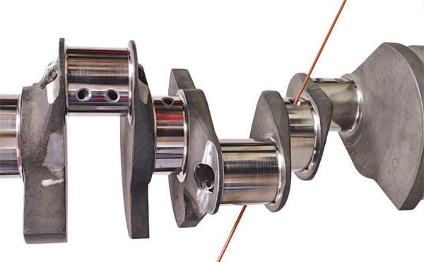
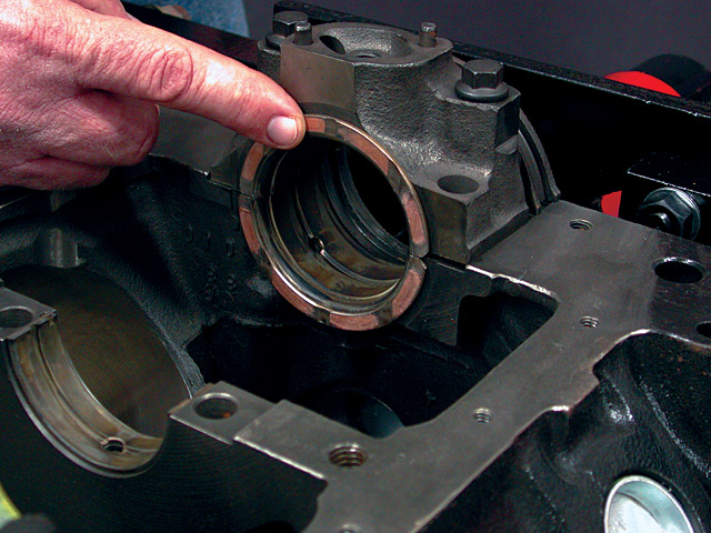
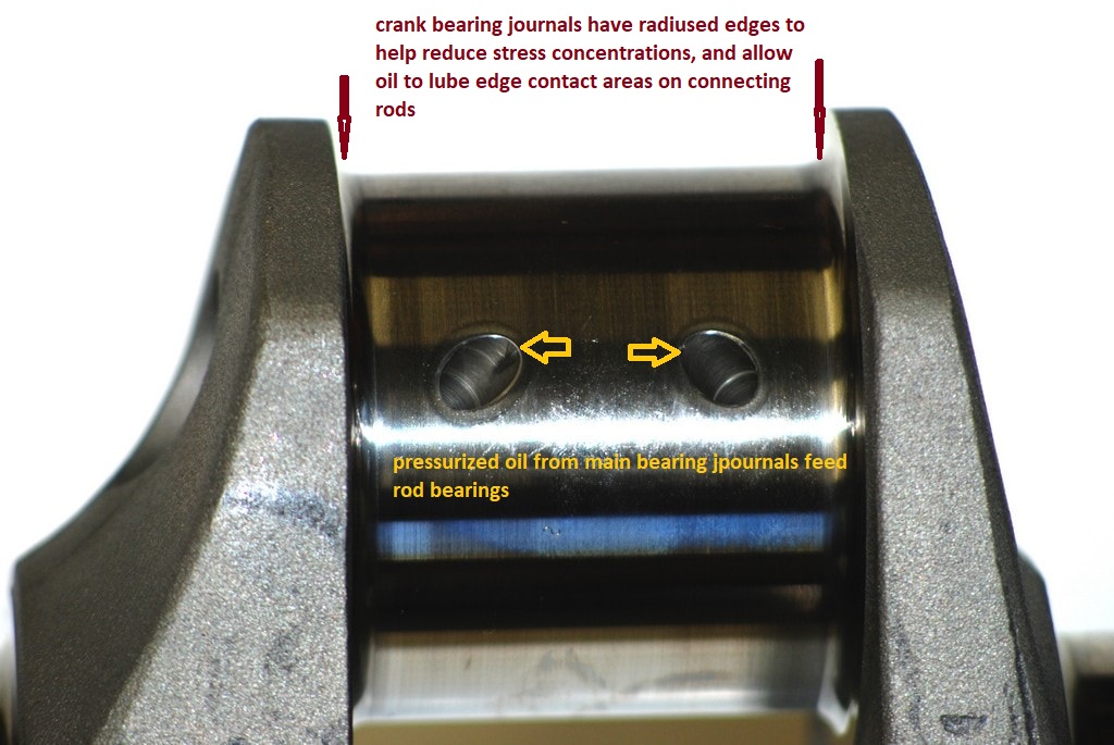
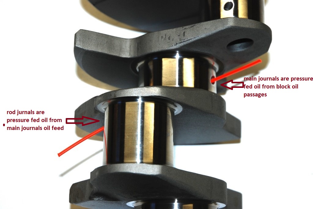
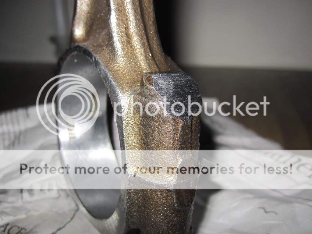
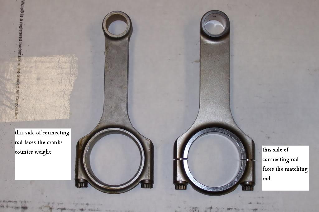
look closely at the connecting rods one edge of the main bearing are is beveled noticeably more than the other that beveled side faces away from the rod its paired with because it matches the slight radiased bevel of the crank journal
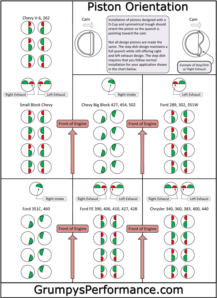
many builder class pistons are designed to go in, in either orientation ,and have both the valve notches and piston pin offset that are identical but most performance pistons have a dot or an F stamped on the crown indicating the side facing the front of the engine, naturally the rod big end bevels face the crank counter weights on each pair and the non-beveled big end faces the matched rod
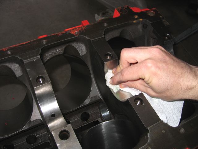
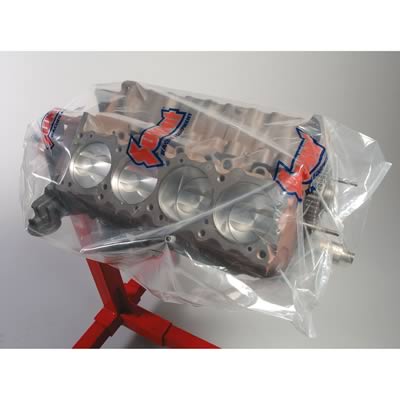
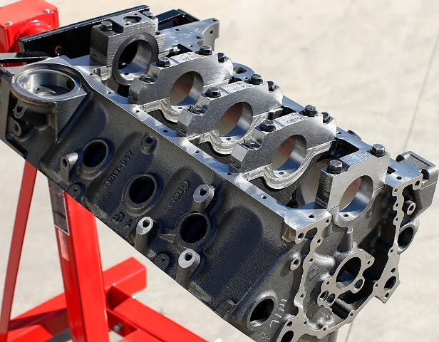
think carefully about both the initial cost and the structural strength of the engine block you select, the OEM blocks used in production car engines will RARELY accept a .030 plus over bore with out having one or more cylinders having marginally thin bore walls, this results in inadequate bore to ring sealing if its in the wrong area and promotes stress cracks. A .060 over bore in a SBC is rather commonly pushing that bore wall thickness up to or over a reasonable limit so you need to sonic and magnetically check the block for cracks and wall thickness.
you could easily dump $500-$1500 into machine work on a block that won,t last more than a few months under high stress if its not carefully checked PRIOR to the machine work being done.
https://www.amazon.com/dp/B06VXC1FPL/ref=nav_timeline_asin?_encoding=UTF8&psc=1
 www.youtube.com
 www.youtube.com
read the links don,t skip them, youll likely save a great deal of cash and time knowing whats involved
www.youtube.com
read the links don,t skip them, youll likely save a great deal of cash and time knowing whats involved
http://garage.grumpysperformance.com/index.php?threads/engine-balancing.3900/
http://garage.grumpysperformance.com/index.php?threads/block-prep.125/
http://garage.grumpysperformance.co...k-after-a-cam-lobe-rod-or-bearings-fail.2919/
http://garage.grumpysperformance.co...n-wrist-pins-one-really-over-looked-part.978/
http://garage.grumpysperformance.com/index.php?threads/engine-block-cylinder-wall-thickness.976/
http://garage.grumpysperformance.co...tion-of-crank-durring-short-blk-assembly.852/
http://garage.grumpysperformance.com/index.php?threads/why-build-a-383-vs-a-350.715/
http://garage.grumpysperformance.com/index.php?threads/blocks-from-summitt-or-comp-products.10174/
http://garage.grumpysperformance.co...s-why-doesn-t-anyone-ever-ask-or-check.11532/
http://www.bing.com/videos/search?q...&mid=E76F9F78364354FD222DE76F9F78364354FD222D
http://www.hotrod.com/techarticles/hrdp ... ting_rods/
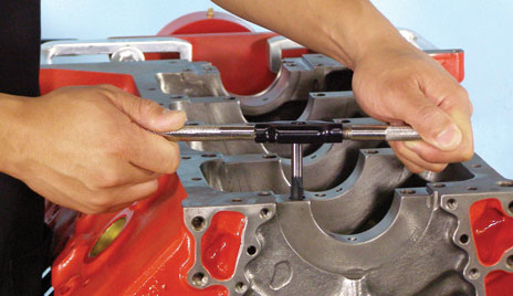
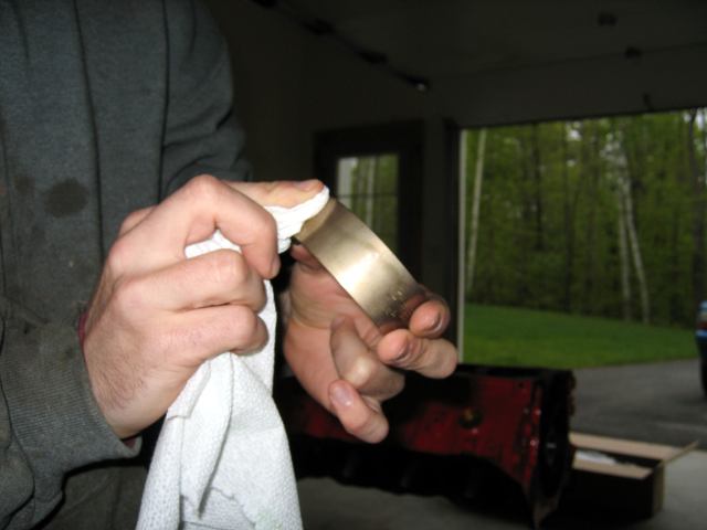
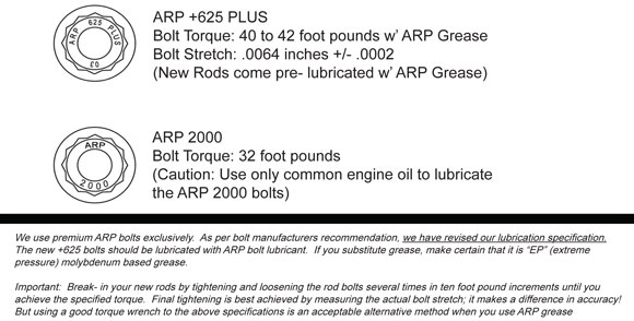
cleaning threads before assembly is always a good idea
check manufactures tech guide info
http://arp-bolts.mobi/p/tech.php?page=3
http://arp-bolts.mobi/p/tech.php?page=2
http://arp-bolts.com/
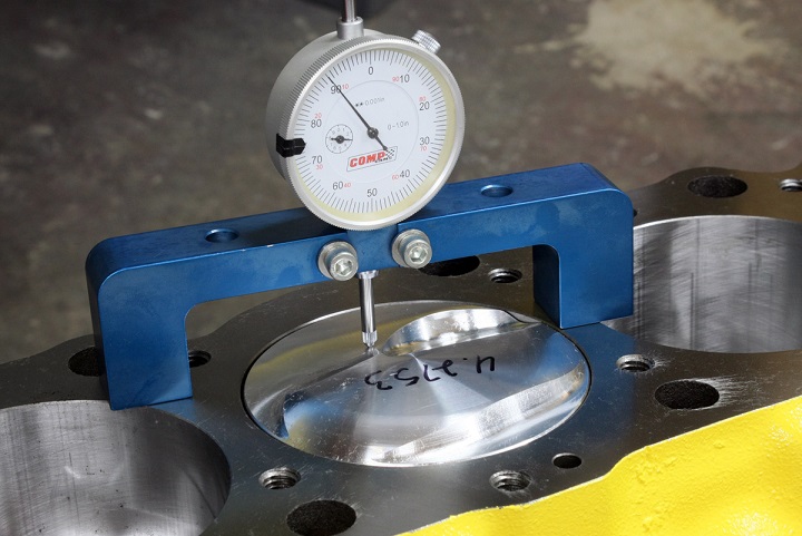
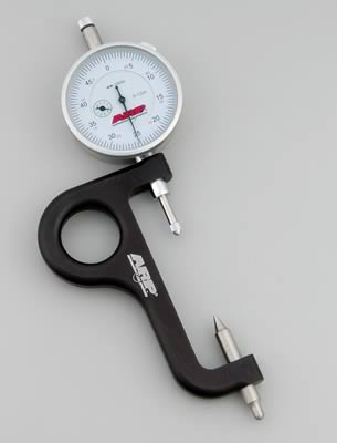
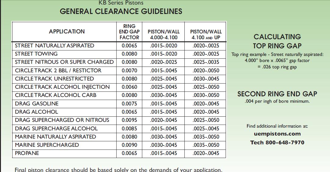
VERIFYING CLEARANCES GREATLY REDUCES WEAR AND DURABILITY ISSUES
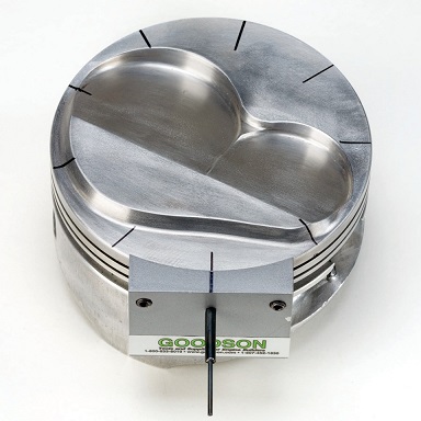
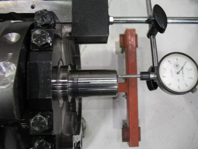
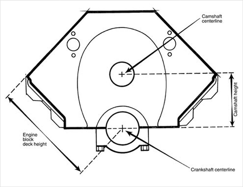
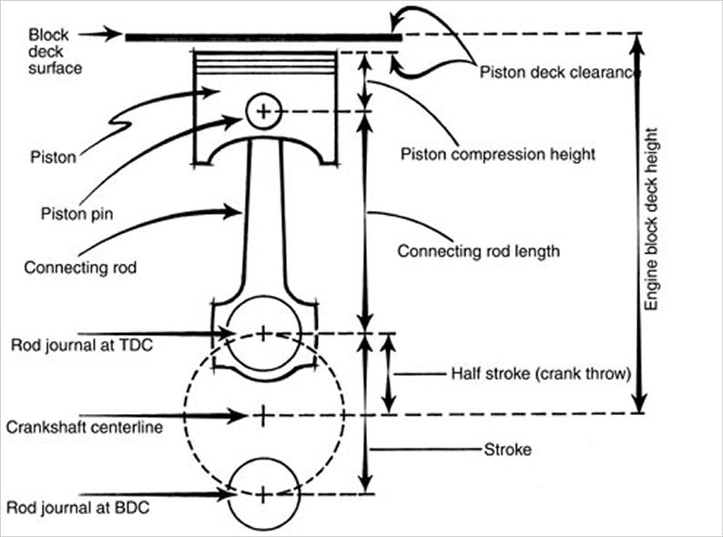
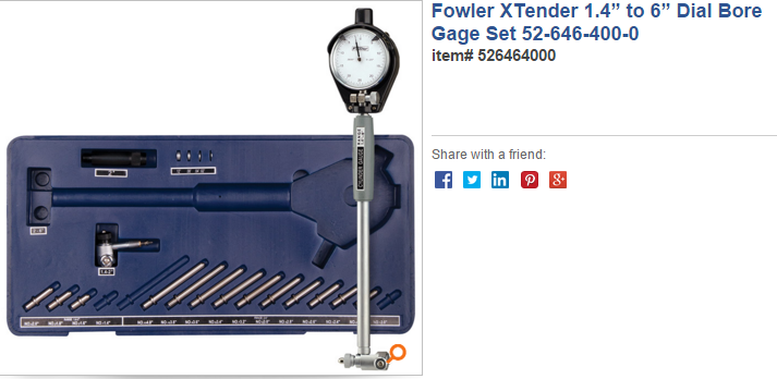
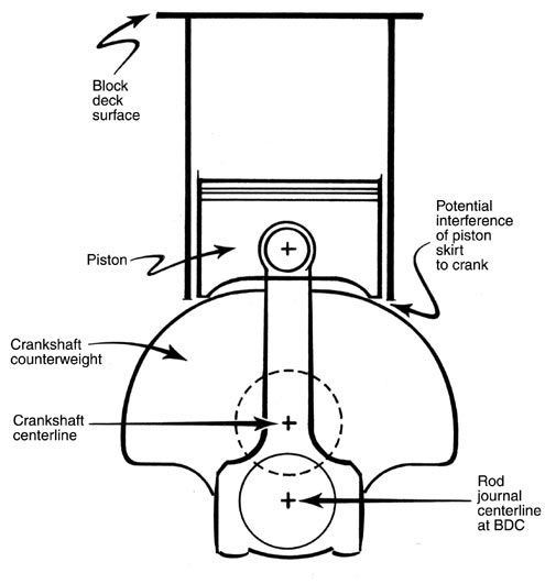
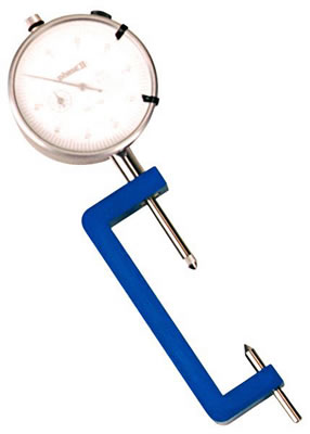
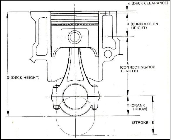
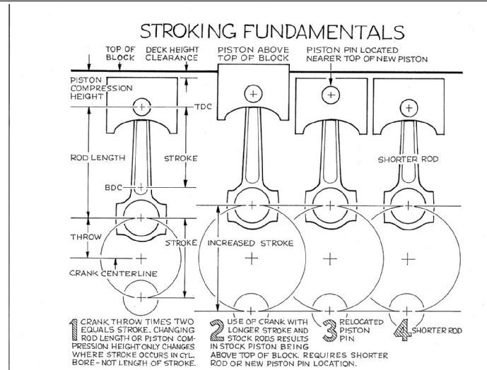
it should be rather obvious that youll need to know the exact distance the piston deck sits at TDC ,above or below the block deck surface and the valve notch recess or pop-up dome volume of the piston to do accurate quench or compression calculations
http://www.harborfreight.com/1-inch-tra ... r-623.html
http://www.summitracing.com/parts/arp-1 ... /overview/ $248
http://www.summitracing.com/parts/arp-1 ... /overview/ $186
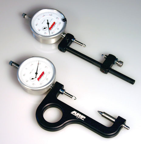
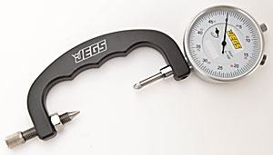
yes you can find non-name brand rod bolt stretch gauges from about $50-$80
https://www.enginelabs.com/engine-t...easuring-rod-bolt-stretch-vs-torque-with-arp/
http://www.performanceenginetech.com/connecting-rod-bolts-stretch-vs-torque/
https://www.hotrod.com/articles/using-rod-bolt-stretch-tool/
http://www.superchevy.com/how-to/engines-drivetrain/49258-rod-bolt-torquing-stretch-info/
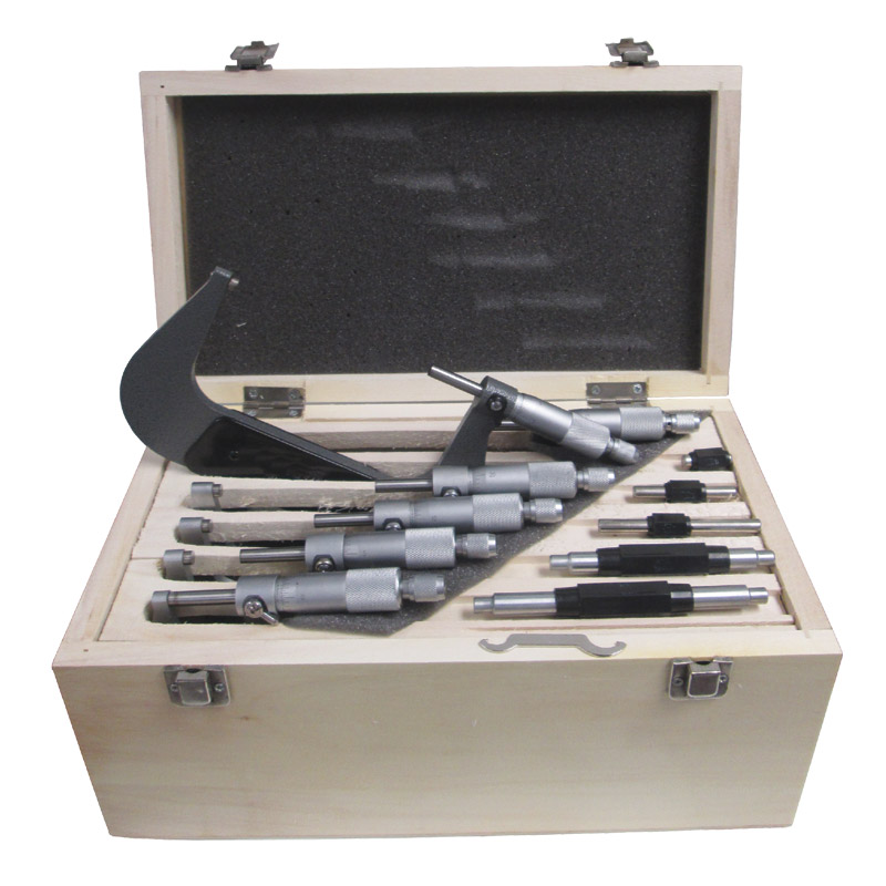
https://ecatalog.mitutoyo.com/Spindle-Attachment-Tip-C1129.aspx
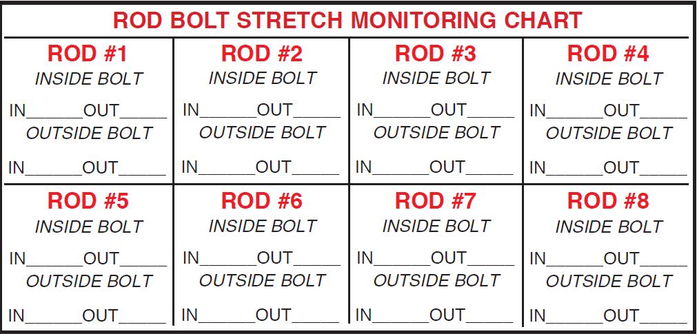
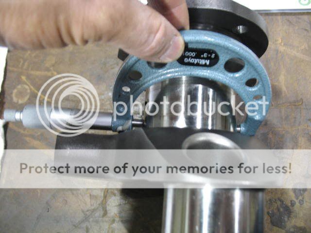
ARP rod bolts are set up to use a stretch gauge with both ends of the bolt pre-machined for the gauge the bolt packaging from ARP,comes with the correct length the bolts are supposed to reach under the correct pre-load tension, in the instructions OR its available on their web site
most guys are familiar with use of a torque wrench to tighten rod bolts to the correct preload, but while this gets you very close its not as precise as a rod bolt stretch gauge,
having consistent clamp loads are mandatory for proper assembly
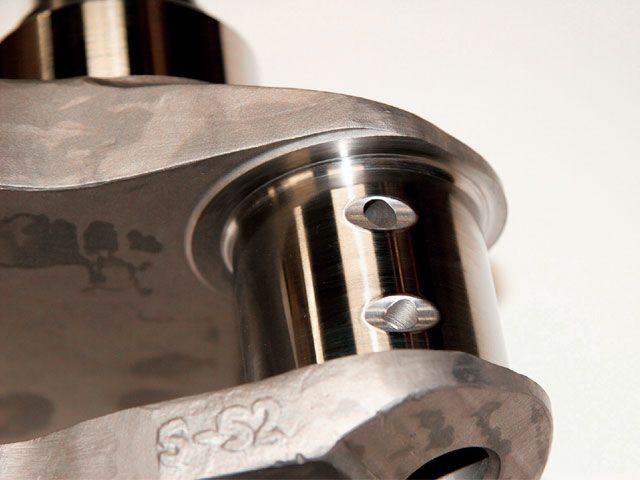
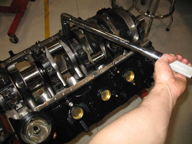
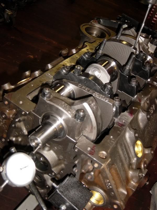
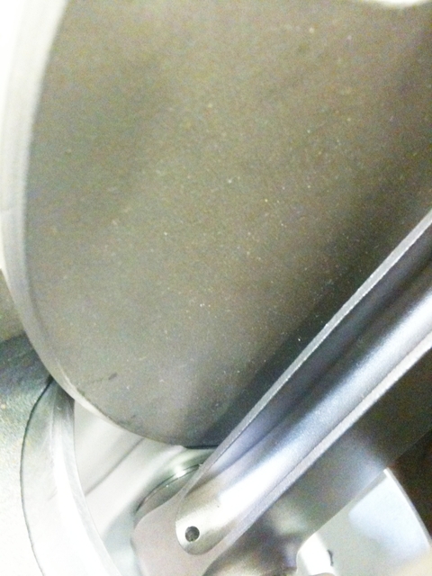
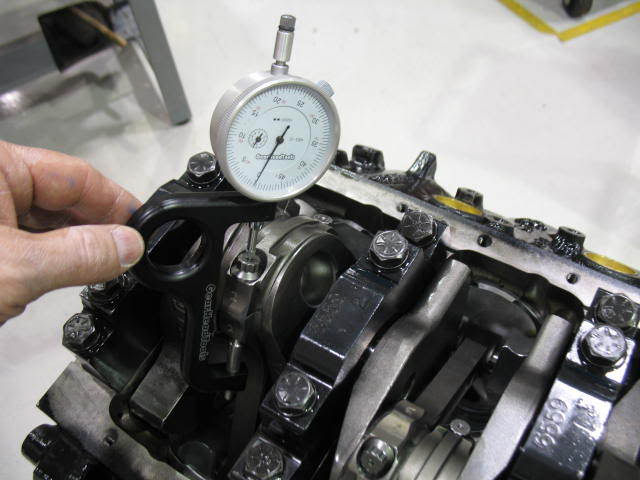
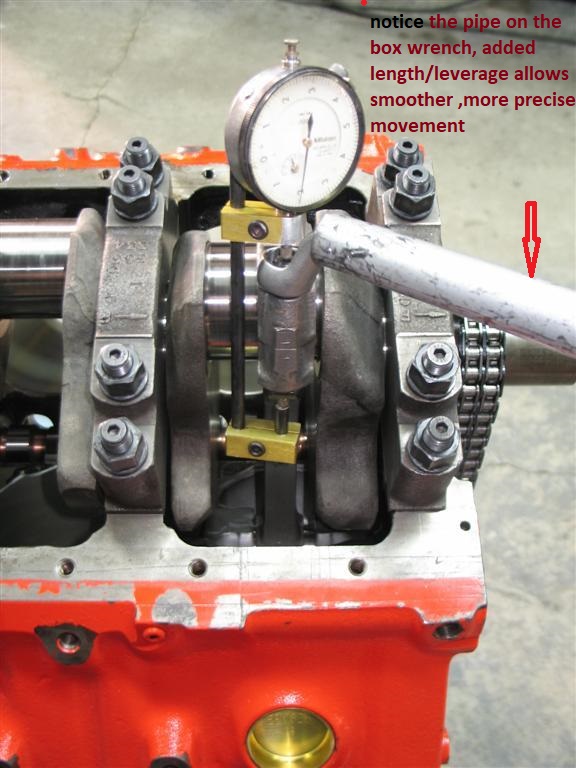
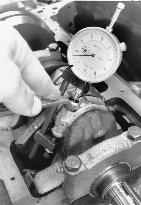
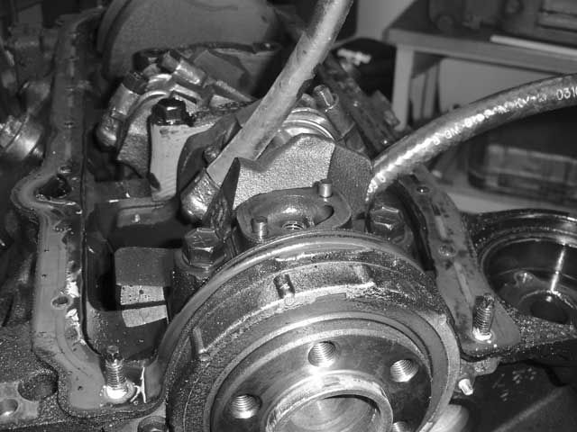
notice how the rod bolts come close to the cam bearings and cam lobes, as the pistons reach top dead canter in the bores, this clearance must be individually checked and should be no less than about .060 (generally you cam use a LARGE plastic tie-wrap
https://www.amazon.com/BuyCableTies...D=41U9CtmwOuL&preST=_SY300_QL70_&dpSrc=detail
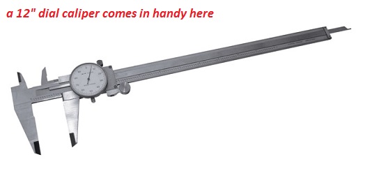
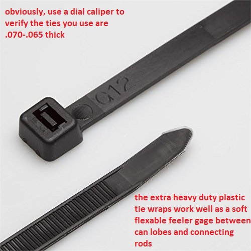
placed between the cam lobe and connecting rod bolts or connecting rod shoulder areas to check clearances as the soft tie-wrap will not damage the cam lobe while you verify clearances)you must install the timing set and index the cam correctly to get a valid clearance , as the cam lobes rotate and at some point they can be incorrectly indexed too hit the rods, while they would not if correctly timed.
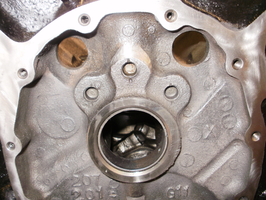
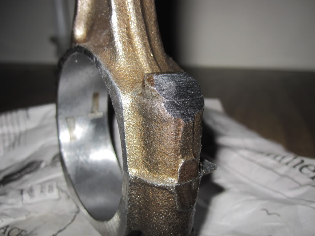
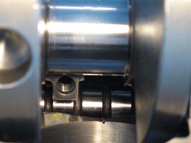
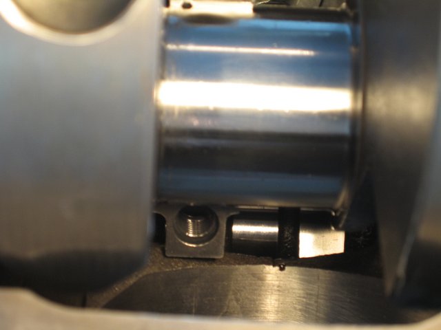
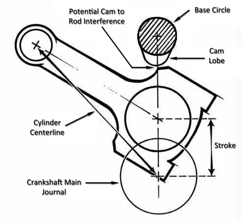
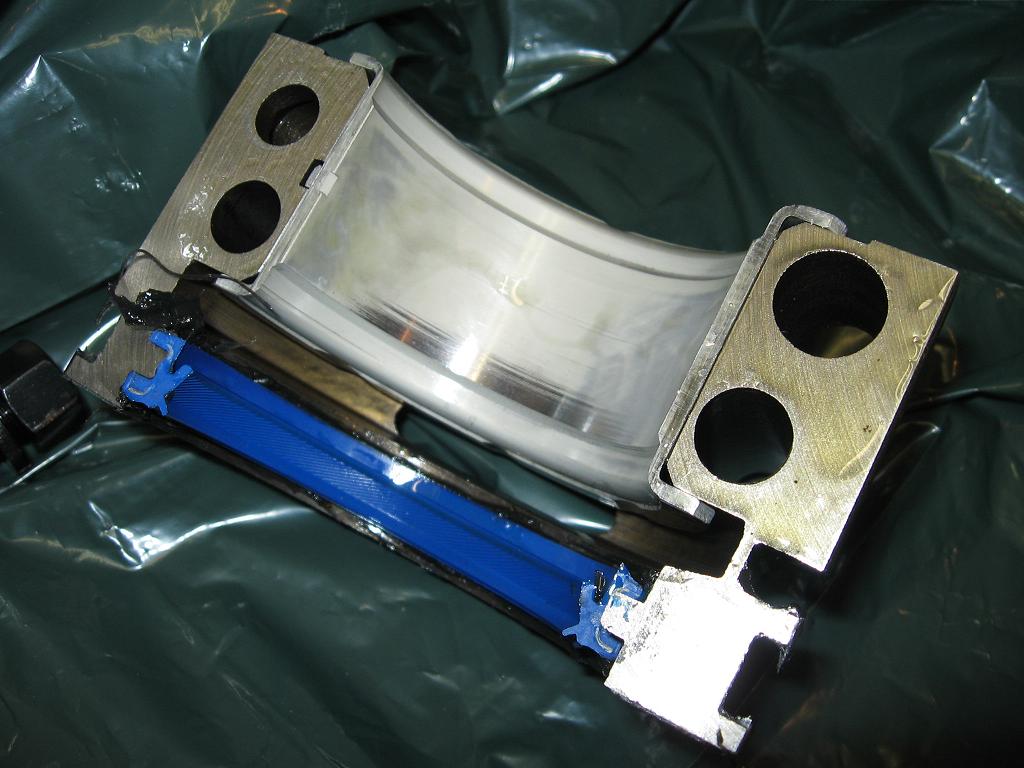
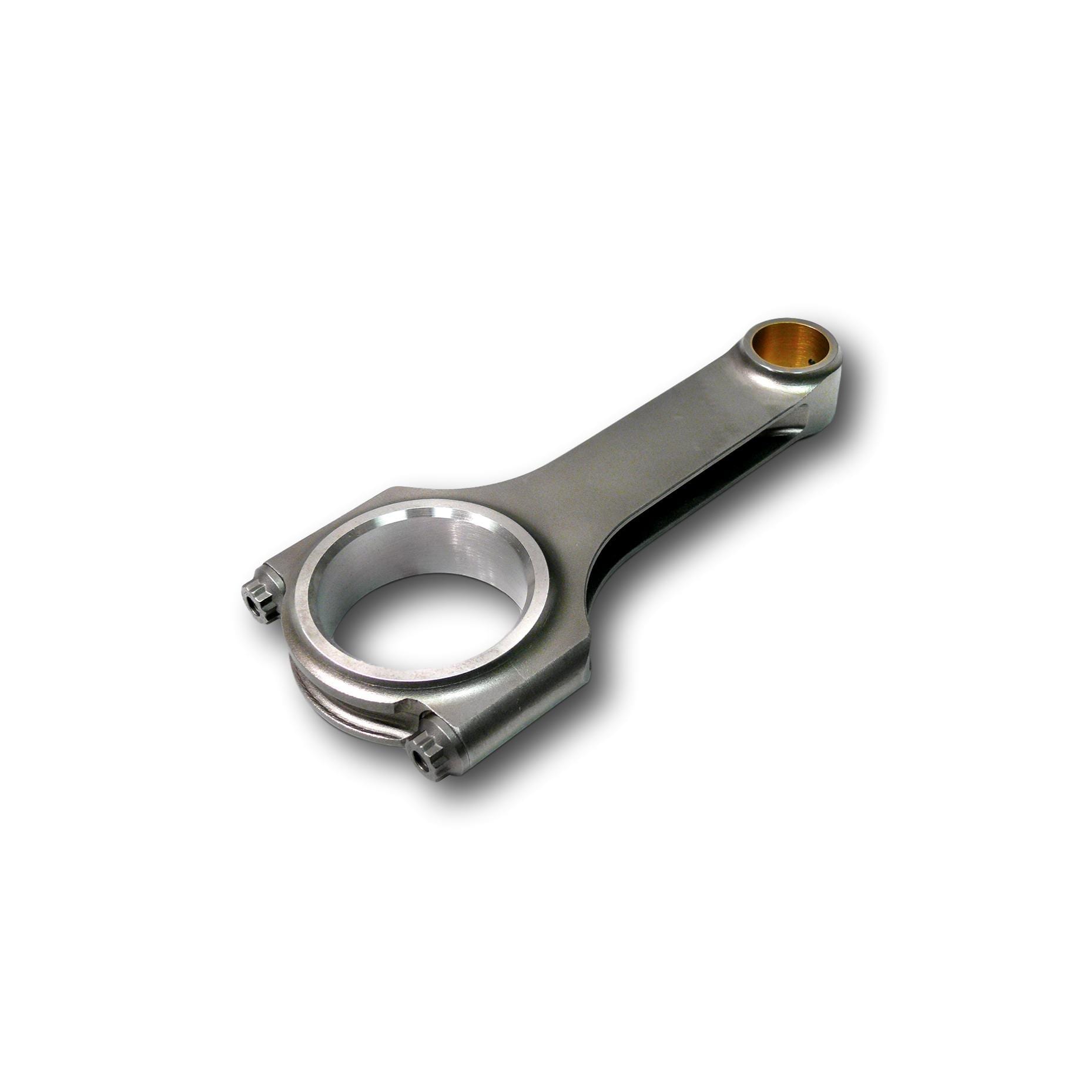
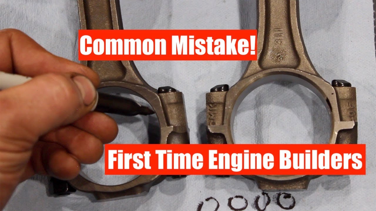
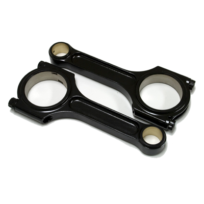
if you wonder why I suggest using SCAT (H) beam style cap screw connecting rods vs stock or most (I) beam designs this picture should show the increased cam to connecting rod clearance.
don,t assume anything! when you assemble the connecting rods and pistons there is ALWAYS some minor differences in dimensions,in piston pin height and rod length, VERIFY QUENCH DISTANCE TO THE BLOCK DECK, so youll want too, try to match the slightly shorter rods to the pistons with taller pin locations so the average quench distances is a bit more consistent
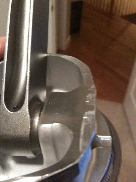
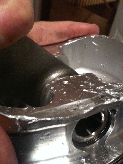
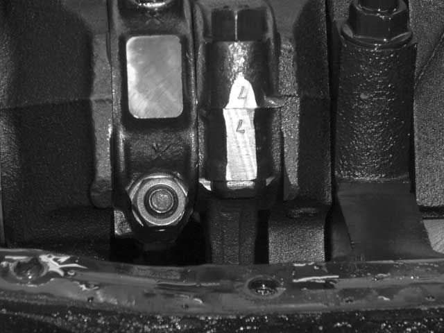
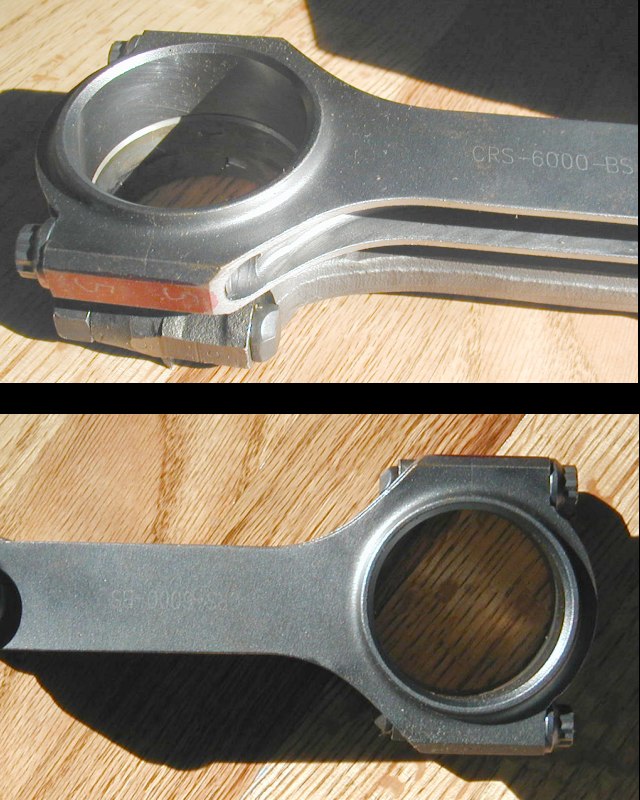
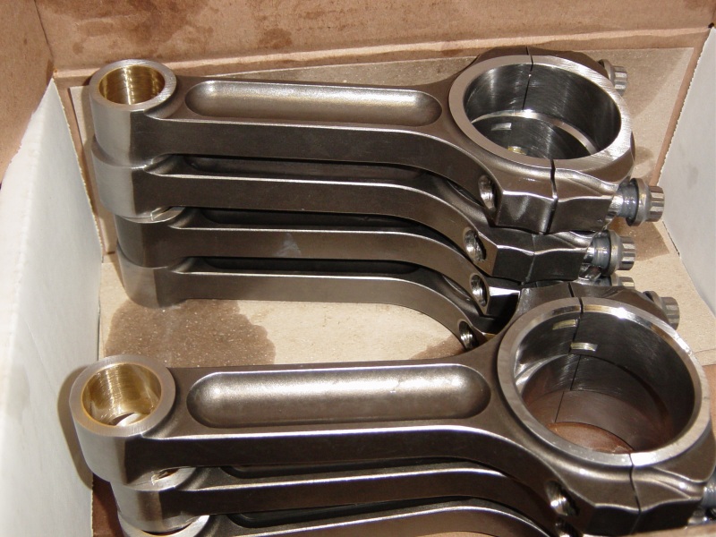
one factor to keep in mind is that rods typically have a side that rides against its matched companion and a side thats BEVELED for clearance on the crank journals radias EXAMPLE

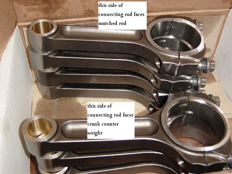
notice the top rods non-beveled side that faces the matching rod is up, but on the lower rod the the beveled side that faces the crank counter weight is up on the lower rod
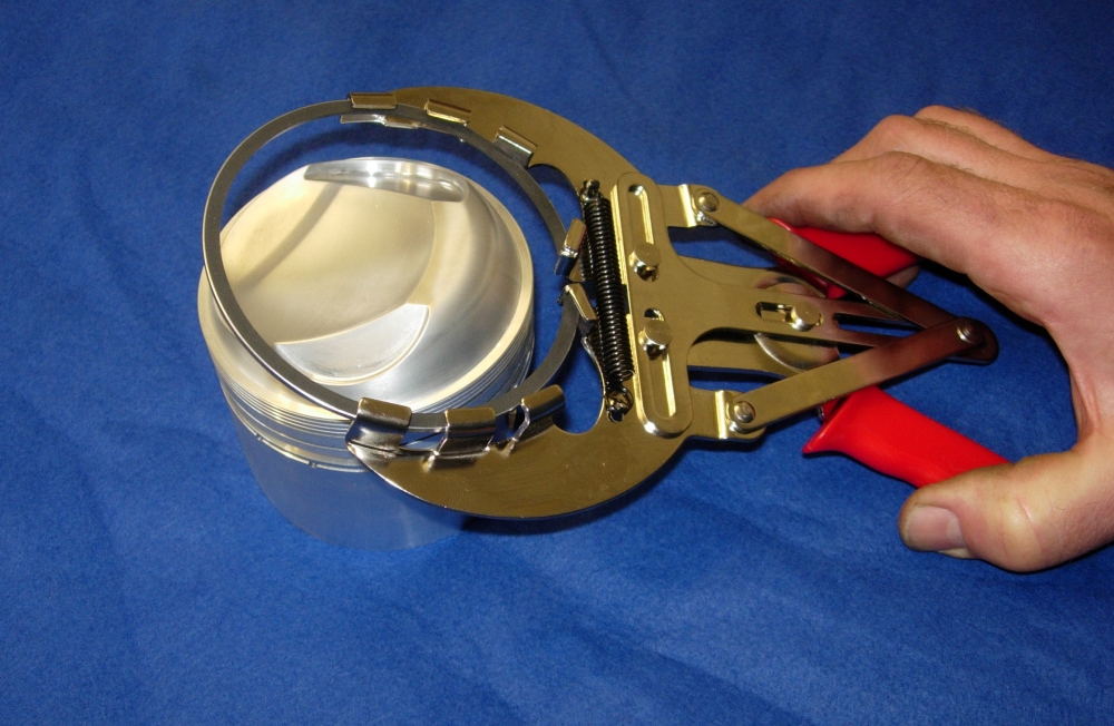
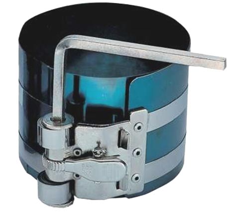
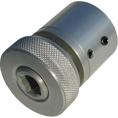
the 80MM-120MM tool fits all chevy V8 engines
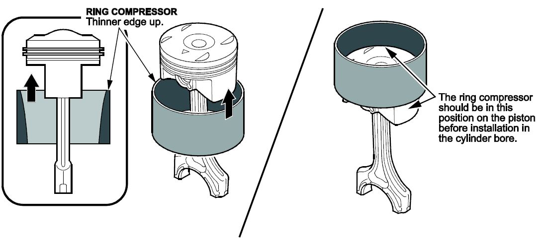
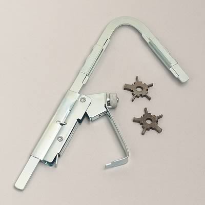
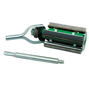
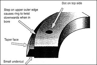
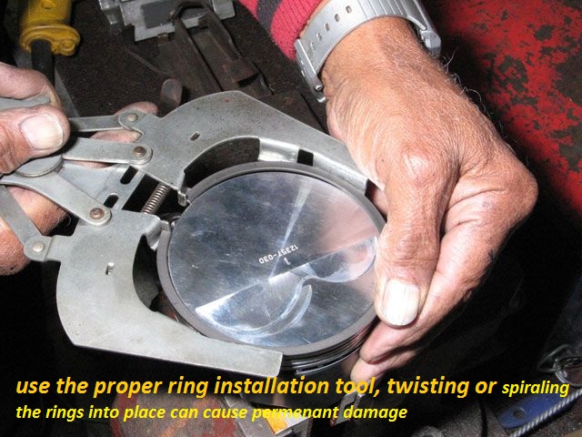
BTW I recommend THIS TYPE of piston ring compressor (below)as the type in the video can and occasionally does allow the rings to pop out and jam, or break far more frequently .
the picture lacks detail, but the interior of the compressors tapered, you tighten to a slide fit on the piston diam. and the rings compress fully as they are entering the cylinder entrance and only expand after entering the bore.
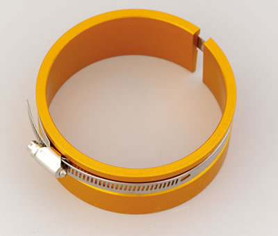
BTW when you go to buy a ring compressor....this type works far better than the others
http://store.summitracing.com/partdetail.asp?autofilter=1&part=PRO-66766&N=700+115&autoview=sku
Proform 66766 $31
http://garage.grumpysperformance.co...ng-piston-pin-height-compression-height.5064/
http://garage.grumpysperformance.co...n-wrist-pins-one-really-over-looked-part.978/
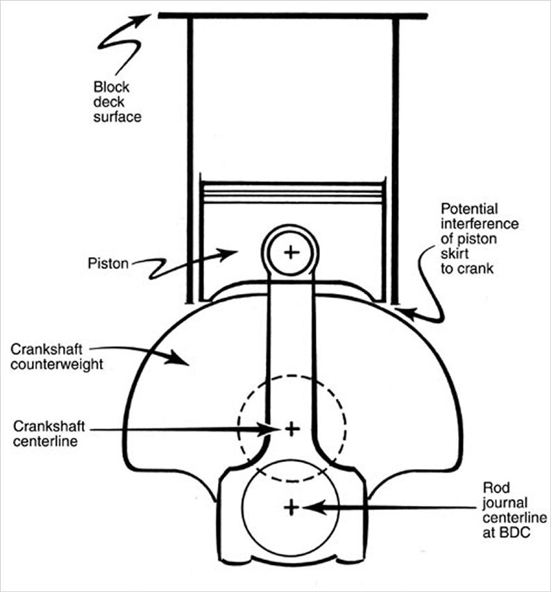
if you find the rotating assembly is more difficult to rotate than you expected, you may want to verify some clearance issues that get over looked at times,
theres also some, other potential issues,
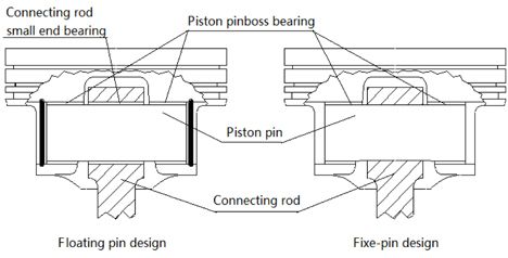
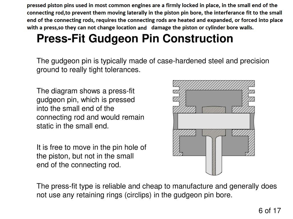
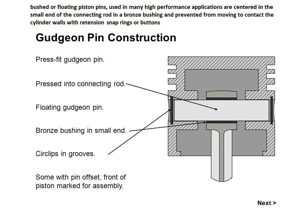
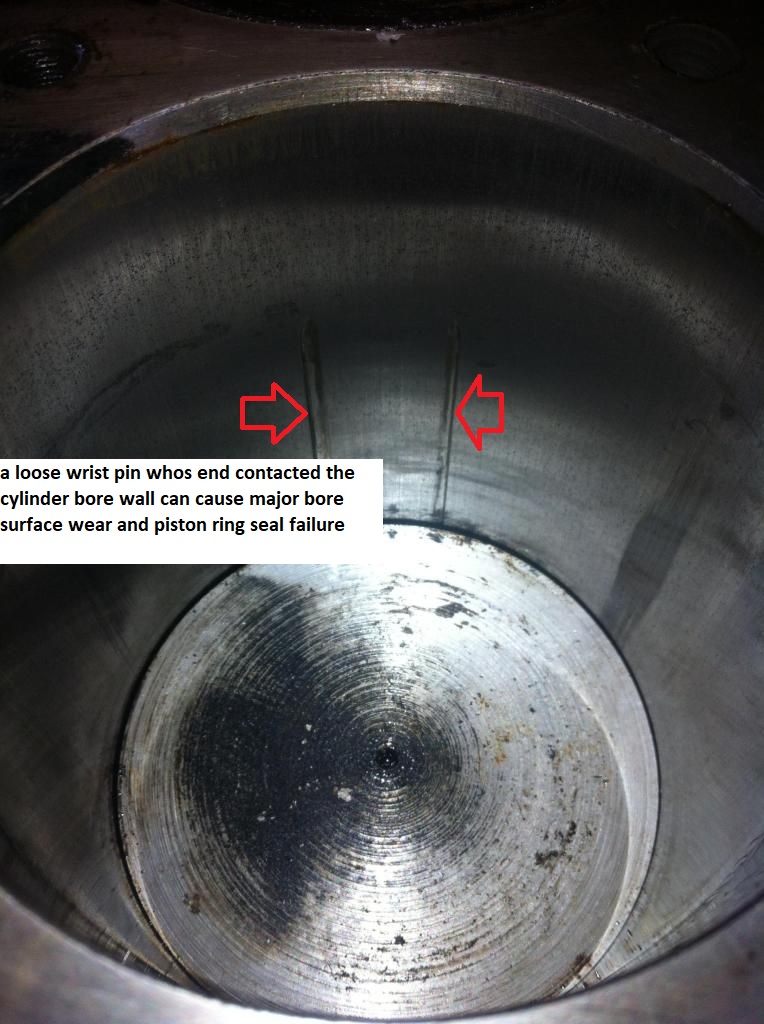
theres a slight potential for the piston wrist pins too not rotate effortlessly in the piston pin bores ,
that may add to the difficulty in rotating the assembly in the block.
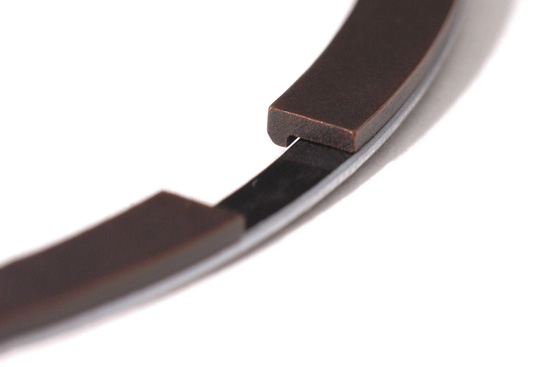
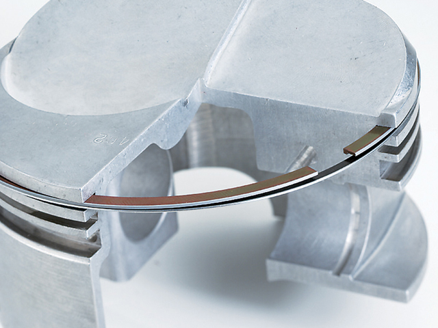
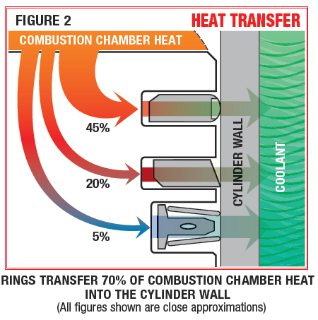
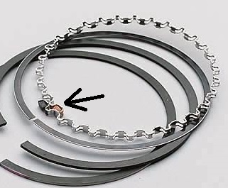
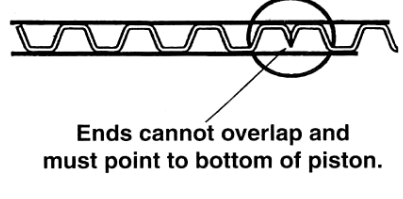
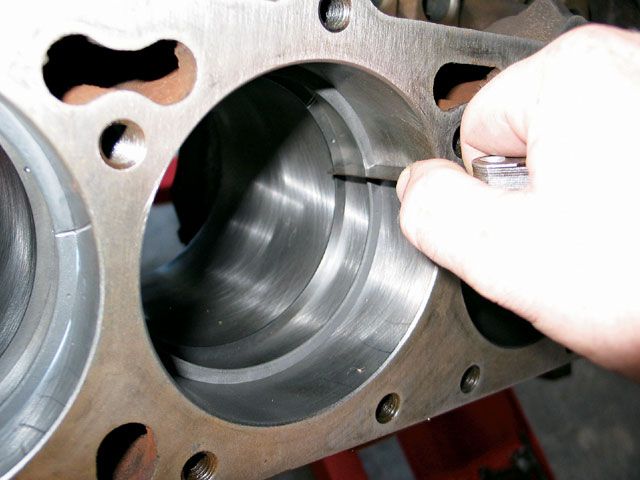
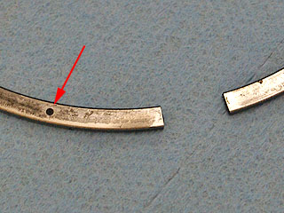
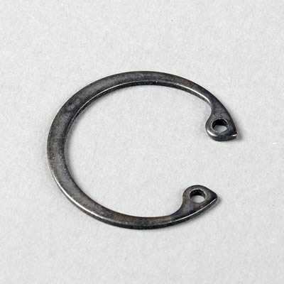
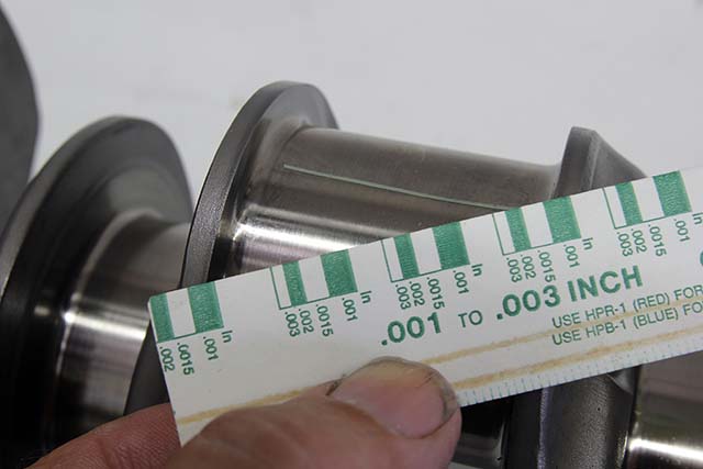
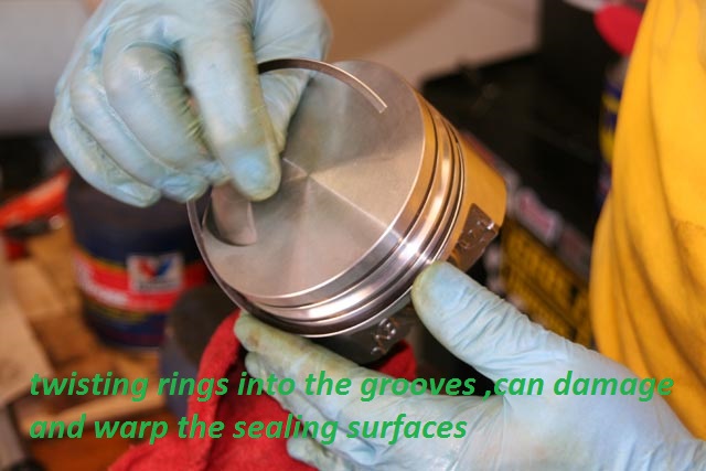
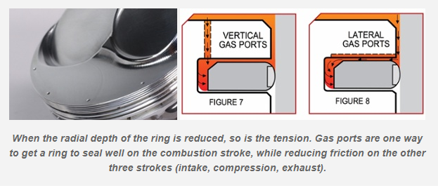
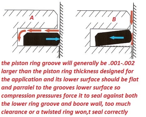
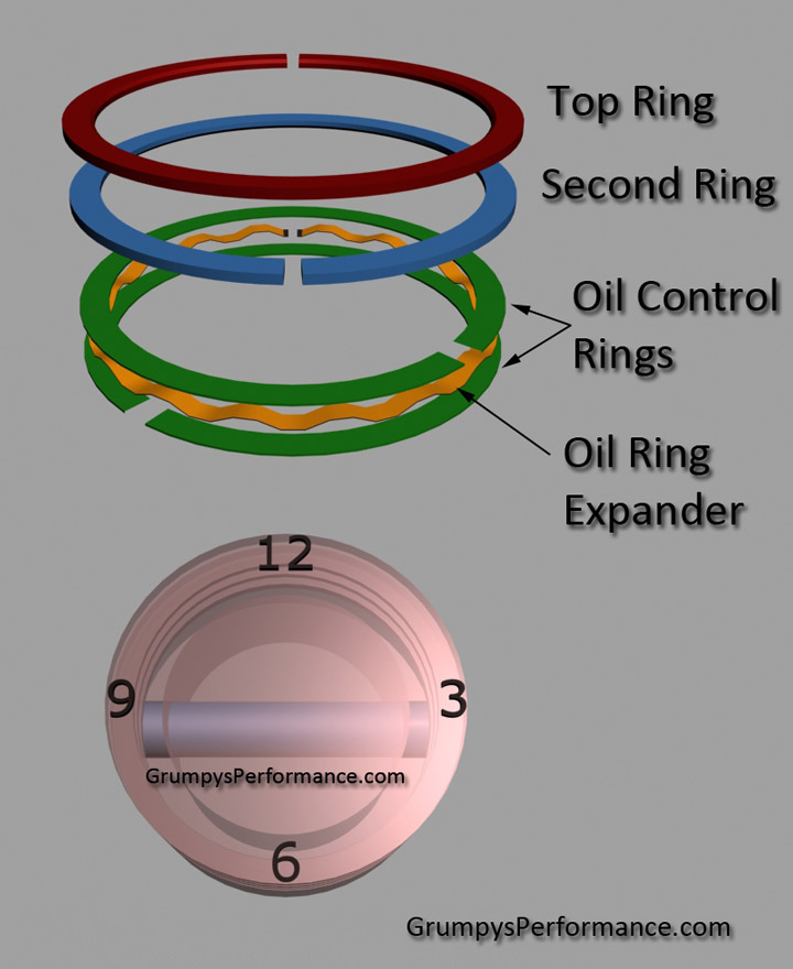
the piston rings must have vertical and back clearance in the piston ring grooves
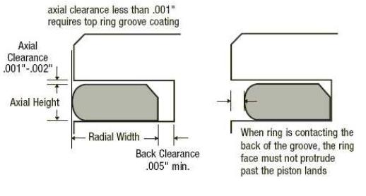
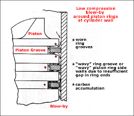

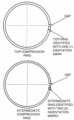
Piston Ring Groove Clearance
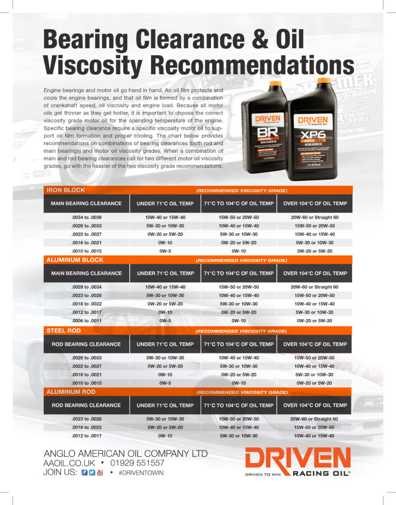
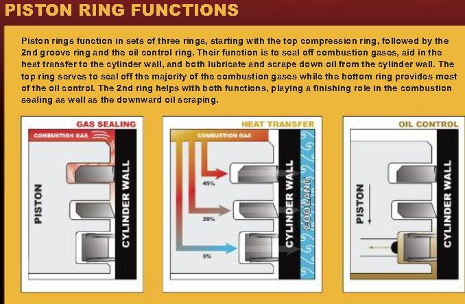
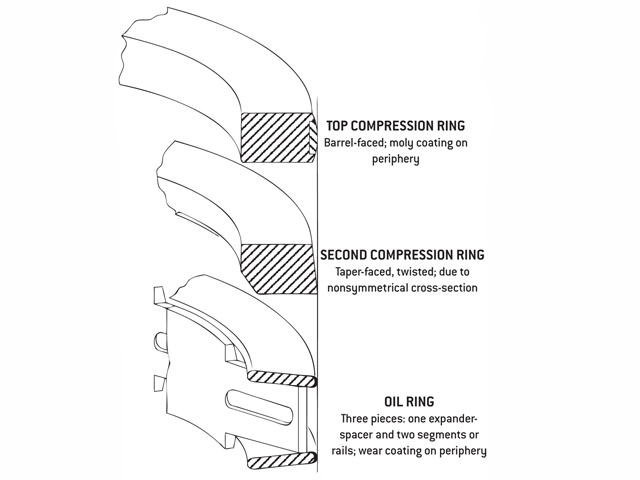
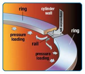
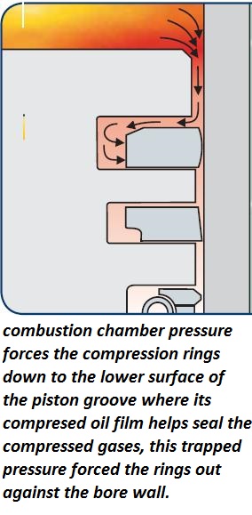
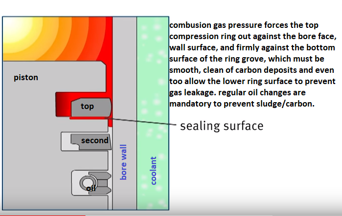
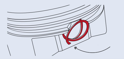
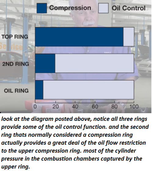
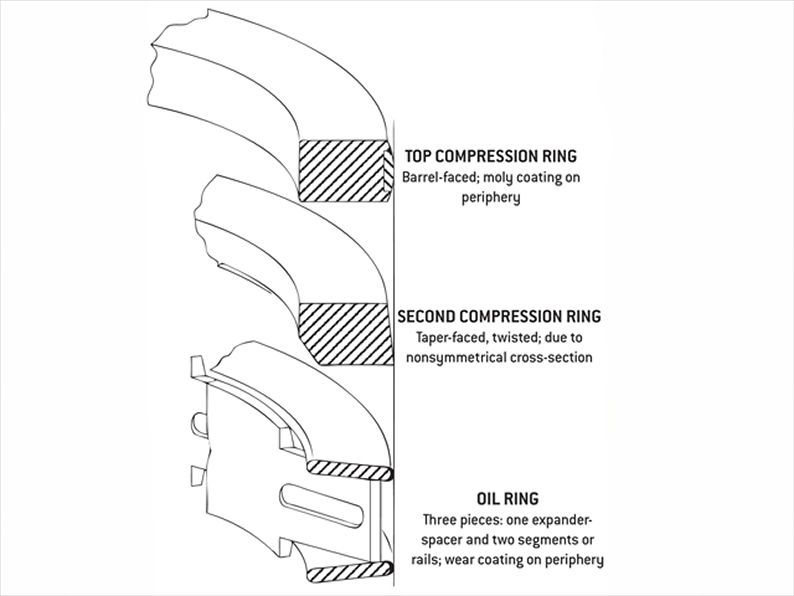
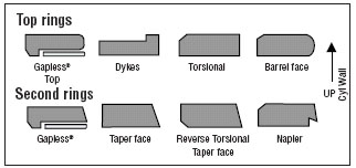
Pistons are grooved to fit rings that seal the cylinder’s compression and allow for lubrication of the cylinder walls. Piston rings come in a set. There are two compression rings. The top ring is affected by the most cylinder compression pressures. The second compression ring reinforces the top ring. The third ring down is the oil ring. It controls lubrication between the piston and cylinder bore.
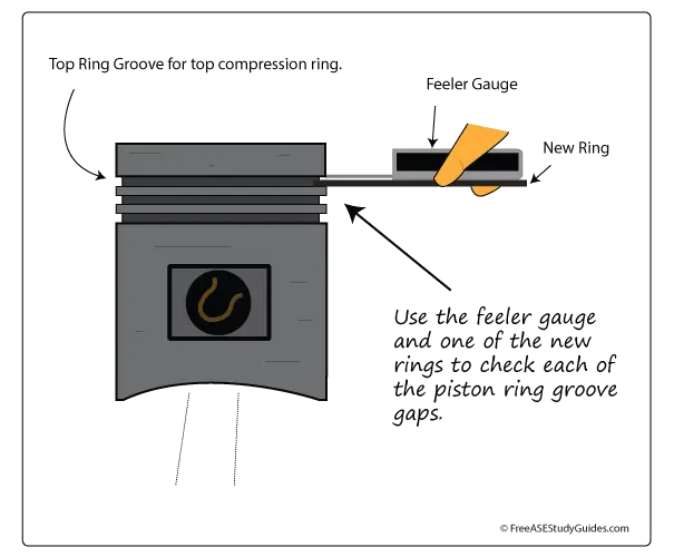
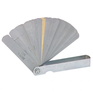
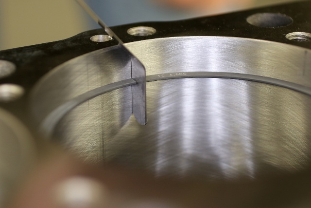
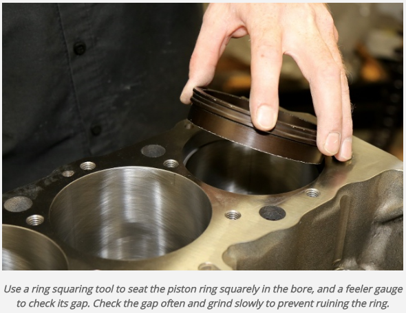
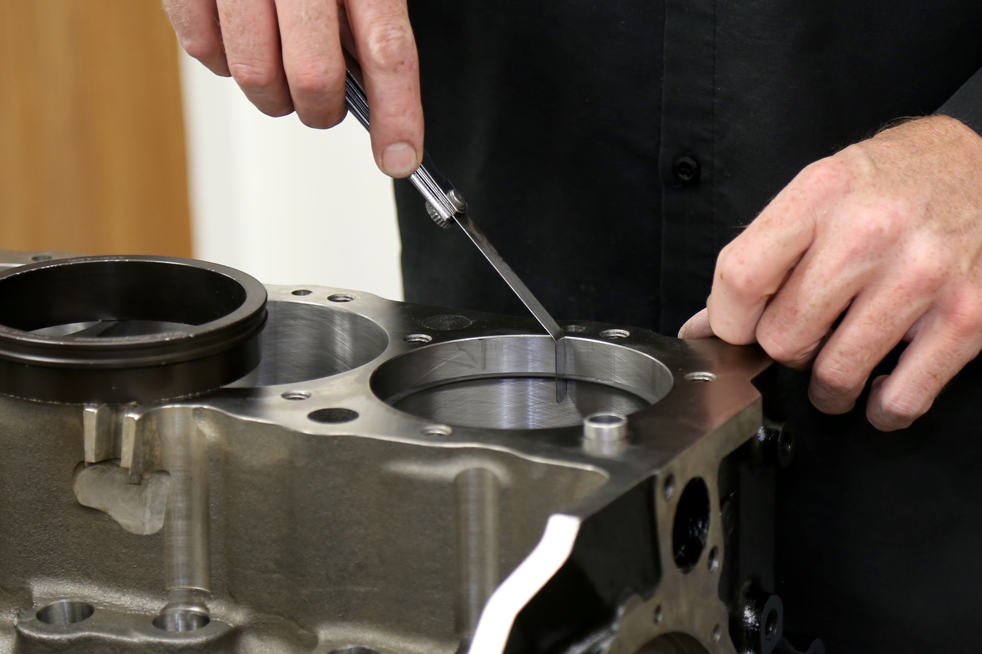
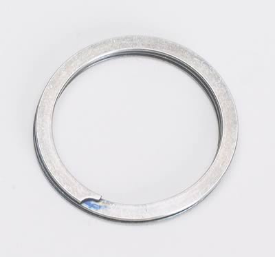
Place the new ring into the top piston groove, and then place a feeler gauge into the gap between the new ring and the upper land. Move around the pistons groove and obtain a few measurements. Compare this reading to specifications. If this reading is too much and the gap is too large, the piston must be replaced. The top ring takes the most compression. This causes the ring to slap against and wear the lands in the piston groove.
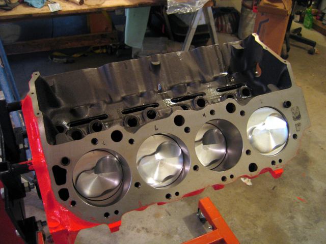
and of course the pistons must have the correct piston too bore clearance. and connecting rod can only be installed facing one direction

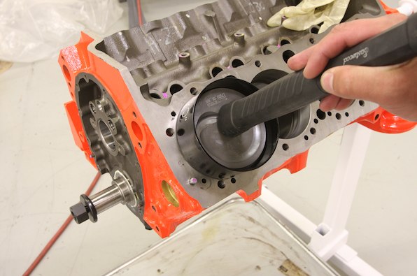
youll be surprised at how much easier they slide into the bore if you BOTH pull/guide and push the pistons into the cylinders rather than just beat them in with a hammer handle, it takes some practice but a few taps to get them moving with a fist, while pulling and guiding the rod into its journal is usually all that necessary with a well oiled piston and that type of ring compressor.
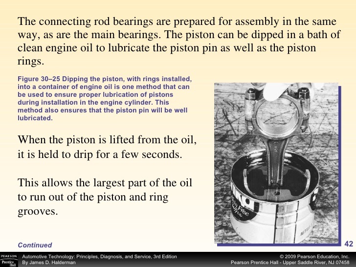
IVE dunked my piston/ring assembly's in a can of MARVEL MYSTERY OIL just before installation with a ring compressor and have never seen the slightest indication of problems either on ring sealing getting the rings broken in, or on tearing the engines down later for inspections
KEEP IN MIND
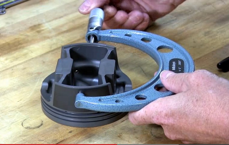
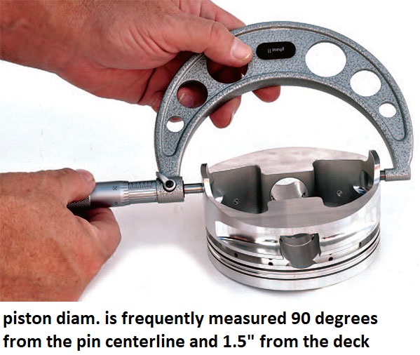
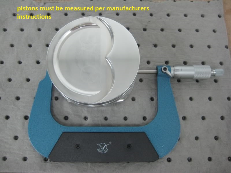
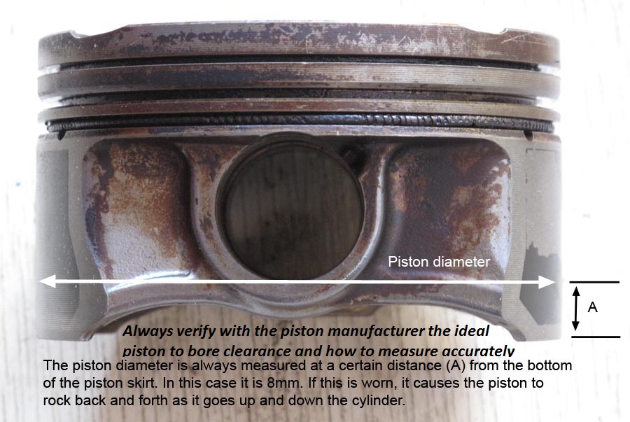
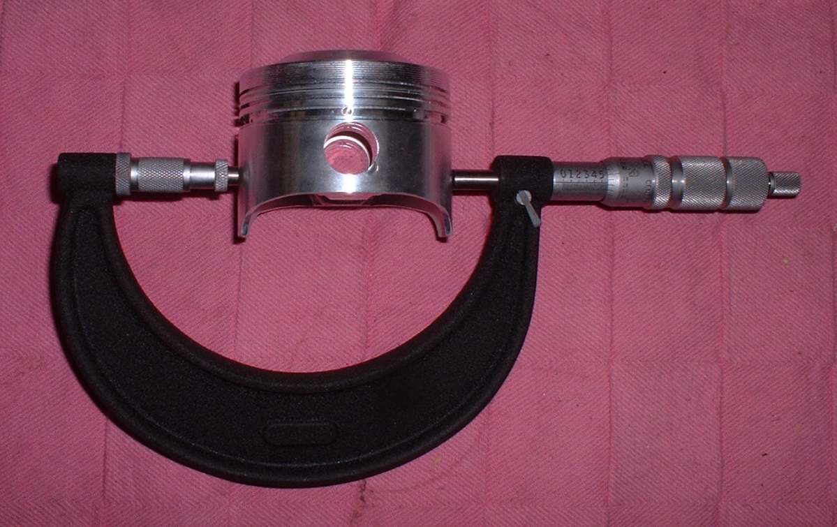
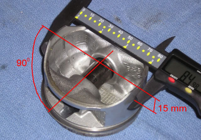
be sure you, measure EACH bore and EACH piston,
(CORRECTLY with the proper tools in the way the tool and piston manufacturers suggested)
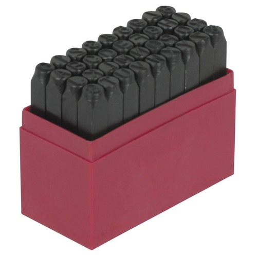
and number them on an engine build sheet indicating the bore and piston diam.
from large to smallest on each and install them on each cylinder to get the most consistent piston to bore clearance's
yes the difference may only be a few ten thousands if the bores are machined correctly, but you'll get the best results , most consistent lubrication, best durability and less heat build up that might result in detonation issues that way. its the little things that add up to making a good durable engine assembly,
BTW check rod orientation, so the beveled sides don't fact the adjacent rods, and check the bearing clearances with plasti guage
garage.grumpysperformance.com
garage.grumpysperformance.com
garage.grumpysperformance.com
garage.grumpysperformance.com
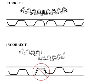
any ring compressor design you use regardless ,of the design MUST have its lower surface kept firmly in contact with the block surface and parallel to the bore to allow the rings to smoothly transition from the inner surface of the compressor to the blocks bore, and IDEALLY the compressor internal diameter will be marginally smaller in internal diameter that the cylinder bore the pistons sliding into from it!
http://www.engineprofessional.com/TB/EPQ410_10-18.pdf

FOR YOUR OWN GOOD< READ THE SUB LINKED INFO
http://www.kb-silvolite.com/assets/kb_installation.pdf
http://www.connectingrods.net/connectin ... tretch.php
http://www.enginebuildermag.com/Item/38 ... rings.aspx
https://www.uempistons.com/installation ... lation.pdf
when in doubt call the PISTON manufacturer and ASK!
http://www.circletrack.com/enginetech/c ... ce_basics/
http://www.stockcarracing.com/techartic ... index.html
http://www.circletrack.com/howto/1815_c ... to_04.html
http://arrc.epnet.com/autoapp/9102/9102 ... SEMBL1.htm
http://www.corvette-restoration.com/res ... lation.htm
http://www.popularhotrodding.com/engine ... index.html
http://www.pawengineparts.com/shoppingc ... ?catid=206
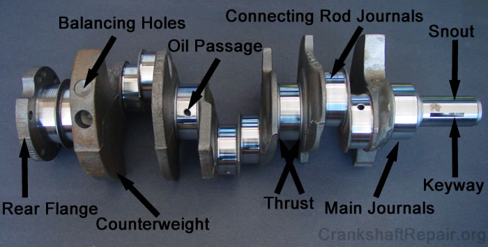
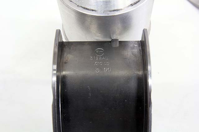
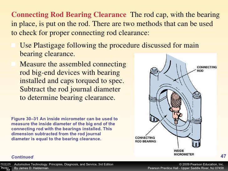
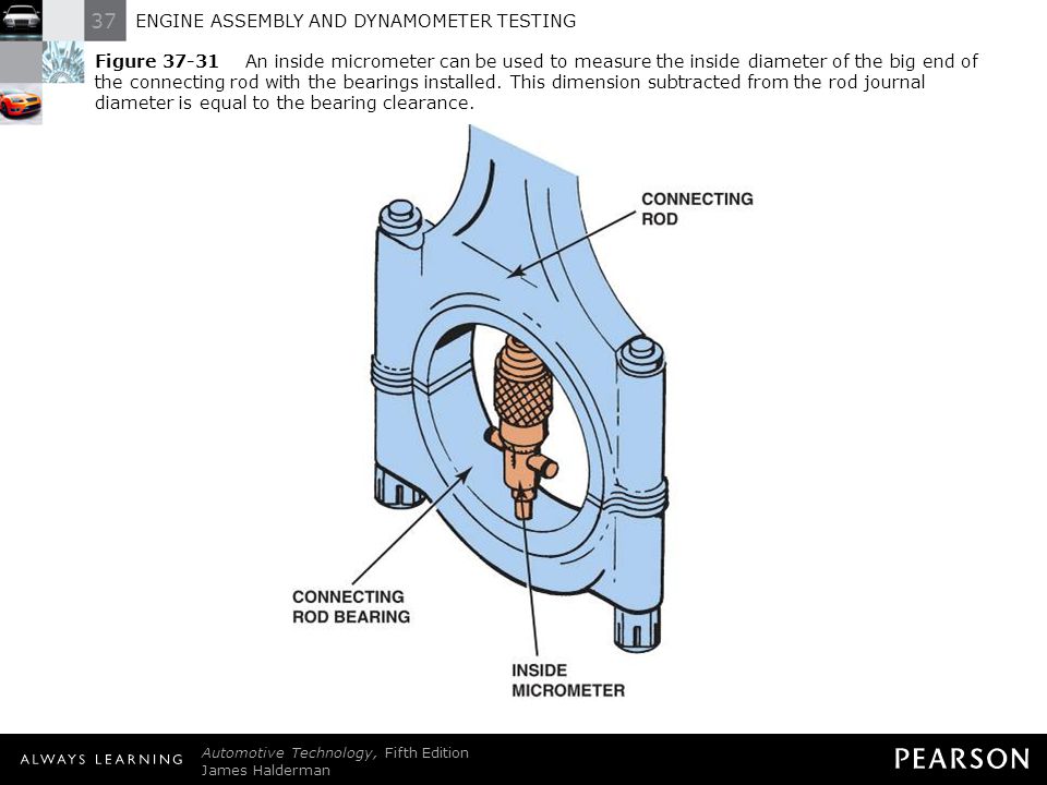
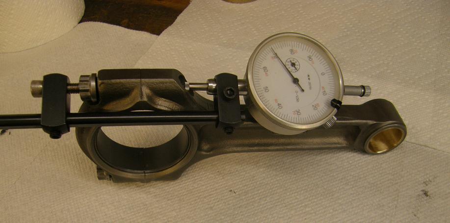
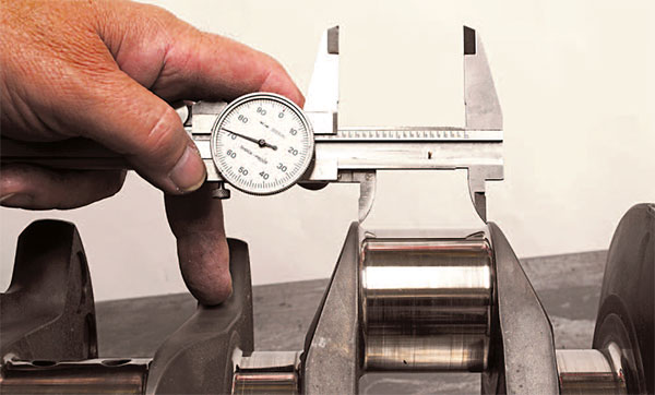
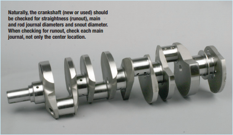
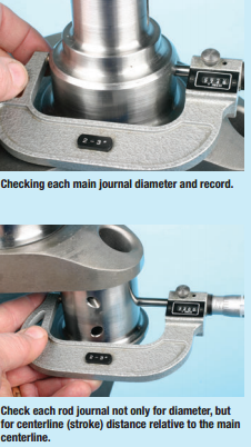
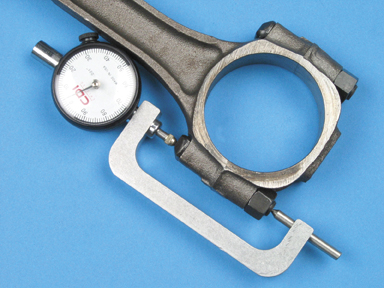
naturally youll measure the bearing journals
one factor to keep in mind is that rods typically have a side that rides against its matched companion and a side thats BEVELED for clearance on the crank journals radias EXAMPLE
notice the top rods non-beveled side that faces the matching rod is up, but on the lower rod the the beveled side that faces the crank counter weight is up on the lower rod
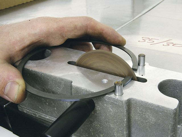
rod-grinding
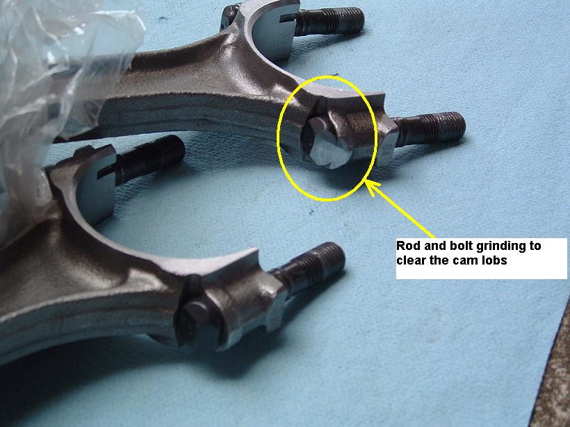
on some stroker applications SOME rods need to have the bolts ground for cam lobe clearance
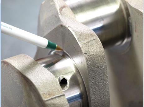
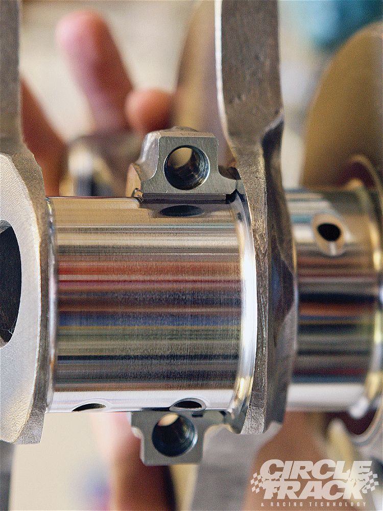
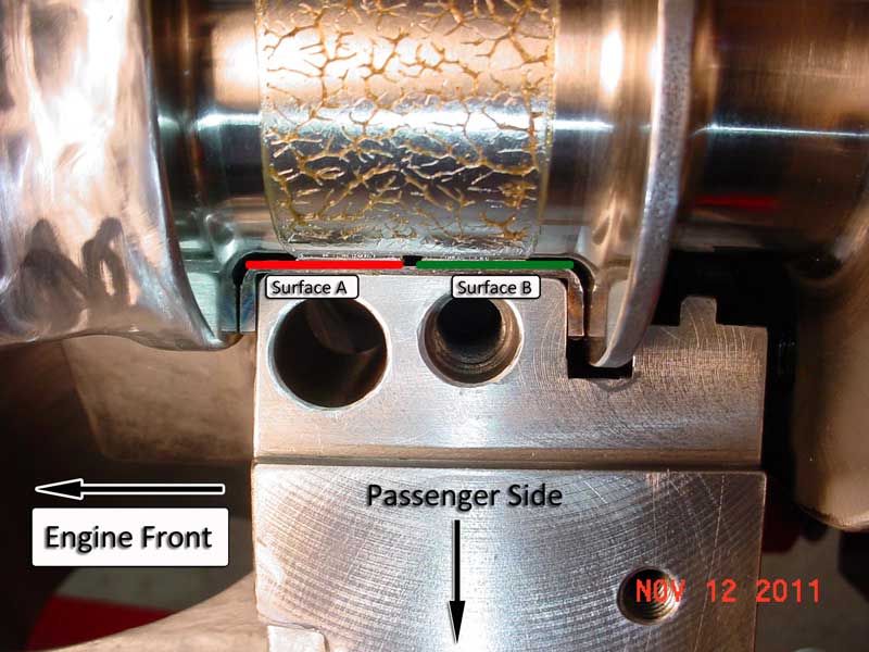
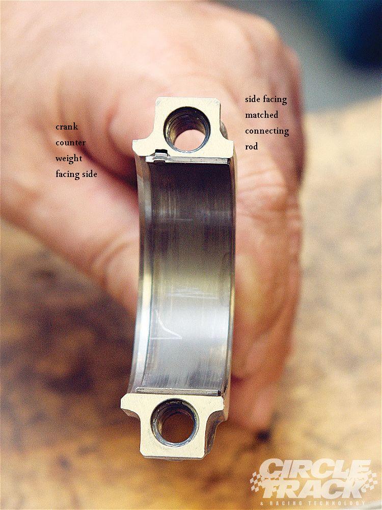
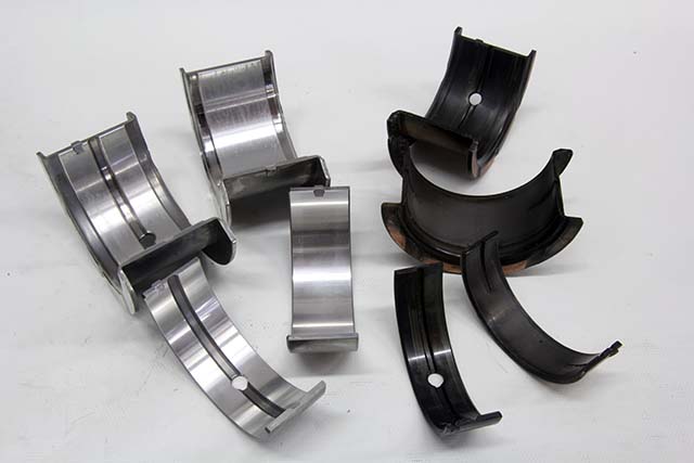
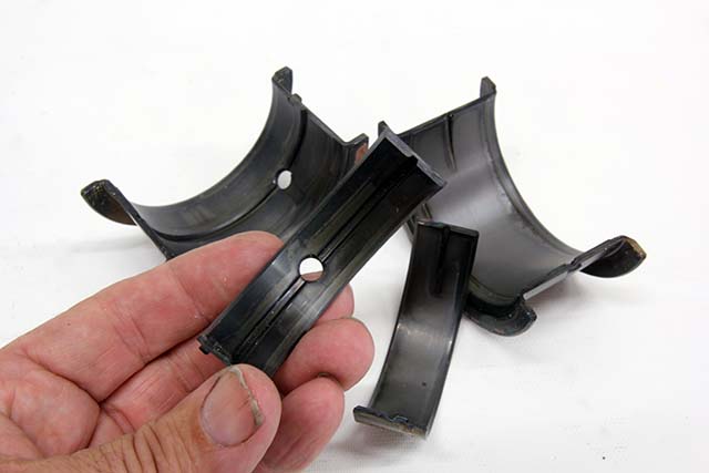
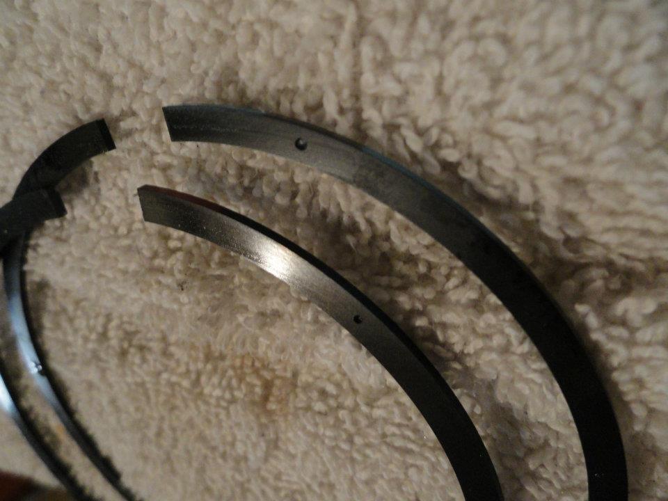
bearings AND connecting rods have an inner facing side and outer side the inner side facing the matching rod has far less edge clearance because they don,t need the radias that is required for the edge of the crank journals

notice the top rods non-beveled side that faces the matching rod is up, but on the lower rod the the beveled side that faces the crank counter weight is up on the lower rod
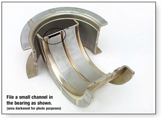
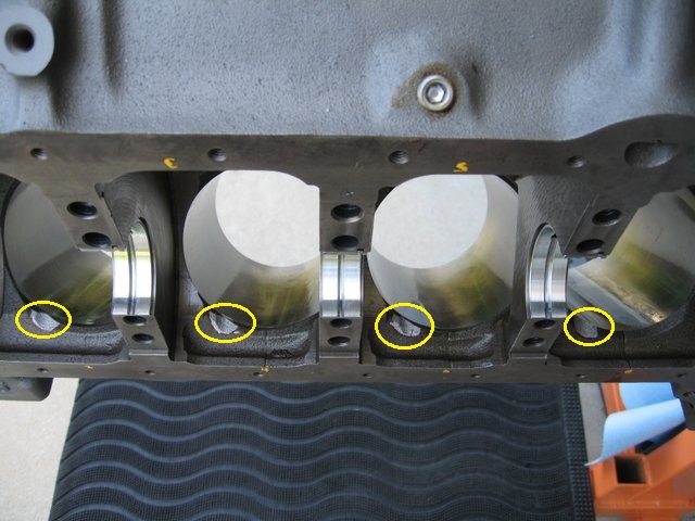
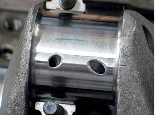
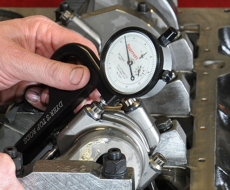
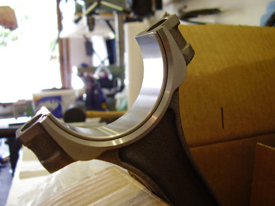
notice how one side of the bearing holding section has a radias (left)(GOES TOWARD CRANK COUNTER WEIGHT) but the opposite sides flush (right) (FACES MATCHED ROD)
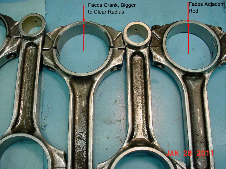
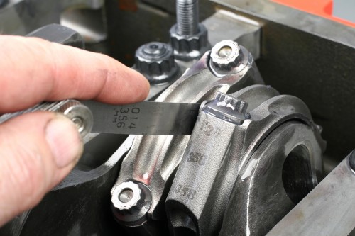
ok lets look at a few things, first , if you look closely at your connecting rods you'll see that one side has considerably more bevel ground on the inner edge of the connecting rod around the bearing than the other side does, to side with that bevel ground on it is to provide clearance for the radius ground onto the crankshaft where the crank throw meets the counterweights like you mentioned, that side of course goes out away from the other rod, to side with far less pronounced bevel is the side where the two connecting rods meet, and ride against each other during normal engine operation normal clearance there is in the area of six to 15 thousands of an inch. When the two connecting rods are correctly torque in place and a feeler gauge is fitted between them to check the maximum clearance.
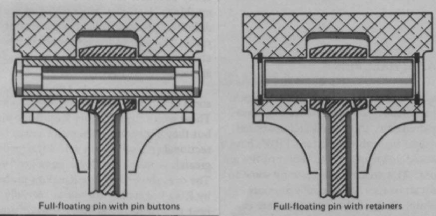
Now a small block Chevrolet the valve placement or valve layout is in this order on a normal head, E I I E E I I E , the letter (E) of course representing exhaust and the letter (I) of course representing intake your Pistons will have to be inserted into the cylinders matching that layout, this will mean there will be two left and two right Pistons on each cylinder bank, if there is a dome on the Pistons it will go towards the outside of the block, when the machine shop installed the Pistons on the connecting rods, they should have been set up with four of the Pistons set up with the exhaust valve notch on the Pistons facing towards the bevel on the connecting rods and four of the Pistons set out live the intake valve side of the Pistons facing that bevel, lets look at the first two cylinders, cylinder number one is the front left forward facing forward look at the diagram per cylinder layout any
on that Piston both the bevel for the Crank Journal that provides bearing clearance and the exhaust valve notch would be towards the front of the engine, but on the next cylinder number two, on the opposite side of the engine. That Piston would have the bevel on the connecting rod facing the rear of the engine, but the exhaust valve notch would be facing the front of the engine, now let's look at cylinders three and four, cylinder number three, would have the bevel on the rod of course facing forward but the exhaust valve notch facing the rear of the engine, on cylinder number four you would have the bevel on the connecting rod facing towards the rear of the engine, and the exhaust valve notch facing towards the rear of the engine, now let's look at cylinders 5 and 6 cylinder number five, bevel forward exhaust forward, cylinder number six exhaust forward but bevel towards the rear for cylinders number 7 & 8 on cylinder number seven, exhaust out notch towards the rear, bearing bevel towards the front of the engine on cylinder number eight bearing bevel towards the rear of the engine and exhaust out towards the rear of the engine
keep in mind that some non- standard head / port layouts can potentially change the piston notch layout
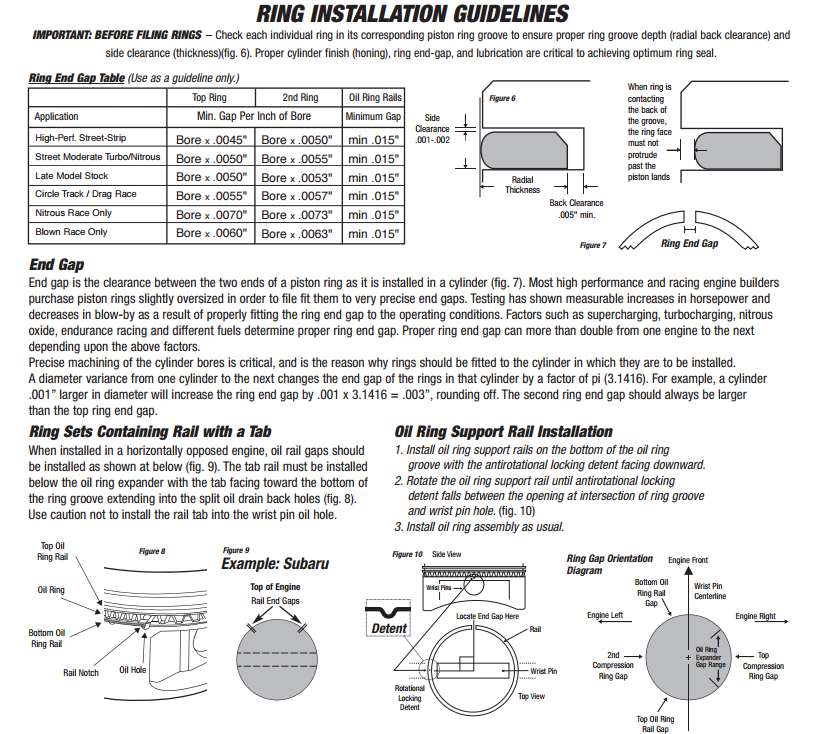
you¢ll also need to make sure youe piston ring end gap is correct, that the piston rings have the correct side facing upwards that the bearings are installed with the correct clearance, and coated with assembly lubricant, that the piston to cylinder block deck clearance is correct ,that your quench distances are correct, and that after you degree in the cam that the piston to valve Clearance is correct. Youll also need to be careful that you don,t hit the connecting rod or rod bolts to the crank journals potentially causing any damage during the installation, and its normal to oil the rings and piston with a lite machine oil during the installation.
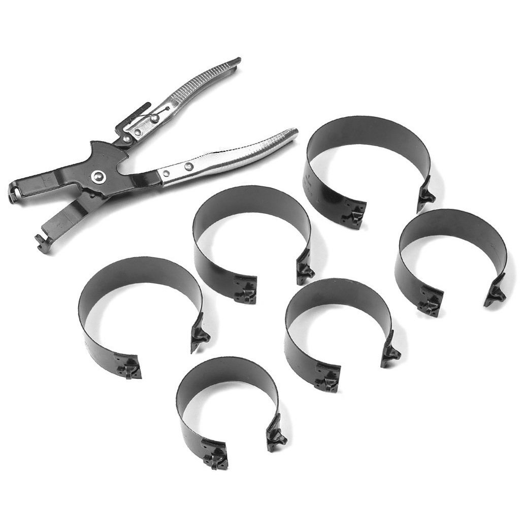
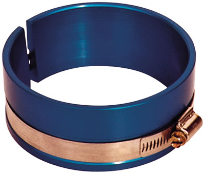
Ive personally found that the piston ring compressors that work best are this type,
this type is far easier to line up to the block surface at a slight angle that allows the rings to partly pop out from under its lower edge just as the rings leave the lower edge of the compressor and enter the cylinders bore, now Im not saying you can,t do it, just that its far easier to do it correctly with this type of ring compressor.IVE dunked my piston/ring assembly's in a can of MARVEL MYSTERY OIL just before installation with a ring compressor and have never seen the slightest indication of problems either on ring sealing getting the rings broken in, or on tearing the engines down later for inspections
http://www.tpub.com/content/constructio ... 24_423.htm
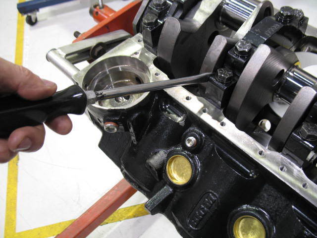
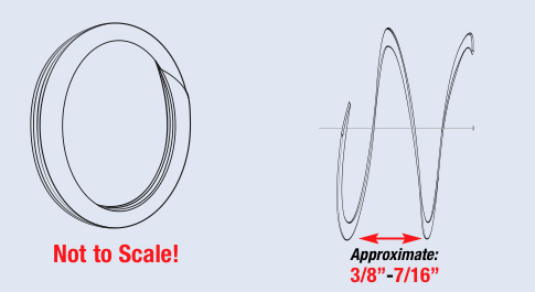
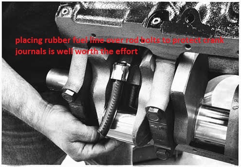
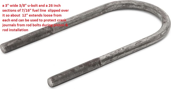
always protect the connecting rod journals from getting scratched during the rod assembly process, a 18" long section of 3/8" or 7/16" inside diam. rubber fuel line can be pushed over rod bolts , after being looped 180 degrees around the rod journal on the crank, if the rod bolts extend down from the rod or a 18" section of 7/16" fuel line with a u shaped section of 5/16" thread rod that's 24" long, bent in the center over a 2.5" section of pipe so the ends remain parallel and even in length can be used as a handy tool so that 3" of the thread rod extends from each end, you then cover all but the last 1" on each end with plastic electrical tape and place the ends thru the rod bolt holes, and thread on a nylon washer and a nut finger tight, can be used as a tool to draw into place a rod on the rod journal if you use cap-screw rod designs
basic rod bearing assembly
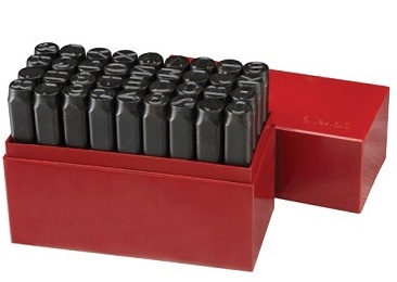
1. Clean the bearing surface of all the connecting rods and connecting rod caps and closely inspect them, in an ideal world they have both the upper and lower should be engraved or stamped so, they can,t get mixed.
2. Clean upper connecting rod bearing and lubricate the bearing face with clean engine oil and moly assembly lube.
3. Clean lower connecting rod bearing and lubricate the bearing face with clean engine oil and moly assembly lube..
NOTE: Align the tabs on the connecting rod bearings with the tab grooves in the connecting rod.
4. Install upper connecting rod bearing in connecting rod, so the bevel on the bearing matches the bevel on the rod and tabs align.
5. Pull the connecting rod and piston assembly into position against the crankshaft. using both a ring compressor, and a rod guide after verifying the ring gap and ring side clearance, ring indexing and the rings are installed with the proper side facing upwards
6. Install lower connecting rod bearing in connecting rod cap.
7. Install bearing cap in position on connecting rod. Ensure that the identification numbers you previously are stamped on the same side, of the rod and rod caps.
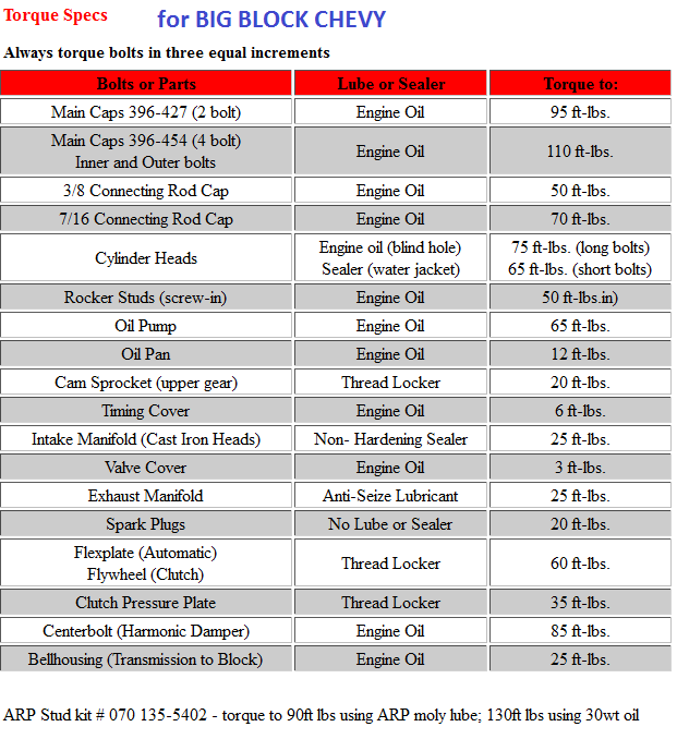
8. If you have Type A connecting rods, install two bolts and two nuts. If you have Type B connecting rods, install two bolts. The torque is very important. verify the correct torque, in this section of the site,and with the connecting rod manufacturer
9. Repeat Steps 1 through 8 for the remaining connecting rod bearings.
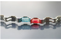
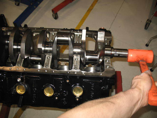
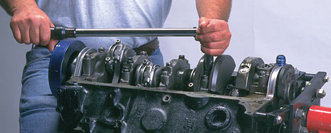
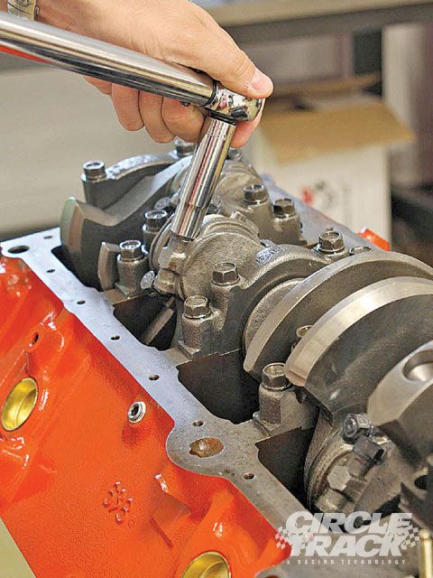
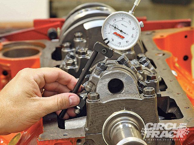
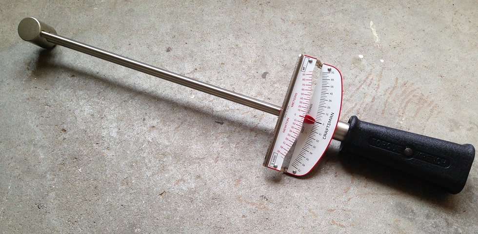
THIS BEAM STYLE TORQUE WRENCH IS THE TYPE TORQUE WRENCH YOU WANT TO CHECK ROTATIONAL RESISTANCE
as to the rotational smoothness, be aware that, all assembly lubes and oil on blocks bore the rings ride over and all bearing surfaces, coated with oil and assembly lube provide a surface shear tension that must be broken before the crank turns,
so its not un-usually for the rotating assembly after the pistons and rings are installed, too require lets say 35 ft lbs to get the assembly too start too spin ,but only 15-26 ft lbs to keep in rotating , (low tension rings provide less drag) you can generally call the piston ring manufacturers and they should know approximately what torque reading on the crank snout,a socket and a torque wrench will require to have the engine assembly rotate with their rings installed.
a crank snout, turning socket,but if that short block assembly,takes over 35-40 lbs to start it rotating once its assembled without cylinder heads attached, you've got serious issues, like cam lobe to connecting roods hitting or a connecting rod facing the wrong way on the crank journal, or the wrong size bearings, or the crank journals not the right size, badly polished or not round
that's why you'll need a torque beam deflection torque wrench to check that
many builder class pistons are designed to go in, in either orientation ,and have both the valve notches and piston pin offset that are identical but most performance pistons have a dot or an F stamped on the crown indicating the side facing the front of the engine, naturally the rod big end bevels face the crank counter weights on each pair and the non-beveled big end faces the matched rod
think carefully about both the initial cost and the structural strength of the engine block you select, the OEM blocks used in production car engines will RARELY accept a .030 plus over bore with out having one or more cylinders having marginally thin bore walls, this results in inadequate bore to ring sealing if its in the wrong area and promotes stress cracks. A .060 over bore in a SBC is rather commonly pushing that bore wall thickness up to or over a reasonable limit so you need to sonic and magnetically check the block for cracks and wall thickness.
you could easily dump $500-$1500 into machine work on a block that won,t last more than a few months under high stress if its not carefully checked PRIOR to the machine work being done.
https://www.amazon.com/dp/B06VXC1FPL/ref=nav_timeline_asin?_encoding=UTF8&psc=1
SBC Piston Ring and Rod Orientation (For the First time Builders)
I was asked a few times after the last video about Piston Ring ring gap orientation aka "Clocking" so here's a video that should help out you first time engi...
www.youtube.com
Jay's Tech Tips #47: Piston Ring Filing - Real Street Performance
Your first time filing piston rings can be tricky until you get the hang of it. Today, Jay walks us through the process of how he files the rings in our race...
www.youtube.com
http://garage.grumpysperformance.com/index.php?threads/engine-balancing.3900/
http://garage.grumpysperformance.com/index.php?threads/block-prep.125/
http://garage.grumpysperformance.co...k-after-a-cam-lobe-rod-or-bearings-fail.2919/
http://garage.grumpysperformance.co...n-wrist-pins-one-really-over-looked-part.978/
http://garage.grumpysperformance.com/index.php?threads/engine-block-cylinder-wall-thickness.976/
http://garage.grumpysperformance.co...tion-of-crank-durring-short-blk-assembly.852/
http://garage.grumpysperformance.com/index.php?threads/why-build-a-383-vs-a-350.715/
http://garage.grumpysperformance.com/index.php?threads/blocks-from-summitt-or-comp-products.10174/
http://garage.grumpysperformance.co...s-why-doesn-t-anyone-ever-ask-or-check.11532/
http://www.bing.com/videos/search?q...&mid=E76F9F78364354FD222DE76F9F78364354FD222D
http://www.hotrod.com/techarticles/hrdp ... ting_rods/
cleaning threads before assembly is always a good idea
check manufactures tech guide info
http://arp-bolts.mobi/p/tech.php?page=3
http://arp-bolts.mobi/p/tech.php?page=2
http://arp-bolts.com/
VERIFYING CLEARANCES GREATLY REDUCES WEAR AND DURABILITY ISSUES
it should be rather obvious that youll need to know the exact distance the piston deck sits at TDC ,above or below the block deck surface and the valve notch recess or pop-up dome volume of the piston to do accurate quench or compression calculations
http://www.harborfreight.com/1-inch-tra ... r-623.html
http://www.summitracing.com/parts/arp-1 ... /overview/ $248
http://www.summitracing.com/parts/arp-1 ... /overview/ $186
yes you can find non-name brand rod bolt stretch gauges from about $50-$80
https://www.enginelabs.com/engine-t...easuring-rod-bolt-stretch-vs-torque-with-arp/
http://www.performanceenginetech.com/connecting-rod-bolts-stretch-vs-torque/
https://www.hotrod.com/articles/using-rod-bolt-stretch-tool/
http://www.superchevy.com/how-to/engines-drivetrain/49258-rod-bolt-torquing-stretch-info/
https://ecatalog.mitutoyo.com/Spindle-Attachment-Tip-C1129.aspx
ARP rod bolts are set up to use a stretch gauge with both ends of the bolt pre-machined for the gauge the bolt packaging from ARP,comes with the correct length the bolts are supposed to reach under the correct pre-load tension, in the instructions OR its available on their web site
most guys are familiar with use of a torque wrench to tighten rod bolts to the correct preload, but while this gets you very close its not as precise as a rod bolt stretch gauge,
having consistent clamp loads are mandatory for proper assembly
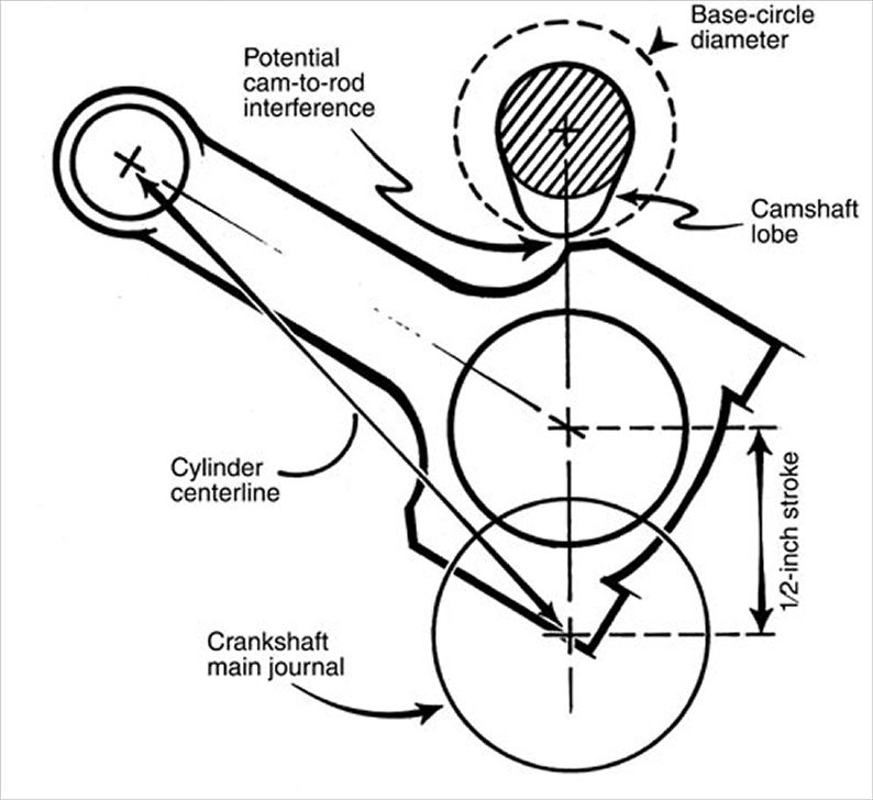
notice how the rod bolts come close to the cam bearings and cam lobes, as the pistons reach top dead canter in the bores, this clearance must be individually checked and should be no less than about .060 (generally you cam use a LARGE plastic tie-wrap
https://www.amazon.com/BuyCableTies...D=41U9CtmwOuL&preST=_SY300_QL70_&dpSrc=detail
placed between the cam lobe and connecting rod bolts or connecting rod shoulder areas to check clearances as the soft tie-wrap will not damage the cam lobe while you verify clearances)you must install the timing set and index the cam correctly to get a valid clearance , as the cam lobes rotate and at some point they can be incorrectly indexed too hit the rods, while they would not if correctly timed.
if you wonder why I suggest using SCAT (H) beam style cap screw connecting rods vs stock or most (I) beam designs this picture should show the increased cam to connecting rod clearance.
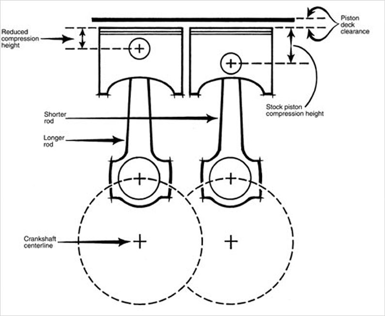
don,t assume anything! when you assemble the connecting rods and pistons there is ALWAYS some minor differences in dimensions,in piston pin height and rod length, VERIFY QUENCH DISTANCE TO THE BLOCK DECK, so youll want too, try to match the slightly shorter rods to the pistons with taller pin locations so the average quench distances is a bit more consistent
one factor to keep in mind is that rods typically have a side that rides against its matched companion and a side thats BEVELED for clearance on the crank journals radias EXAMPLE
notice the top rods non-beveled side that faces the matching rod is up, but on the lower rod the the beveled side that faces the crank counter weight is up on the lower rod
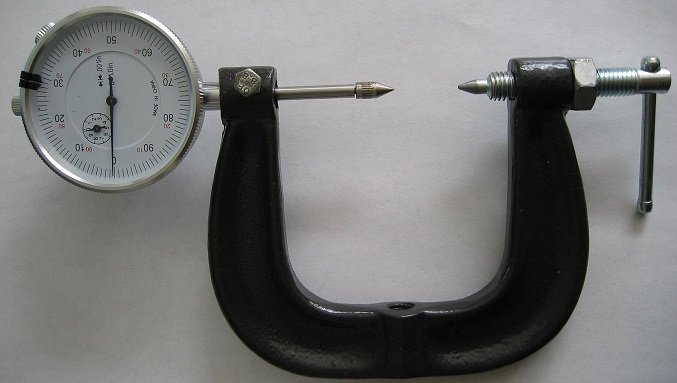
the 80MM-120MM tool fits all chevy V8 engines
BTW I recommend THIS TYPE of piston ring compressor (below)as the type in the video can and occasionally does allow the rings to pop out and jam, or break far more frequently .
the picture lacks detail, but the interior of the compressors tapered, you tighten to a slide fit on the piston diam. and the rings compress fully as they are entering the cylinder entrance and only expand after entering the bore.
BTW when you go to buy a ring compressor....this type works far better than the others
http://store.summitracing.com/partdetail.asp?autofilter=1&part=PRO-66766&N=700+115&autoview=sku
Proform 66766 $31
http://garage.grumpysperformance.co...ng-piston-pin-height-compression-height.5064/
http://garage.grumpysperformance.co...n-wrist-pins-one-really-over-looked-part.978/
if you find the rotating assembly is more difficult to rotate than you expected, you may want to verify some clearance issues that get over looked at times,
theres also some, other potential issues,
theres a slight potential for the piston wrist pins too not rotate effortlessly in the piston pin bores ,
that may add to the difficulty in rotating the assembly in the block.
the piston rings must have vertical and back clearance in the piston ring grooves
Piston Ring Groove Clearance
Pistons are grooved to fit rings that seal the cylinder’s compression and allow for lubrication of the cylinder walls. Piston rings come in a set. There are two compression rings. The top ring is affected by the most cylinder compression pressures. The second compression ring reinforces the top ring. The third ring down is the oil ring. It controls lubrication between the piston and cylinder bore.
Place the new ring into the top piston groove, and then place a feeler gauge into the gap between the new ring and the upper land. Move around the pistons groove and obtain a few measurements. Compare this reading to specifications. If this reading is too much and the gap is too large, the piston must be replaced. The top ring takes the most compression. This causes the ring to slap against and wear the lands in the piston groove.
and of course the pistons must have the correct piston too bore clearance. and connecting rod can only be installed facing one direction
youll be surprised at how much easier they slide into the bore if you BOTH pull/guide and push the pistons into the cylinders rather than just beat them in with a hammer handle, it takes some practice but a few taps to get them moving with a fist, while pulling and guiding the rod into its journal is usually all that necessary with a well oiled piston and that type of ring compressor.
IVE dunked my piston/ring assembly's in a can of MARVEL MYSTERY OIL just before installation with a ring compressor and have never seen the slightest indication of problems either on ring sealing getting the rings broken in, or on tearing the engines down later for inspections
KEEP IN MIND
be sure you, measure EACH bore and EACH piston,
(CORRECTLY with the proper tools in the way the tool and piston manufacturers suggested)
and number them on an engine build sheet indicating the bore and piston diam.
from large to smallest on each and install them on each cylinder to get the most consistent piston to bore clearance's
yes the difference may only be a few ten thousands if the bores are machined correctly, but you'll get the best results , most consistent lubrication, best durability and less heat build up that might result in detonation issues that way. its the little things that add up to making a good durable engine assembly,
BTW check rod orientation, so the beveled sides don't fact the adjacent rods, and check the bearing clearances with plasti guage
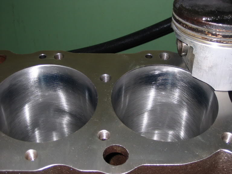
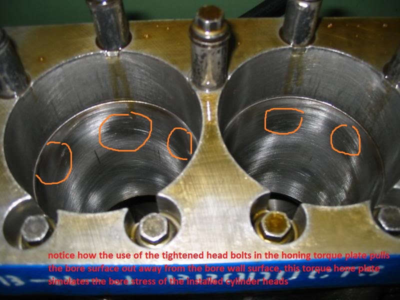
piston to bore clearance
ok first some facts (1)cylinders will not be honed to true round as they will be in use with out the use of a deck plate to simulate and duplicate the bolt clamp stress on the cylinder walls, bores in blocks without a head or deck plate with the bolts or studs torqued to spec are not nearly the...garage.grumpysperformance.com
don,t guess on clearances and journal surface
So I decided to buy a couple of worthless old 283s to learn how to build engines. If I acquire the appropriate skills, I'm going to build a torquey 383 out of the anemic '77 350 in my C30. It tows cars, but it doesn't exactly set the road on fire, if you know what I mean. Anyway, I bought two...garage.grumpysperformance.com
ring gapping and basic piston ring info YOULL NEED
YES YOU NEED TO READ THRU THE LINKS THAT'S WHAT THEY ARE THERE FOR...AND THERE'S A GREAT DEAL OF USEFUL INFO IN THOSE LINKS, don,t get over whelmed, make a list and test adjust correct or replace each problem, and check it off the list then move to the next issue, its a finite list and theres...garage.grumpysperformance.com
assembling and installing connecting rods/pistons
look closely at the connecting rods one edge of the main bearing are is beveled noticeably more than the other that beveled side faces away from the rod its paired with because it matches the slight radiased bevel of the crank journal many builder class pistons are designed to go in, in either...garage.grumpysperformance.com
any ring compressor design you use regardless ,of the design MUST have its lower surface kept firmly in contact with the block surface and parallel to the bore to allow the rings to smoothly transition from the inner surface of the compressor to the blocks bore, and IDEALLY the compressor internal diameter will be marginally smaller in internal diameter that the cylinder bore the pistons sliding into from it!
http://www.engineprofessional.com/TB/EPQ410_10-18.pdf
FOR YOUR OWN GOOD< READ THE SUB LINKED INFO
http://www.kb-silvolite.com/assets/kb_installation.pdf
http://www.connectingrods.net/connectin ... tretch.php
http://www.enginebuildermag.com/Item/38 ... rings.aspx
https://www.uempistons.com/installation ... lation.pdf
when in doubt call the PISTON manufacturer and ASK!
http://www.circletrack.com/enginetech/c ... ce_basics/
http://www.stockcarracing.com/techartic ... index.html
http://www.circletrack.com/howto/1815_c ... to_04.html
http://arrc.epnet.com/autoapp/9102/9102 ... SEMBL1.htm
http://www.corvette-restoration.com/res ... lation.htm
http://www.popularhotrodding.com/engine ... index.html
http://www.pawengineparts.com/shoppingc ... ?catid=206
naturally youll measure the bearing journals
one factor to keep in mind is that rods typically have a side that rides against its matched companion and a side thats BEVELED for clearance on the crank journals radias EXAMPLE
notice the top rods non-beveled side that faces the matching rod is up, but on the lower rod the the beveled side that faces the crank counter weight is up on the lower rod
rod-grinding
on some stroker applications SOME rods need to have the bolts ground for cam lobe clearance
bearings AND connecting rods have an inner facing side and outer side the inner side facing the matching rod has far less edge clearance because they don,t need the radias that is required for the edge of the crank journals
notice the top rods non-beveled side that faces the matching rod is up, but on the lower rod the the beveled side that faces the crank counter weight is up on the lower rod
notice how one side of the bearing holding section has a radias (left)(GOES TOWARD CRANK COUNTER WEIGHT) but the opposite sides flush (right) (FACES MATCHED ROD)
ok lets look at a few things, first , if you look closely at your connecting rods you'll see that one side has considerably more bevel ground on the inner edge of the connecting rod around the bearing than the other side does, to side with that bevel ground on it is to provide clearance for the radius ground onto the crankshaft where the crank throw meets the counterweights like you mentioned, that side of course goes out away from the other rod, to side with far less pronounced bevel is the side where the two connecting rods meet, and ride against each other during normal engine operation normal clearance there is in the area of six to 15 thousands of an inch. When the two connecting rods are correctly torque in place and a feeler gauge is fitted between them to check the maximum clearance.
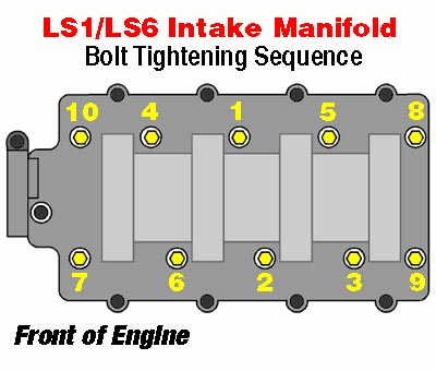
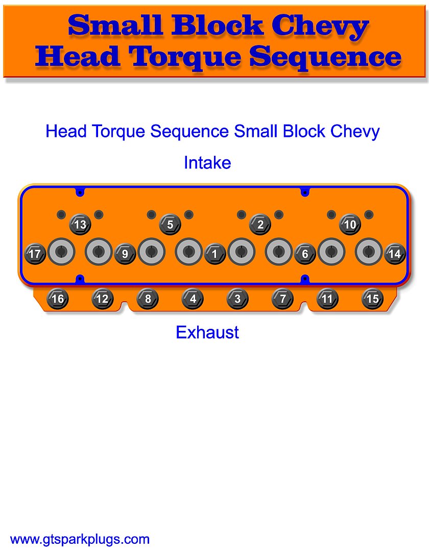
Now a small block Chevrolet the valve placement or valve layout is in this order on a normal head, E I I E E I I E , the letter (E) of course representing exhaust and the letter (I) of course representing intake your Pistons will have to be inserted into the cylinders matching that layout, this will mean there will be two left and two right Pistons on each cylinder bank, if there is a dome on the Pistons it will go towards the outside of the block, when the machine shop installed the Pistons on the connecting rods, they should have been set up with four of the Pistons set up with the exhaust valve notch on the Pistons facing towards the bevel on the connecting rods and four of the Pistons set out live the intake valve side of the Pistons facing that bevel, lets look at the first two cylinders, cylinder number one is the front left forward facing forward look at the diagram per cylinder layout any
on that Piston both the bevel for the Crank Journal that provides bearing clearance and the exhaust valve notch would be towards the front of the engine, but on the next cylinder number two, on the opposite side of the engine. That Piston would have the bevel on the connecting rod facing the rear of the engine, but the exhaust valve notch would be facing the front of the engine, now let's look at cylinders three and four, cylinder number three, would have the bevel on the rod of course facing forward but the exhaust valve notch facing the rear of the engine, on cylinder number four you would have the bevel on the connecting rod facing towards the rear of the engine, and the exhaust valve notch facing towards the rear of the engine, now let's look at cylinders 5 and 6 cylinder number five, bevel forward exhaust forward, cylinder number six exhaust forward but bevel towards the rear for cylinders number 7 & 8 on cylinder number seven, exhaust out notch towards the rear, bearing bevel towards the front of the engine on cylinder number eight bearing bevel towards the rear of the engine and exhaust out towards the rear of the engine
keep in mind that some non- standard head / port layouts can potentially change the piston notch layout
you¢ll also need to make sure youe piston ring end gap is correct, that the piston rings have the correct side facing upwards that the bearings are installed with the correct clearance, and coated with assembly lubricant, that the piston to cylinder block deck clearance is correct ,that your quench distances are correct, and that after you degree in the cam that the piston to valve Clearance is correct. Youll also need to be careful that you don,t hit the connecting rod or rod bolts to the crank journals potentially causing any damage during the installation, and its normal to oil the rings and piston with a lite machine oil during the installation.
Ive personally found that the piston ring compressors that work best are this type,
this type is far easier to line up to the block surface at a slight angle that allows the rings to partly pop out from under its lower edge just as the rings leave the lower edge of the compressor and enter the cylinders bore, now Im not saying you can,t do it, just that its far easier to do it correctly with this type of ring compressor.IVE dunked my piston/ring assembly's in a can of MARVEL MYSTERY OIL just before installation with a ring compressor and have never seen the slightest indication of problems either on ring sealing getting the rings broken in, or on tearing the engines down later for inspections
http://www.tpub.com/content/constructio ... 24_423.htm
always protect the connecting rod journals from getting scratched during the rod assembly process, a 18" long section of 3/8" or 7/16" inside diam. rubber fuel line can be pushed over rod bolts , after being looped 180 degrees around the rod journal on the crank, if the rod bolts extend down from the rod or a 18" section of 7/16" fuel line with a u shaped section of 5/16" thread rod that's 24" long, bent in the center over a 2.5" section of pipe so the ends remain parallel and even in length can be used as a handy tool so that 3" of the thread rod extends from each end, you then cover all but the last 1" on each end with plastic electrical tape and place the ends thru the rod bolt holes, and thread on a nylon washer and a nut finger tight, can be used as a tool to draw into place a rod on the rod journal if you use cap-screw rod designs
basic rod bearing assembly
1. Clean the bearing surface of all the connecting rods and connecting rod caps and closely inspect them, in an ideal world they have both the upper and lower should be engraved or stamped so, they can,t get mixed.
2. Clean upper connecting rod bearing and lubricate the bearing face with clean engine oil and moly assembly lube.
3. Clean lower connecting rod bearing and lubricate the bearing face with clean engine oil and moly assembly lube..
NOTE: Align the tabs on the connecting rod bearings with the tab grooves in the connecting rod.
4. Install upper connecting rod bearing in connecting rod, so the bevel on the bearing matches the bevel on the rod and tabs align.
5. Pull the connecting rod and piston assembly into position against the crankshaft. using both a ring compressor, and a rod guide after verifying the ring gap and ring side clearance, ring indexing and the rings are installed with the proper side facing upwards
6. Install lower connecting rod bearing in connecting rod cap.
7. Install bearing cap in position on connecting rod. Ensure that the identification numbers you previously are stamped on the same side, of the rod and rod caps.
8. If you have Type A connecting rods, install two bolts and two nuts. If you have Type B connecting rods, install two bolts. The torque is very important. verify the correct torque, in this section of the site,and with the connecting rod manufacturer
9. Repeat Steps 1 through 8 for the remaining connecting rod bearings.
THIS BEAM STYLE TORQUE WRENCH IS THE TYPE TORQUE WRENCH YOU WANT TO CHECK ROTATIONAL RESISTANCE
as to the rotational smoothness, be aware that, all assembly lubes and oil on blocks bore the rings ride over and all bearing surfaces, coated with oil and assembly lube provide a surface shear tension that must be broken before the crank turns,
so its not un-usually for the rotating assembly after the pistons and rings are installed, too require lets say 35 ft lbs to get the assembly too start too spin ,but only 15-26 ft lbs to keep in rotating , (low tension rings provide less drag) you can generally call the piston ring manufacturers and they should know approximately what torque reading on the crank snout,a socket and a torque wrench will require to have the engine assembly rotate with their rings installed.
a crank snout, turning socket,but if that short block assembly,takes over 35-40 lbs to start it rotating once its assembled without cylinder heads attached, you've got serious issues, like cam lobe to connecting roods hitting or a connecting rod facing the wrong way on the crank journal, or the wrong size bearings, or the crank journals not the right size, badly polished or not round
that's why you'll need a torque beam deflection torque wrench to check that
Last edited by a moderator: