basic cam install tips, l98, lt1,ls series

grumpyvette

Administrator
Staff member
yes IM only too aware theres a great deal of info to read, but taking your time and doing so will tend to prevent problems later

http://www.hotrod.com/techarticles/engi ... index.html

http://www.hashmarks.com/techtips/hot_cam.htm

viewtopic.php?f=52&t=126&p=1270&hilit=+roller+rockers#p1270

http://shbox.com/1/4th_gen_tech1.html

http://www.jegs.com/InstallationInstruc ... 119661.pdf

http://shbox.com/ci/cam_install.html

http://www.afrashteh.com/guide/install.htm

http://www.chevyhiperformance.com/techa ... index.html

http://www.carcraft.com/howto/ls1_engin ... index.html

http://www.cis.udel.edu/~davis/z28/buildup/cam/

http://www.corvettefever.com/howto/36501/index.html

http://www.corvettefever.com/projectbui ... index.html

http://forums.corvetteforum.com/c4-tech ... r-out.html

http://www.gmhightechperformance.com/te ... index.html

http://www.zmydust.com/headsandcam.html

http://www.bfranker.badz28.com/fbody/guides.htm

http://www.97transam.com/97ta-cam.php

http://www.cis.udel.edu/~davis/z28/buildup/cam/

http://www.corvettefever.com/howto/corp ... index.html

http://www.fierolt1.com/lt1_camdata.htm

http://www.corvettels7.com/halltech_LS900.html

http://www.boxwrench.net/


http://forums.corvetteforum.com/c4-tech ... r-out.html

marks_lined_up.jpg


install it like this, then rotate the engine one time 360 degrees the cam gear will now be at 12 oclock just like the crank gear, then install the distrib pointing at cylinder #1
this may help
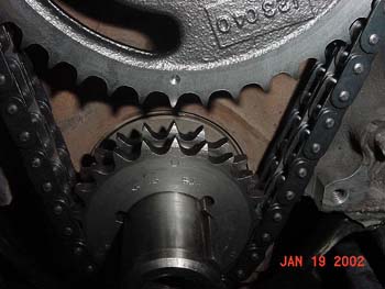
on most aftermarket and on cloyes timing chain sets there are 3 keyways with 3 different marks. There is a:
circle
square
triangle


on the crank gear

0 - Indicates standard cam timing
A - Advances the cam timing 4°
R or a square - Retards the cam timing 4°
how come its 180 degs out of phase? I get this question all the time, well heres something I see lots of guys don,t understand,ONCE YOUVE INSTALLED A CAM WITH THE TIMEING MARKS YOU MUST ROTATE THE CRANK 360 DEGRESS BEFORE DROPPING IN THE DISTRIBUTOR
... while its true that if the
timeing marks are possitioned so the crank is at 12 o,clock and the cam gear
is at 6 o,clock that the cam lobes will be in the possition that fires #6
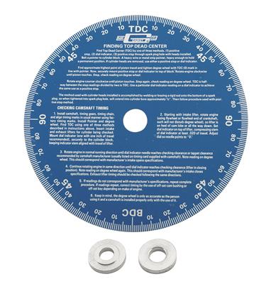
cylinder that HAS NO EFFECT AT ALL (on finding TDC,) for aligning the degree wheel with TDC,or THE timeing tab pointer, for degreeing in the cam, the piston passes thru
TDC TWICE in every fireing cycle once on the fireing/power stroke and once
on the exhaust stroke, the cam rotates at exactly 1/2 the speed of the crank
so to make it easy to line up the marks they install it with the marks at
the closest point 6/12 for easy indexing, rotate the engine 360 degrees to
the #1 TDC power stroke and the crank gear will still be at 12 oclock 12/12
but the cam will be at 12 o,clock also, rotate another 360 degrees and your
back where you started. its simply easier to index the cam at the point
where the index marks align closely. look at how the cam lobes themselfs
open the valves when the cam is just installed the #1 cylinder valves are
slightly open and the #6 are closed
per "Lunati"
""YES YOU ARE RIGHT - WHEN CRANK IS AT TWELVE AND CAM IS AT SIX THEN #6 CYL IS FIRING
AFTER YOU LINE UP YOUR MARKS AND INSTALL GEAR THEN ROTATE YOUR CRANK ONE REVOLUTION AND THEN DROP THE DIST. IN - AT THAT POINT #1 IS FIRING""

use of the dots, as index points will work most of the time in theory, youll be close to correct, if you want things dead on correct you need to take the time to degree it in, the difference can be 5-20hp depending on how lucky you get with tolerances
take the time to read thru the whole thread and sub linked info
its well worth the effort

viewtopic.php?f=52&t=90&p=114#p114

DROPPING THE DISTRIBUTOR BACK IN
viewtopic.php?f=50&t=54


these links may be useful
http://garage.grumpysperformance.com/index.php?threads/adjusting-valves.196/

http://garage.grumpysperformance.co...cally-tracking-down-a-valve-train-noise.6237/

http://garage.grumpysperformance.com/index.php?threads/metal-in-oil.10875/#post-47688

http://garage.grumpysperformance.com/index.php?threads/cam-wear-articles-you-need-to-read.282/

http://garage.grumpysperformance.co...k-after-a-cam-lobe-rod-or-bearings-fail.2919/
 
Last edited by a moderator:
Having installed many dozens of cam installations in cars while the engines were still installed in the car ,ID say the average guy who has some skills and decent hand tools should expect the process to take about two days or most of a weekend,on most cars if hes only done it a few times.
once you've done it a few times on the same car times drop noticeably as experience helps.
two skilled/experienced guys with air tools will drop the time noticeably.
the TPI intake is a P.I.T.A. compared to a carb equipped engine so ID say plan on adding a couple hours for that alone!
plan on starting early on a Saturday and finishing Sunday if your new to the process.

http://forum.grumpysperformance.com/viewtopic.php?f=52&t=90

http://forum.grumpysperformance.com/viewtopic.php?f=32&t=36

http://forum.grumpysperformance.com/viewtopic.php?f=52&t=196

sum-900134_w.jpg

http://store.summitracing.com/partdetai ... toview=sku

pro-66838_w.jpg

http://store.summitracing.com/partdetai ... toview=sku

cca-4914_w.jpg

http://store.summitracing.com/partdetai ... toview=sku

mrg-1570.jpg

http://store.summitracing.com/partdetai ... toview=sku

sum-900189_w.jpg

http://store.summitracing.com/partdetai ... toview=sku


Fuel Injection Engine Camshafts: BY ERSON CAMS

For a camshaft to work in a fuel injected application, it needs to make a good vacuum signal.
To create a vacuum signal, that stands a reasonable chance at working in an application without having to re-flash the ECM computer, a camshaft needs to be:

a) Short Duration : 220-222 Degrees @ .050” Maximum

b) Wide Lobe Separation/Centers: 112 to 114 degrees Minimum
Do not attempt to install a camshaft with a 108 lobe separation in a fuel injected engine, unless you are planning to re-program the ECM computer.

There are camshafts that are ground to work within the stock ECM computer parameters. Usually these camshafts have 208/208 degrees duration @.050” (intake/exhaust) and 112 degrees of lobe separation, or 208/214 duration with a 114 L/C

Both of these camshafts would be designed to function in stock CID engines/stock compression and stock computer programming.

However, if the cubic inches of the engine or compression ratio is larger than stock, the camshaft grind needs to grow accordingly and a custom camshaft would be in order.
Also, having the computer re-programmed/re-flashed is recommended with any camshaft change, even the “no hassle/safe” type grinds.

While the camshaft may work with the stock fuel/timing curve programmed into the ECM unit, it will not be working at its optimum level…..Think of it along the lines of taking a performance carburetor out of the box, bolting it onto the engine, hooking up the fuel lines and running it. It may run but without tuning/jetting the carburetor to the engine, it will not work to its full potential.

While we are on this subject, there are some engines that you need to be wary of:

* Late 80’s-Early 90’s 350 Chevrolets with a K engine code and an idle speed of 500 R.P.M. (TBI)
* Early Ford V-8’s with the Speed Density fuel injection.
* Dodge Magnum V-8’s
* Any Fuel Injected application where the customer wants a loud/radical idle.
the LASH/PRELOAD on a lifter determines several things and one of those is the voluum of oil forced up the pushrod and the valves abilty to bleed off heat to the heads thru the seat contact.
minimizing the preload allows slightly longer seat contact and greater oil flow to the valve train and less likely hood of burnt valves.
the oil trapped under the pushrod seat in the lifter supports the pushrod and can,t be compressed easily , the total distance for preload adjustment most lifter seats have available is in the .060 range, if you minimize the preload the oil reaching the valve train as the seat collapses and forces it up the pushrods increased, as the lobe spins under the lifter, total valve lift may be very slightly effected , but Ive always prefered durrability over trying for the last possiable bit of peak power.
keep in mind , that clearance is set on a relatively cool engine, once you start running it hard the temp. increases rapidly and that lifter and valve train expand due to heat, minimal valve train clearances, and limited oil flow to cool the springs might become a problem, especially when you realise that about 40% of the engine heat comes not from combustion but from the valve train and springs, and friction, valve springs glow red hot and fail in under 5 minutes at 6000rpm with no oil flow to cool them according to SMOKEY YUNICKS TESTING.
you also must keep in mind that as the rpms increase the TIME available for the lifter to bleed off oil under the lifter seat decreases rapidly, resulting in slightly higher effective lift at the valve.
you might want to keep in mind valve preloads usually set while the engines not nearly as hot and the expansion, of the components due too heat is minimal compared to the conditions durring a race, where extra clearances may be necessary in the valve train once everything reaches true opperational heat levels.

http://www.type2.com/library/engineg/hydral2.htm

http://www.ratwell.com/technical/HydraulicLifters.html
15-Exploded.jpg


hydr1.png

hydr2.png

watch this video, it depicts the lifters movement as the cam lobe rotates under its base forcing it up as the lobes ramp, rotates under the lifter base,removing the clearance slack,
as it compresses the valve spring and forces the trapped oil, up the push rod and lifts the valve

If you are concerned with measuring the clearance in the hydraulic lifter seat when selecting and measuring the correct valve train geometry,
so you can order the correct length push rods...
I don,t think you have the correct idea as to how hydraulic lifters work,
yes it is possible for an engine with hydraulic lifters to be pushed too operate at a high enough rpm that the time required for the lifter seat to fully depress and all the oil too be forced up to the push rod/rockers , to be so short that the lifter pumps up and the valves will have less seat time, ( sometimes one of several factors, like the lifter leaving the cam lobes surface as the inertial loads exceed the valve springs ability to maintain lifter too lobe contact, referred too or contributing to what is commonly referred too as valve float) but that has ZERO to do with selecting push rod length or proper valve train geometry, (remember at 6000 rpm the valve is lifted off its seat 50 times PER SECOND)
hydrlifth.jpg


12cal.jpg

prctool.png

http://www.summitracing.com/search/...d-length-checkers?autoview=SKU&ibanner=SREPD5
Proform Pushrod Length Checkers 66789 SBC 3/8" rocker studs

Proform Pushrod Length Checkers 66790 SBC 7/16" rocker studs

Proform Pushrod Length Checkers 66806 BBC 7/16" rocker studs
http://garage.grumpysperformance.com/index.php?threads/valve-train-clearances-and-problems.528/

http://garage.grumpysperformance.co...e-springs-and-setting-up-the-valve-train.181/

http://garage.grumpysperformance.com/index.php?threads/stock-gm-push-rod-length.3844/

http://garage.grumpysperformance.com/index.php?threads/rocker-push-rod-wear-issues.9815/

http://garage.grumpysperformance.co...1-6-1-ratio-rockers-and-the-pushrods-rub.198/

http://garage.grumpysperformance.co...mall-block-chevy-guide-plates.2839/#post-7344


http://garage.grumpysperformance.com/index.php?threads/decent-deal-on-these-push-rod-length-checker-tools.13735/#post-70650

http://garage.grumpysperformance.co...rockers-which-is-best-steel-or-aluminum.3124/

http://garage.grumpysperformance.com/index.php?threads/valve-springs.9613/

http://garage.grumpysperformance.co...lve-springs-loads-and-installed-height.10709/

http://garage.grumpysperformance.com/index.php?threads/press-in-vs-threaded-rocker-studs.2746/

http://garage.grumpysperformance.co...s-changing-rocker-ratios-and-the-effects.126/
http://garage.grumpysperformance.com/index.php?threads/understanding-valve-spring-bind-height-060-safety-margin.4957/

ALWAYS READ LINKED INFO IN THESE THREADS ON THIS WEB-SITE
have you used one of the push-rod length checker tools?
prctool.png

they might be a good cross check, before you order the push-rods.
it would take a bit more time but it would be cheaper in the long term.
to be sure you got it right than it would be to try to return push-rods
remember the tool works when the lifters on the cams base circle
(yes as simple as they are (PICTURE ABOVE) too use they tend to be rather accurate)
yes I use BOTH the push rod checker tools to get the quick check on length, and the adjustable length push-rods and a marker too method verify the correct length with a cross check by looking at the wear/sweep and location, on the valve tip
valvetip.jpg

http://garage.grumpysperformance.co...sh-rod-length-checker-tools.13735/#post-70650

http://garage.grumpysperformance.co...rdering-correct-custom-length-pushrods.14241/

http://www.summitracing.com/search/...d-length-checkers?autoview=SKU&ibanner=SREPD5
Proform Pushrod Length Checkers 66789 SBC 3/8" rocker studs


Proform Pushrod Length Checkers 66790 SBC 7/16" rocker studs


heres a bit of useful related push rod length info (POSTED HERE) youll want to select the correct set or SETS for your shop

Big Block Chevy, Standard Length Big Block Intake 3/8" / .080" 8.275"
295-7941-8 Big Block Chevy, Standard Length Big Block Exhaust 3/8" / .080" 9.250"
295-7969-8 Big Block Chevy, Standard Big Block +.100" Long Intake 3/8" / .080" 8.375"
295-7979-8 Big Block Chevy, Standard Big Block +.100" Long Exhaust 3/8" / .080" 9.350"
295-7951-8 Big Block Chevy, Standard Length Big Block Tall Deck Intake 3/8" / .080" 8.675"
295-7961-8 Big Block Chevy, Standard Length Big Block Tall Deck Exhaust 3/8" / .080" 9.650"
295-7800 V8 396-454 Retro Fit Pushrod Set, Intake & Exhaust, 1965-Present
3/8" / .080"
3/8" / .080" 7.725 Int.
8.675 Exh

295-7913-16 Small Block Chevy, Standard Length Small Block Chevy 3/8" / .080" 7.800"
295-7984-16 Small Block Chevy, +.100" Long 3/8" / .080" 7.900"
295-7934-16 Big Block Ford, Standard Length Ford `72-'78 429-460 3/8" / .080" 8.550"
295-7951-16 Big Block Ford, Standard Length Ford `69-'71 429-460 3/8" / .080" 8.675"
295-7582-16 Oldsmobile, Std Length 455 5/16" 9.550"


These engines/computer combinations have very special camshaft grind requirements, so should you run into one of these combinations, it would be best to call the Erson Tech Line (775/246-4062) for a recommendation.
 
Last edited by a moderator:
I know some of you gentlemen would rather dig your own eyes out of your face with a rusty fork than read links, sub-links and posted info, but amazingly there useful info , in them, like tools that let you detect cam wear early, when to swap filters
what lubes to use,how to adjust and clearance valve trains, use of magnets to trap metallic crud and limit damage, which filters to use, etc.

the total amount of assembly lube you put on the cam and rotating assembly rarely can exceed 4 OZ and that EASILY fits into an oil filter, so if your getting more crud than the first oil filter traps in the first 30 minutes during the engine brake-in process, logic says its COMING from someplace and a quick look at the filter internals with the tool linked above and the magnets you should have installed should give you a good idea as to the source:thumbsup:

http://store.summitracing.com/partdetail.asp?autofilter=1&part=SUM-900510&N=700+115&autoview=sku
sum-900510.jpg


http://forum.grumpysperformance.com/viewtopic.php?f=44&t=799&p=1161#p1161

http://forum.grumpysperformance.com/viewtopic.php?f=32&t=939&p=1582&hilit=+filter+tool#p1582

http://forum.grumpysperformance.com/viewtopic.php?f=52&t=282
 
hey grumpyvette?
,VETTEOZ has offered to sell me his trick flo 195cc heads off his car and has a selection of cams he can offer me to suit my set up on my car.


these are the cams

CRANE #119661
PowerMax Hydraulic Roller Tappet Retrofit Camshaft
Lift: .539''/.558''
Duration: 292°/300°
RPM Range: 3000-6500
http://www.cranecams.com/index.php?show=browseParts&action=partSpec&partNumber=119661&lvl=2&prt=5
this is the cam I run in my 383, it requires a 3.73 rear gear and a manual trans or 3000 rpm stall converter , and about 10.5:1 cpr and its really not a very good street cam, but with a 150hp shot of nitrous it produces exceptional hp

LINGENFELTER#219
Lingenfelter 74219 Camshaft L98, LT1, LT4 1987 - 1996 TPI - Hydraulic Roller 219/219 .560/.560 HR112
Part Number: L210035087
a really nice design,for street/strip use, but verify clearances carefully


COMP CAMS#306
Chevy 350ci LT1 & LT4 1993-96

For use with LT1 modified computer, intake plenum, runners and 2500 stall converter.

Operating Range: 1800-5800 RPM
Duration Advertised: 290° Intake / 307° Exhaust
Duration @ .050'' Lift: 230° Intake / 244° Exhaust
Valve Lift w/1.5 Rockers: .510'' Intake / .540'' Exhaust
Lobe Separation Angle: 112°

this will make your car idle sound mean like a dragster but cost you performance ,that some of the others provide, this ID avoid it like the BLACK PLAGUE victim with AIDS


TPIS#zz409
ZZ-409 Hyd Roller:
This is the next step up great cam for a stick car
Advertised Duration 287/287
Duration @.050 226/226
Gross Lift .520/.520
Lobe Seperation 112
this is probably one of the best street/strip cams listed here, I liked it, and its low valve train stress, it will most likely give you the best compromise and Id think hard about this one, if the cars used for transportation rather than a weekend toy


what do you reckon ??????[/QUOTE]


does that help,
every choice is a compromise and slapping a new cam and heads on your engine won,t provide its full potential without the low restriction 3" exhaust, tuned headers, and 3.54-3.73 rear gears that match, the new cams rpm band and an intake that flows at least as much as the heads do,
Ive tried all of those cams listed at one time or another in my car or friends cars, all but the comp design, and personally I won,t even think of running one of those POSSER THUMPER CAMs
OBVIOUSLY youll need to verify clearances and ID strongly suggest NEW hydraulic roller lifters, and roller rockers be used
 
Back
Top