now think it thru,
HERES SOME USEFUL INFO, that might help in this thread and the sub links
http://garage.grumpysperformance.com/index.php?threads/crank-case-blow-bye-and-related-info.16790/
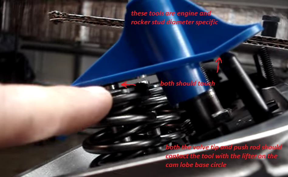
the first thing Id be doing here, if your not getting a strong oil flow at each rocker while your turn the engine manually and use the oil priming tool, is carefully visual checking of BOTH the valve train rocker geometry and that the push rods are completely hollow and free of debris, by cleaning each with solvent and high pressure air, then mocking the drive train up and verifying that BOTH the rocker and push rod oil feed holes line up at some point in the 720 degrees of rotation, and that the bottom end of the push rods stay aligned with the center of the lifters, seat, this might sound like its a assumed fact, but its easily possible for the push rods to bind on the push rod guide plates or guide slots in the cylinder heads, this potential BINDING will move the push rod , out of its seat on the lifter or rocker preventing proper oil feed out of the lifter or rockers proper alignment, if the oil feed holes are not properly lined up oil won't flow freely.
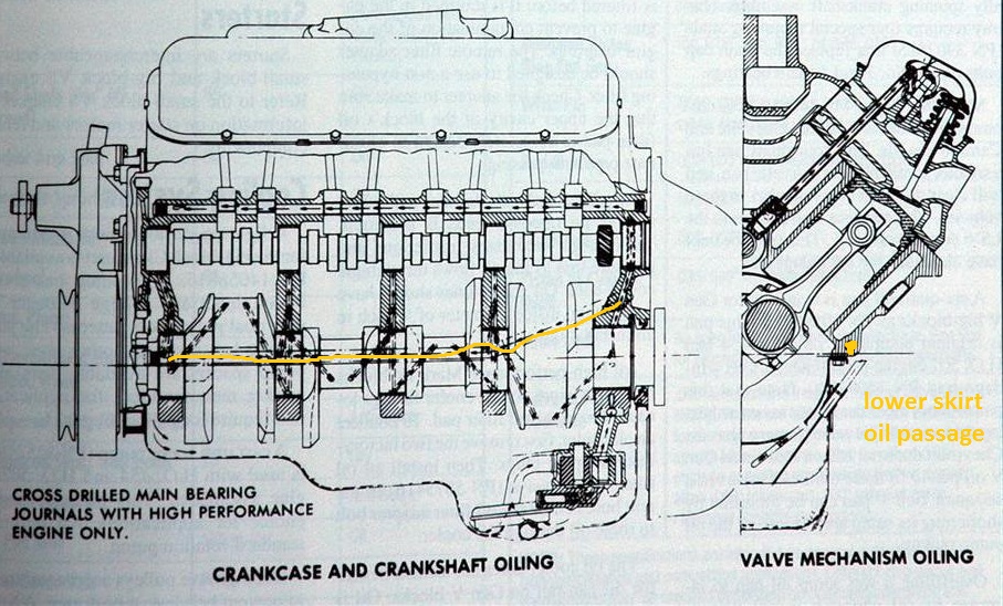
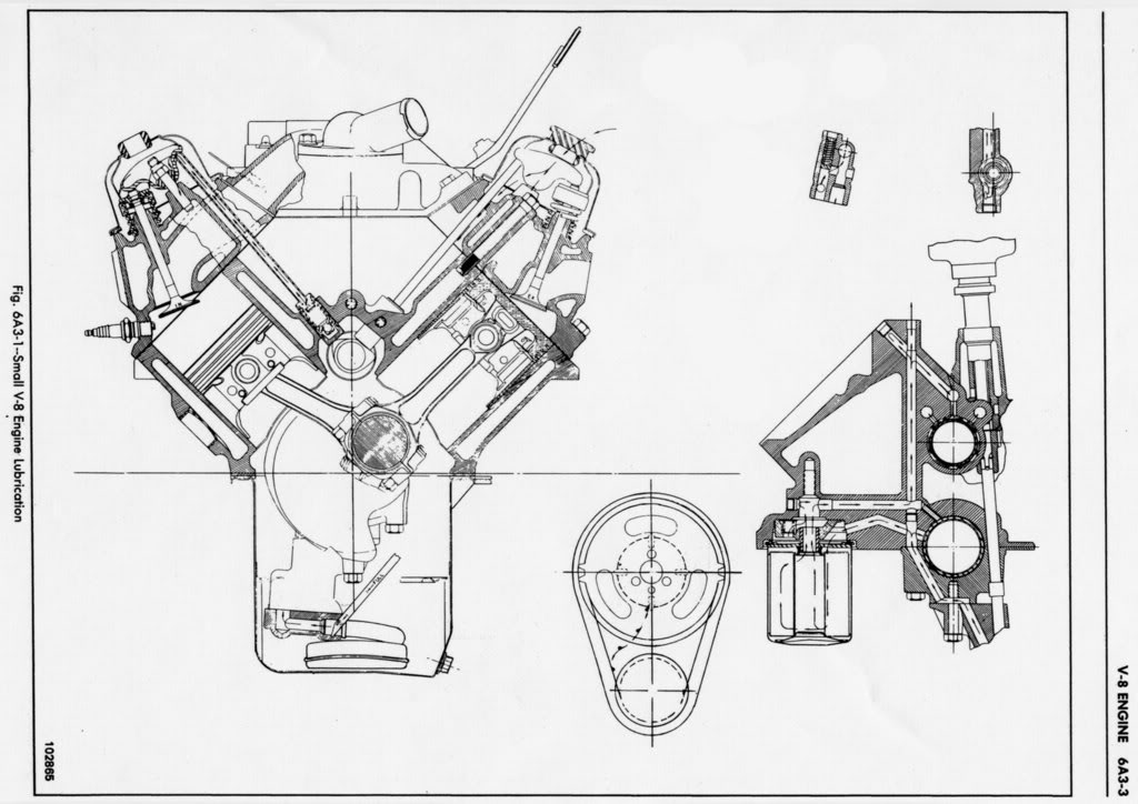
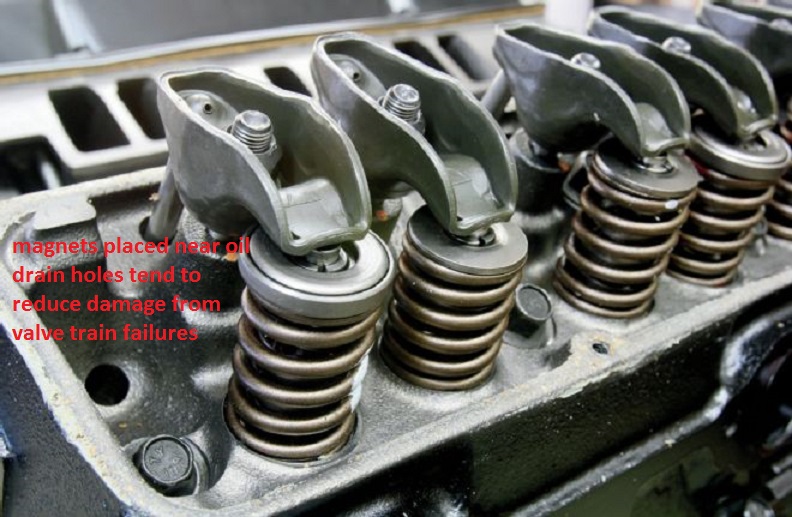
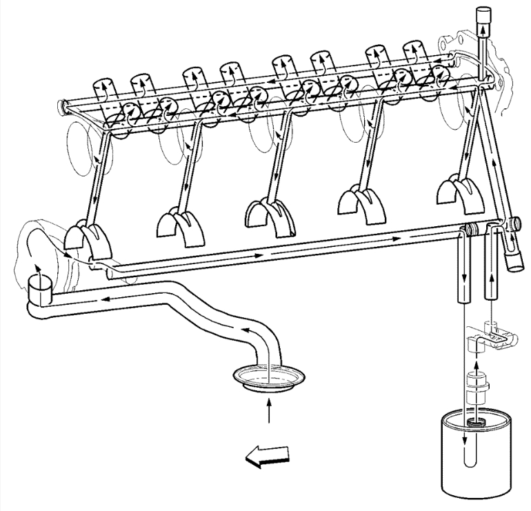
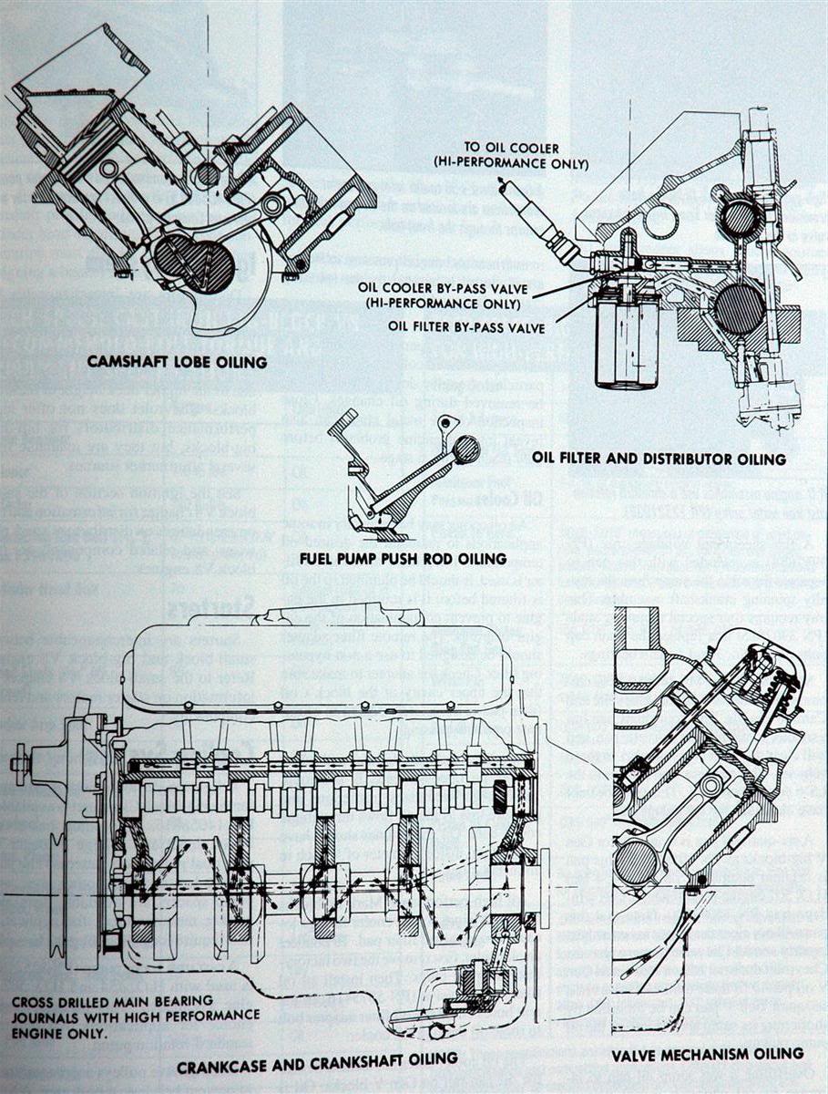
the oil mist bath, being constantly thrown from the rotating crank assembly unto the lower bore walls,and rockers over the valve train,valve springs, rockers,rods and underside of the pistons does A GREAT DEAL of the initial heat absorption and heat transfer,
and prevents the pistons and rings from being damaged,
only as the hot oil falls, and drains back into the lower sump is much of the heat transferred to the coolant in the block.
oil flow and coolant flow are both required to absorb and remove heat build-up from the engine,especially from the rotating assembly , bearings,and valve train components
http://www.chevyhiperformance.com/techa ... index.html
http://www.melling.com/Aftermarket/Tech-Tip-Videos
http://www.mellingengine.com/TechnicalS ... etins.aspx
viewtopic.php?f=54&t=3536
Chevrolet Performance 14091563
Left (Driver Side) Dipstick Plug
Chevrolet Performance 9421743
Right (Passenger Side) Dipstick Plug
On oil pans I prefer studs, and an oil pan back plate
you might want to Use with P/N 12553058 RH and P/N 12553059 LH oil pan reinforcement plates to distribute the bolt stress on the oil pan rail for 1985 and earlier oil pans P/N 14088501 (LH) and P/N 14088502 (RH).1986 and newer
thats a very common question but the answers no!
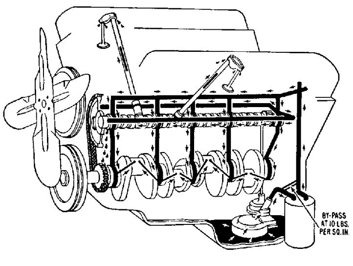

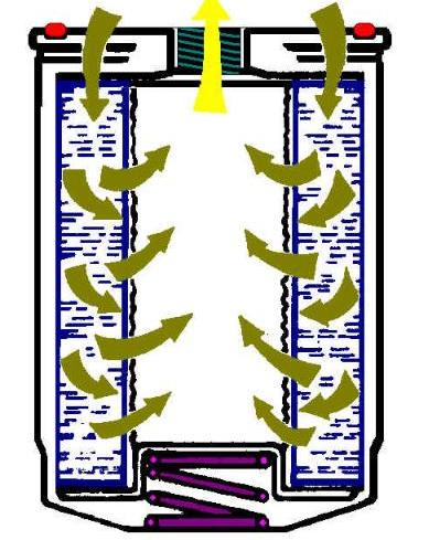
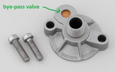
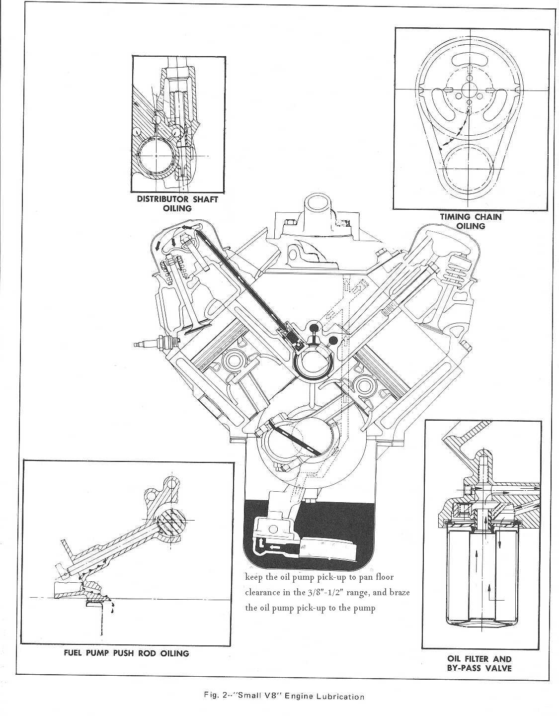
ALL THAT OIL FILTER BYE-PASS VALVE DOES IS ROUTE OIL FLOW PAST THE OIL FILTER
IF IT BECOMES SO CLOGGED WITH TRASH THAT THERES
A 10 PSI DIFFERENCE IN THE RESISTANCE TO OIL FLOW THROUGH THE FILTER
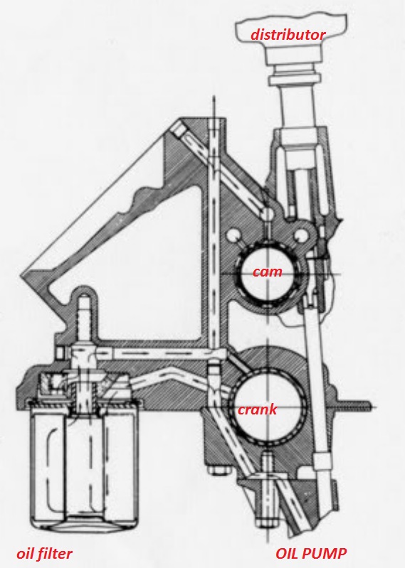
VS AROUND IT INTO THE BLOCKS OIL PASSAGES, oil enters the area over the oil filter in the block and is forced into the outer holes in the oil filter perimeter down through the case and filter element and up through the central hollow screw retention stud into the blocks oil passages, if the resistance too flow is too great the oil filter bye-pass valve routes oil around the filter directly from oil pump to the blocks oil passages.

MORE USEFUL INFO
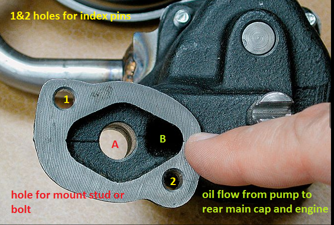
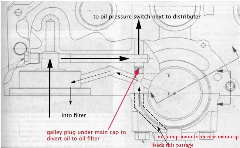
yes the oil flows around the mounting stud,from oil pump to main cap to reach the engine oil passages, thru the oil filter
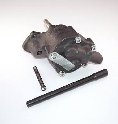
failure to use the correct oil pump,mounting stud, bolt or nut or carefully check clearances when mounting an oil pump can cause problems
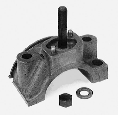
ONE RATHER COMMON MISTAKE IS USING THE WRONG OIL PUMP STUD OR BOLT TO MOUNT THE OIL PUMP AS IF EITHER EXTENDS THRU THE REAR MAIN CAP IT CAN AND WILL BIND ON THE BEARING AND LOCK OR RESTRICT, SMOOTH ROTATION
http://garage.grumpysperformance.co...-friction-and-pumping-losses.8966/#post-31978
viewtopic.php?f=54&t=4537
http://www.improvedracing.com/tech/LS-o ... nsions.php
http://www.stevesnovasite.com/forums/sh ... p?t=208618
http://www.enginebuildermag.com/2018/06/performance-oiling-systems-2/
http://ls1tech.com/forums/conversions-h ... -pans.html
viewtopic.php?f=52&t=788
http://www.nonlintec.com/sprite/oil_myths.pdf


pressure is a measure of RESISTANCE to oil flow, if the pumps providing flow and yes that needs to be verified,
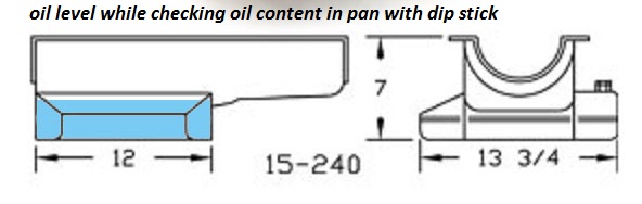
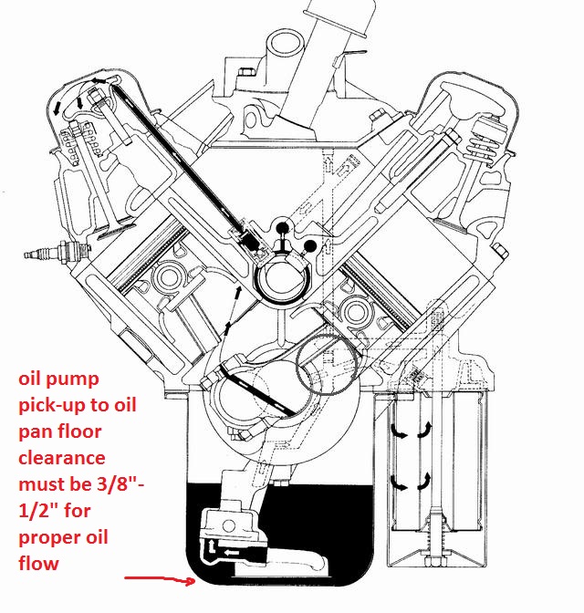
( because if the oil pump pick-up is less than a 1/4" off the oil pan floor flow is potentially restricted)
if your getting oil flow from the oil pump and no back pressure Id suggest checking the flow control valves, bearing clearances and oil passage plugs at the ends of the lifter gallery passages, any major open to flow oil passage results in very low oil pressure readings
http://garage.grumpysperformance.co...ark-v-bbc-engine-oil-system-differences.4576/
https://www.chevydiy.com/oil-lubrication-systems-guide-big-block-chevy-engines/
https://paceperformance.com/i-51345...ich-adapter-for-external-oil-cooler-only.html
http://garage.grumpysperformance.com/index.php?threads/basic-info-on-your-v8-lube-system.52/

https://www.chevydiy.com/oil-lubrication-systems-guide-big-block-chevy-engines/
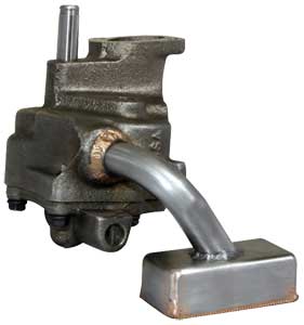
use this oil pump(link below) in most stock SBC builds, as it produces a 10% increase in oil volume and standard pressure which is just fine , but obviously check your bearing clearances and oil pump to oil pan floor clearances and braze the CORRECT MATCHING pick-up to the pump, and I,d also suggest if you have the room, for clearance that you look into one of the less expensive 7 quart baffled oil pans as they provide a good deal more potential protection and durability to your bearings longevity. be very sure you verify the oil pump pick-up to oil pan floor clearance, and braze the pick-up to the pump body.
yes theres less expensive oil pumps that will work, but thats a good value, in a well made pump.
first choice
http://www.summitracing.com/parts/mel-10552/overview/ SBC
or
http://www.jegs.com/i/Melling/689/10778C/10002/-1 BBC
second choice
http://www.summitracing.com/parts/mil-18750/overview/ SBC
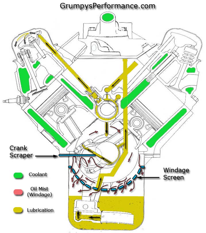
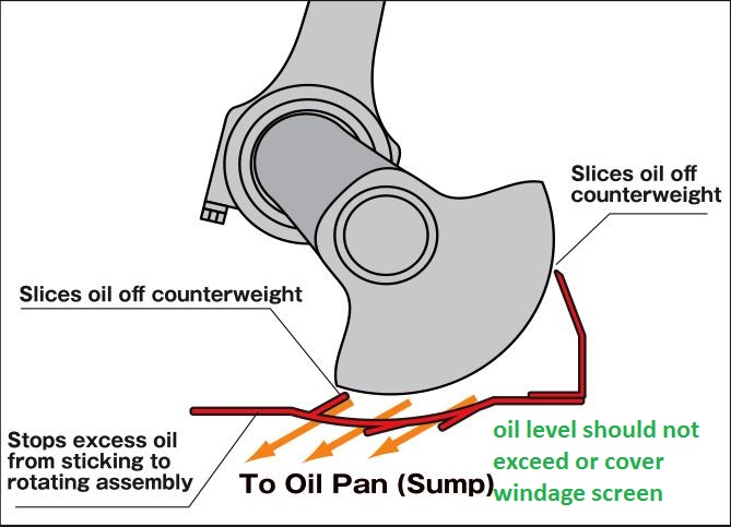
ADDING A WELL DESIGNED WINDAGE SCREEN SPEEDS OIL RETURN SPEEDS . AND EFFICIENCY TO THE ENGINE SUMP
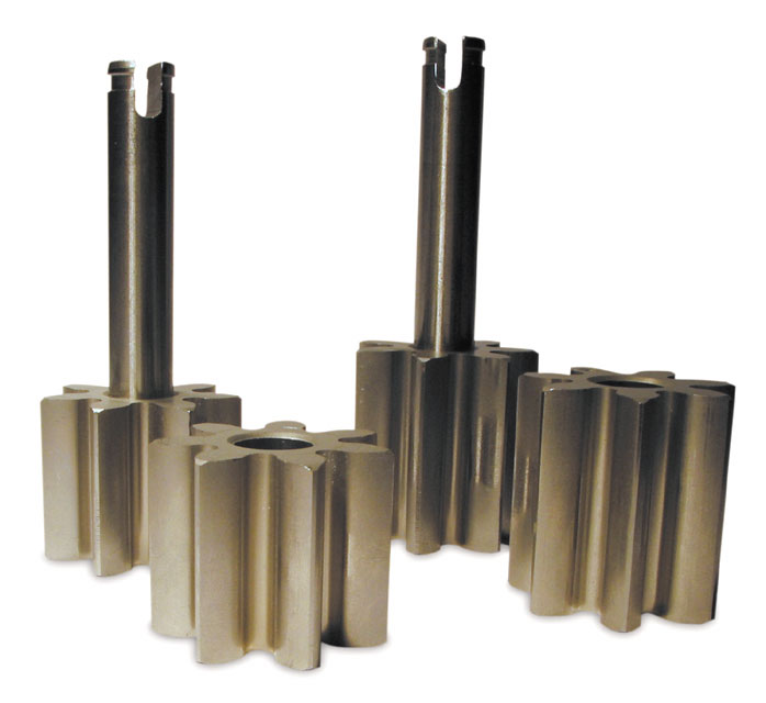
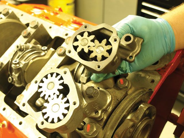
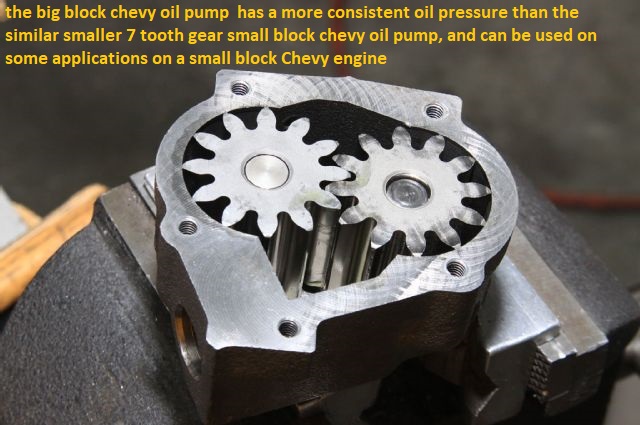
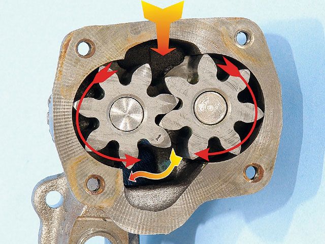
keep in mind the sbc oil pump has 7 tooth gears and the big block pumps have 12 teeth making the oil flow smoother and less pulsed, plus having larger gears they tend to supply more oil at lower rpms
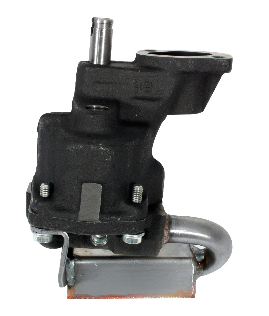
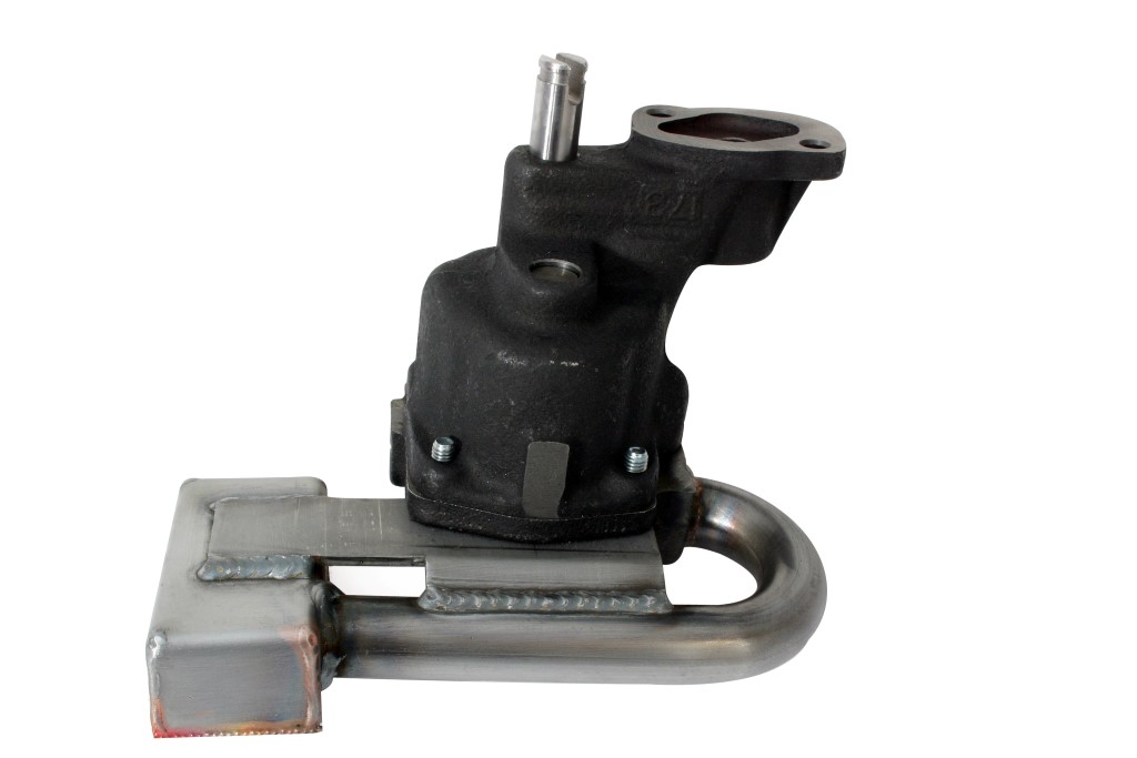
look closely and youll see the big block oil pump has a 5 bolt lower cover and the oil pump pick-up with its 3/4" feed seats into the main pump casting while the small block oil pump has a 4 bolt cover and the sbc oil pump pick-up with its 5/8" feed seats into the pumps cover plate
Id also point out that its virtually impossible , in a well designed engine to run the engine "long enough to pump all the oil upstairs."[/img]
as with a properly designed baffled oil pan, with a carefully fitted and clearanced windage screen and crank scraper, the oil pump simply reaches a flow rate pumping oil out of about 100 or so potential lubricant flow leakage points
OIL PRESSURE read on the oil pressure gauge is a MEASURE of RESISTANCE to oil flow, you can REDUCE the pressure the gauge reads by either increasing the engine clearances or REDUCING the oil viscosity (thickness) so it flows thru the clearances faster with less resistance.(OR INSTALLING A SLIGHTLY WEAKER OIL PUMP BYE_PASS SPRING,that limits the pump pressure before it allows some oil to re-circulate back through the bye-pass valve ,from the high pressure back to the low pressure side of the pump impellers, but only the max pressure you reach is limited by the bye-pass spring,in your oil pressure bye pass circuit and its that spring resistance determines the point where the bye-pass circuit, opens and limits max oil pressure, but the bye-pass circuit has zero to do with anything else, if its functioning correctly,
there are many oil leakage points(100) in a standard Chevy engine.
16 lifter to push rod points
16 push rod to rocker arm points
32 lifter bores 16 x 2 ends
10 main bearing edges
9 cam bearing edges
16 rod bearing edges
2 distributor shaft leaks
1 distributor shaft to shim above the cam gear(some engines that have an oil pressure feed distributor shaft bearing.)
once oil exits the bearings or valve train it flows mostly by gravity back to the oil pan sump, but a properly designed windage screen and crank scraper correctly clearanced allows the spinning crank/rotating assembly to act like a directional pump that drags the vast majority of the oil flow back to the sump, by design.
your 55 psi at idle serves no purpose as 15psi-25psi is all thats expected in a new engine with tight clearances using a good 10W30 oil, if your using a higher viscosity than 10w30 its reducing oil flow rates and reducing heat transfer rates, Id suggest using a good 10W30 oil. and use of a 7-8 quart, baffled oil pan and windage tray
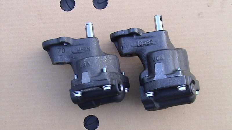
(NOTICE ITS A 4 BOLT small BLOCK HIGH VOLUME OIL PUMP WITH A 5/8" pickup}
10553
10553High pressure performance upgrade for M-55 & M-55A.
Standard volume oil pump.
The 10553 housing and cover are CNC machined and phosphate coated.
Manufactured with pink spring installed for higher pressure (M-55A).
To change pump to lower pressure (M-55) install the supplied yellow spring.
Includes intermediate shaft with steel guide.
The 10553 uses a 5/8” press in screen.
10552
High volume performance oil pump.
10% increase in volume over stock oil pump.
The 10552 is manufactured with the drive and idler shafts extended to allow for additional support in the cover eliminating dynamic shaft deflection at increased RPM levels.
The cover is doweled to the pump housing to assure alignment of the shaft bores.
Screw in plug retains relief valve spring instead of pin.
Relief hole in cover uses screw in plug instead of pressed cup plug.
All bolts are self locking socket heads, with the wrench supplied.
The housing and cover are CNC machined and phosphate coated.
Includes intermediate shaft with steel guide. Uses both 3/4” bolt on or press in screen.
The lower pressure spring is included to reduce pressure if desired.
Patent No. 5,810,571.
10778C (Anti-Cavitation)
(NOTICE ITS A 5 BOLT BIG BLOCK HIGH VOLUME OIL PUMP WITH A 3/4" pickup}
http://www.summitracing.com/parts/mel-10778
High volume performance upgrade for the 10770.
Increase in volume of 25% over stock oil pump.
The same as the 10778 except with the addition of grooves machined in the housing and cover. The grooves reduce cavitation effects in high RPM applications.
Using this oil pump will reduce pressure at idle.
Includes intermediate shaft with steel guide.
Uses 3/4” press in screen.
Racing applications only.
Patent No. 5,810,571
from chevy high performance mag


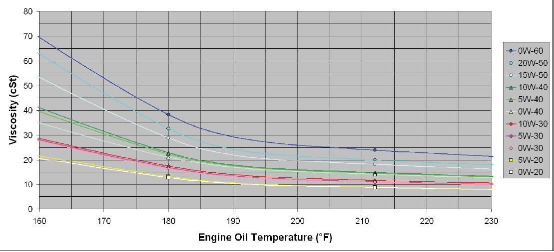
keep in mind that as oil temps increase the oil viscosity tends to decrease, thus cold oil, at lets say 70F might cause the oil pressure gauge to read 50 psi at idle but the pressure reading slowly goes down to 25 psi once the oils reached lets say 210F, this is normal and expected
you might want to read thru these links and sub links,
as theres a great deal of related useful info contained
viewtopic.php?f=54&t=3536
viewtopic.php?f=54&t=2187
viewtopic.php?f=54&t=2102
viewtopic.php?f=54&t=64
viewtopic.php?f=54&t=1334
(1)pressure is the measure of resistance to oil flow
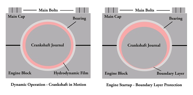
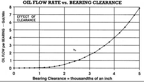
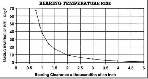
If you decrease the viscosity to a lighter oil, you tend to increase flow at a loss of pressure. High flow helps to carry away more bearing heat at a faster rate, but it must be balanced with the pressure levels, High pressure helps to keep metal parts like the crank and rod bearings out of direct contact with each other as they are separated by a film of supporting oil (scuffing).â€
(2) the high volume pump can push about 25% more oil , high flow rates result in more heat transferred from bearings, and rockers and valves ETC. to the oil flowing thru the clearances
(3) the oil pump bye-pass circuit limits the max pressure in either size pump to about 65lbs-75 lbs MAXIMUM before it BYE-PASSES enough additional oil volume to limit the pressure
(4) the engine can accept and use only the max flow volume that the engine passages, and clearances can flow at the max pressure the pump provides , at any point less than max pressure the passages can flow only what the pressure and volume provided by the pump supplies
(5)if the bearing clearances can flow more than the pump provides in volume and pressure at any rpm level the film of cooling oil that provides a cushion between the bearing surfaces are at risk of not being supported and separated by that cushion of flowing oil
(6) now since the sweep volume is greater with the high volume pump it will reach that bye-pass circuits max pressure at about 25% lower rpms and supply a POTENTIALLY higher volume of oil to the supply passages/bearings
(7)SO... all a high volute pump does is provide the maximum oil flow the engine can use up to the max pressure allowed by the bye-pass circuit at a 25% lower rpm level if the system can reach max pressure, but it also supplies 25% more oil at every rpm level below that point to provide additional cooling and protection for the engine. and if the engine can flow more than the stock pump can provide the high volume pump helps fill the need faster
(8)oil flow through the bearing clearances INCREASES at a faster rate as the rpms increase
(9) in most engines the oil flow can be provided by the stock pump IF the clearances are close to stock AND THE RPM LEVELS ARE KEPT IN ABOUT THE idle-6000rpm range but if rpm levels exceed ABOUT 6000rpm,or if bearing loads greatly exceed the stock hp levels, or the clearances are greater than stock, the high volume pump is a good idea , simply because it potentially provides that extra volume of oil.
(10) you generally want to run the THINNEST VISCOSITY oil that will maintain about 20-25 psi at operation temps at about 1000rpm, to provide the maximum flow rates, and check the rest of the threads info, synthetics tend to have higher temperature tolerances
there are oil pump testers available commercially or if your mechanically inclined you can fabricate one with reasonable care, after a bit of measuring and purchasing a gauge
http://cvrproducts.com/oil-pressure-test-kit/

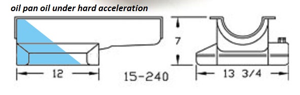
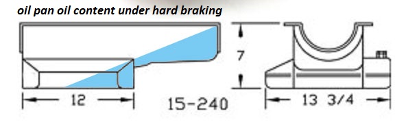
any less than about a 1/4" tends to restrict oil flow into the pick-up on many oil pump pick-up pan combo designs and more than about 3/8" to about 1/2 MAX tends to allow air to be sucked under some hard braking or acceleration with some pan and pick up designs so a 3/8"-1/2" pick-up to pan floor clearance is what I tend to try for, Ive seen numerious cases where a high volume pump was installed without checking the clearances (and of course the pick-up moved closer to the oil pan floor simply because the oil pump itself is longer and the pick ups deeper in the pan if its reused from the old pump)and the engine SEEMED to run out of oil pressure almost instantly on acceleration, (Im sure this is what leads to the myth of pumping the pan dry, but simply swapping pick-ups and verifying the pan floor to pick-up clearances cured the lack of oil flow into the pump and restriction that was the true cause of the low oil pressure condition.
remember the high volume pumps have a deeper body to fit the longer impeller gears. this places the oil pump pickup closer to the oil pan floor if no other changes are made when swapping to a high volume pump from the standard pump and can restrict oil flow into the pump
if you choose to install a high volume oil pump you should SERIOUSLY consider the fact that the pump is only a small part of the whole oil system,(which includes a high volume BAFFLED oil pan (7qts or more is ideal) and a windage screen, which is necessary to quickly return that extra oil to the sump, and doing the distributor mod is a big help, as it prevents any potential for cam/gear wear (something already almost non-existent with synthetic oil and the proper distributor gear material.)
the bye-pass spring only limits the pressure at which the bye-pass OPENS thus it only effects the upper pressure limit and has NOTHING to do with oil pressures or flow BELOW that level
BTW heres an old post that will answer several questions
I just got asked
" I just installed a new oil pump and have no oil pressure over about 1500rpm. but IM pulling about 24 psi at IDLE?? whats wrong GRUMPY"
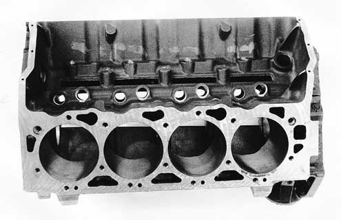
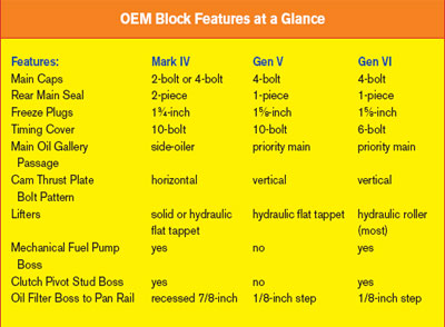
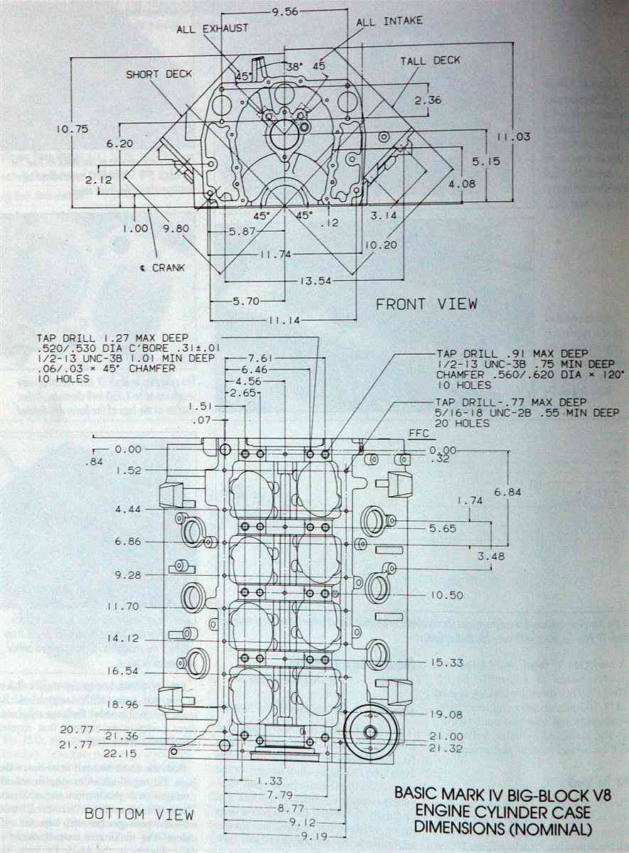
mark iv blocks
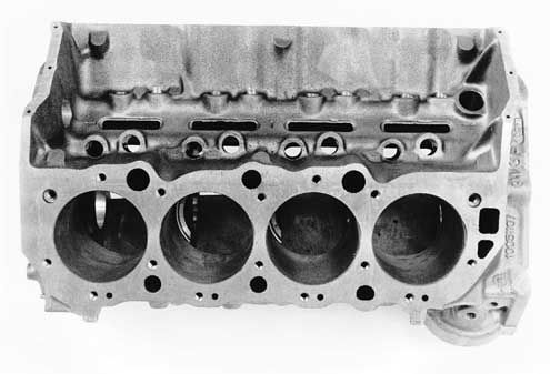
mark v blocks
(keep in mind that ALL '91 and later Gen.V and Gen.VI big blocks come with 4-bolt main caps. The two-bolt big blocks are no longer in production
MANY BUT NOT ALL aftermarket head designs have been modified to work on both the early MARK IV 1965-90 and later MARK V & VI blocks 1991-later.)
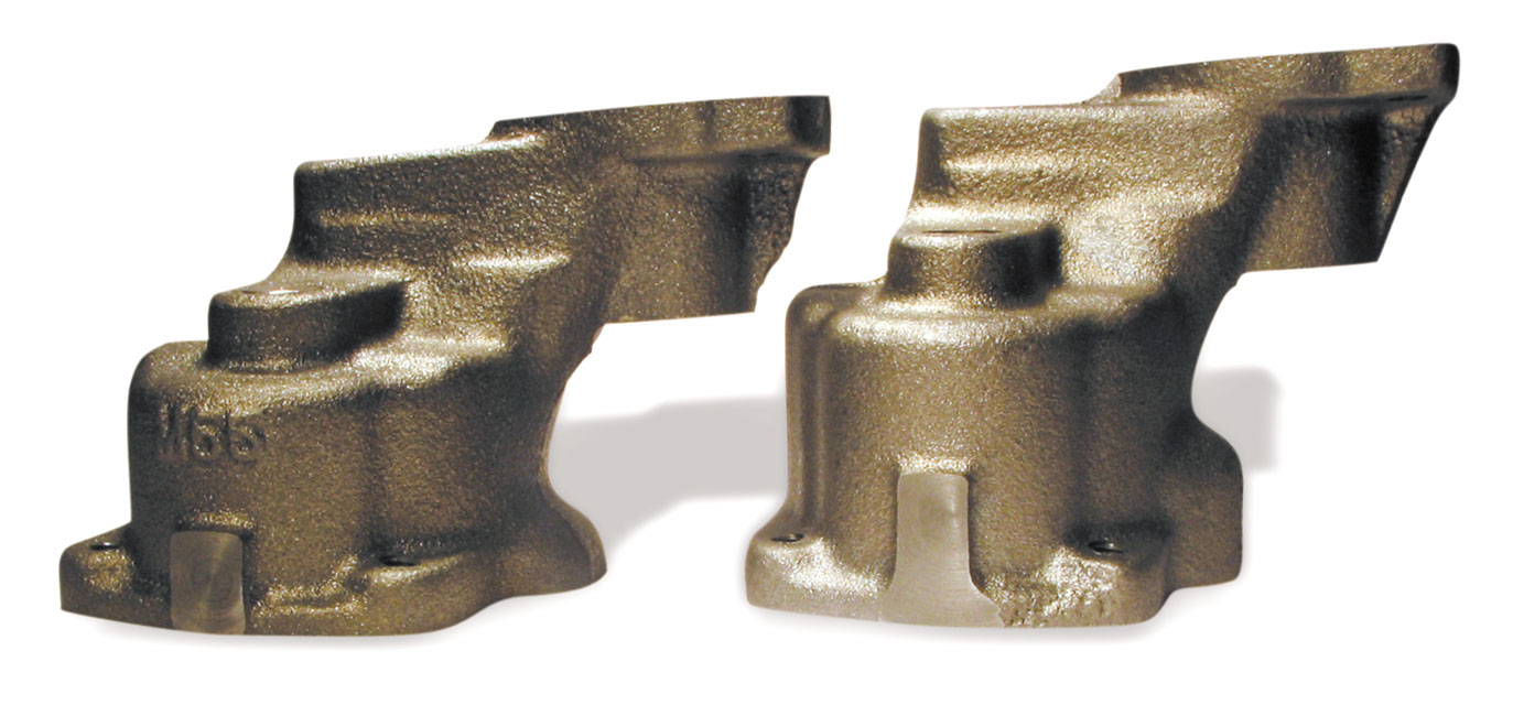
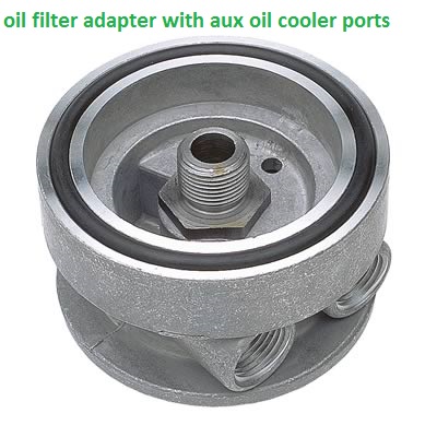
BTW, , on BIG BLOCKS the oil pumps and oil filter adapters are different due to the block oil filter recess and rear seals being different
GEN 4 or MARK IV
GEN V and VI
the oil pick-up needs to be mounted between 3/8-1/2" from the oil pan floor.MOUNT THE PUMPS INTAKE TOO CLOSE TOO THE PAN FLOOR AND YOU LL GET THE RESULTS YOUR SEEING! THE reason is that at low rpms the pumps pick-up can feed enough oil but speed up the pump, the flow requirement goes up and since the pick-up can,t supply the pumps needs, it sucks air and oil pressure falls rapidly to near ZERO ..until the rpms drop back to the point where the pick-up CAN supply the pumps needs
HERES MORE OIL INFO
small block oil pumps generally but not in all cases have 5/8" pickup tube dia. while BIG blocks generally but not in all cases have 3/4" pickup tube diam.
keep in mind that in many cases the big block pump can be bolted onto and used on the small block engine (a comon mod) and that you need to carefully check clearances on the oil pump,oil pump drive shaft to distributor length and pan to pickup clearances in all oil pump installations
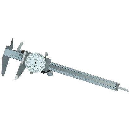
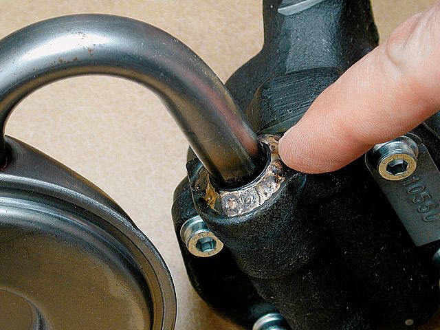
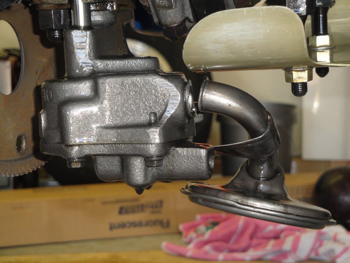
braze the pick-up tube to the pump body so the pick up is 3/8" MINIMUM, 1/2" maximum from the oil pan floor and use a large lump of MODELING CLAY (every mechanic should have some its great for checking clearances)on the pickup then install the pan temp. with no gasket and remove to measure the thickness of the clay
your local arts/craft store sells it in 1 lb blocks I usually use brite blue or black but suit your self, a digital caliper or even a ruler will get you the thickness measurement your looking for)
»http://store.yahoo.com/teacher-parent-store/modelingclay.html
http://www.guildcraftinc.com/ProductInfo.aspx?productid=102-500
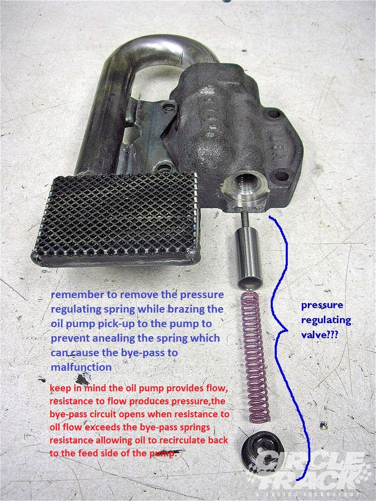
once its correctly positioned ,remove the bye pass spring and gears from the oil pump,and have the pick-up brazed or welded to the pump body, then after it SLOWLY AIR cools (DON,T DROP IT IN WATER LET IT AIR COOL)replace the bypass spring and gears, lube the pump,with assembly lube on the gears, check the clearances, check clearances again! and install! just be damn sure its brazed or welded in the correct location as that 3/8"-1/2" is critical to good oil volume feeding the pick-up
LSI/LS6 OIL ROUTING THRU BLOCK
worth reading
http://users.erols.com/jyavins/solder.htm«
http://www.tinmantech.com/html/faq_brazing_versus_soldering.html
http://www.epemag.wimborne.co.uk/solderfaq.htm
http://www.rehermorrison.com/techtalk/40.htm
silver soldering is basically lower temp brazing , the soldering metal flows over the surface and into micro cracks in the surface of the other metal forming a almost un-removeable bond to the other metals surface it allows you to stick iron to steel or brass to steel, it works more or less like normal solder does on copper but at higher temps and has a much stronger grip in addition too working on iron and steel
I vastly prefer the 5 BOLT BBC style pumps with the 12 tooth gears and their larger 3/4" pick-up VS the small 4 bolt pumps with their 5/8" pick-ups and 7 tooth gears. the oil flow is both higher pressure at low rpms and smoother in pulse pressure spread,no! you don,t need it on a non-race combo, or even on some race combos but its nice to have and I willingly will loose a few hp pumping oil for better engine lubrication
most common question I get? "will a high volume oil pump help or hurt my engine?" followed by some guy saying
"If you're using a stock capacity pan, the high volume oil pump could actually suck out all the oil from the pan before it is drained back in, thus creating bad, bad problems"
absolutely proven false bye SMOKE YUNICK with HIGH SPEED PHOTOGRAPHY and CLEAR WINDOWS IN ROCKER COVERS AND OIL PANbut what can and does happen is the oil pump pickup can and does get mounted or moved too high or low in the oil pan,restricting access to the oil supply, sometimes the pickup comes loose or under hard acceleration or braking the oil in a non-baffled pan can rush away from the pickup under (G) forces, this is not pumping the pan dry, a baffled pan with a windage screen with the same oil supply volume would work perfectly
ok lets look at a few things, pressure is the result of a resistance to flow , no matter how much oil is put out by the oil pump there is almost no pressure unless there is a resistance to that oil flow and the main resistance is from oil trying to flow through the bearing surface clearances and once the pumps output pressure exceeds the engines ability to accept the oilflow at the max pressure the oil return system/bypass spring allows the oil circles back through the pump ,now the amount of oil flow necessary to reach the furthest parts in the engine from the oil pump does not go up in direct relation to rpm, but it instead increases with rpm at a steadily increasing rate that increases faster than the engine rpm due to centrifugal force draining the oil from the rods as they swing faster and faster since energy increases with the square of the velocity the rate of oil use goes up quite a bit faster due to the greatly increased (G-FORCES) pulling oil from the rod bearings over 5000rpm going to 8000rpm than the rate of oil flow increases from 2000 rpm to 5000rpm (the same 3000rpm spread) and remember the often stated (10 lbs per 1000rpm)needs to be measured at the furthest rod and main bearing from the pump not at the pump itself, next lets look at the oil flow itself, you have about 5-6 quarts in an average small block now the valve covers never get and hold more than about 1/3 to 2/3 of a quart each even at 8000 rpm (high speed photography by SMOKEY YUNICK doing stock car engine research with clear plastic valve covers prove that from what Ive read) theres about 1 quart in the lifter gallery at max and theres about 1 quart in the filter and in the oil passages in the block, that leaves at least 2 quarts in the pan at all times and for those that want to tell me about oil wrapped around the crankshaft at high rpms try squirting oil on a spinning surface doing even 2000rpm (yes that's right its thrown off as fast as it hits by centrifugal force, yes its possible for the crankshaft WITHOUT A WINDAGE SCREEN to keep acting like a propeller and pulling oil around with it in the crank case but that's what the wrap around style milodon type windage screen is designed to stop)the only way to run out of oil is to start with less than 4 quarts or to plug the oil return passages in the lifter gallery with sludge or gasket material! now add a good windage tray and a crank scrapper and almost all the oil is returned to the sump as it enters the area of the spinning crankshaft! forming a more or less endless supply to the oil pump, BTW almost all pro teams now use DRY SUMP SYSTEMS WITH POSITIVE DISPLACEMENT GERATOR PUMPS that are 3,4,or 5 stage pumps each section of which has more volume than a standard volume oil pump because its been found total oil control is necessary at high rpms to keep bearings cool and lubed.
keep in mind both engine oil temps and trans fluid temps seldom reach operational temps,
and stabilize , for semi consistent data,in under 12-15 minutes of drive time.
NOW I POSTED THIS BEFORE BUT IT NEEDs REPEATING
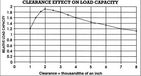
ok look at it this way,what your trying to do here is keep an pressurized oil film on the surface of all the bearings to lube and cool them and have enough oil spraying from the rod and main bearing clearances to lube the cam and cylinder walls/rings. now a standard pump does a good job up to 5000rpm and 400 hp but above 6000rpm and 400hp the bearings are under more stress and need more oil flow to cool and because the pressure on the bearings is greater you need higher pressures to maintain that oil film.lets look at the flow versus pressure curve. keep this in mind, good oil flow volume across the bearing surfaces to cool and lubricate them and to provide a boundary layer between the metal surfaces is more important than the pressure reached at all rpms. since oil is a liquid its non-compressible and flow will increase with rpm up to the point where the bypass circuit starts to re-route the excess flow at the point were the pressure exceeds the bypass spring pressure. but the volume will be equal to the pumps sweep volume times the rpm of the pump, since the high volume pump has a sweep volume 1.3-1.5 times the standard pump volume it will push 1.3-1.5 times the volume of oil up to the bypass circuit cut in point,that means that since the engine bearings leakage rate increases faster as the rpms increase because the clearances don,t change but the bleed off rate does that the amount of oil and the pressure that it is under will increase faster and reach the bypass circuit pressure faster with the high volume pump. the advantage here is that the metal parts MUST be floated on that oil film to keep the metal parts from touching/wearing and the more leakage points the oil flows by the less the volume of oil thats available for each leakage point beyond it and as the oil heats up it becomes easier to push through the clearances.now as the rpms and cylinder pressures increase in your goal to add power the loads trying to squeeze that oil out of those clearances also increase. ALL mods that increase power either increase rpms,cylinder pressures or reduce friction or mechanical losses. there are many oil leakage points(100) in a standard Chevy engine.
16 lifter to push rod points
16 push rod to rocker arm points
32 lifter bores 16 x 2 ends
10 main bearing edges
9 cam bearing edges
16 rod bearing edges
2 distributor shaft leaks
1 distributor shaft to shim above the cam gear(some engines that have an oil pressure feed distributor shaft bearing.)
so the more oil volume the better.Chevy did an excellent job in the design but as the stresses increase the cooling volume of the extra oil available from the larger pump helps to prevent lubrication delivery failure, do you need a better pump below 5000rpm or 400hp (hell no! at that level the stock pump works fine) above that level the extra oil will definitely help possible deficient oil flow and bearing cooling and a simple increase in pressure does not provide a big increase in volume that may be necessary to keep that oil film in the correct places at the correct volume at all times.the stock system was designed for a 265cid engine in a passenger car turning a max of about 6000 rpm but only having the stress of under 300hp transmitted to the bearings, Im sure the original designers never thought that the sbc or bbc would someday be asked to on occasion hold up to 450-800hp and 6000-8000 rpm. nor did they foresee valve springs that placed sometimes as much as 500lbs and up loads on the lifters and the use of over 9 to 1 compression ratios in the original design so the oil volumes and pressures necessary to cool those valve springs and bearings at those stress levels were never taken into account for that either , the stock pump works but was never designed for the loads and rpms that a modern engine hotrodded to over 450hp sees
the standard volume pump gears are about 1.2" long the high volume pump gears are about 1.5 inches long (depends on manufacturer)
heres the descriptions right from Chevy
12555884
SBC Oil Pump, High Pressure Z28/LT1. Production high-pressure oil pump with 1.20" gears.Will produce 60-70 psi oil pressure. Does not include screen. The pickup tube dia. is 5/8" for this pump.
62.17
14044872
SBC Oil Pump, High-Volume. This high-volume pump has1.50" long gears.It has approximately 25% more capacity than a production pump at standard pressure. Does not include screen.
and yes I comonly build small blocks useing bbc oil pumps like the ls7 pump, it has 1.3" gears but they are bigger in dia. and have 12 not 7 teethlike the small block pumps (many standard sbc pickups use 5/8" dia. pickups) (the ls7 pump is best used on 8qt-9qt road racing oilpans as the larger 3/4" pickup flows lots of oil for extreme high rpm engines with a multi baffled pan using windage screens, scrappers and cut outs for extreme (G) loads where a dry sump can,t be used or cost makes you stick to a wet sump pan. these LS7 pumps don't fit most sbc oil pans so your stuck using the high volume sbc oil pump if your not using a true racing 8-9 qt style oil pan in some cases
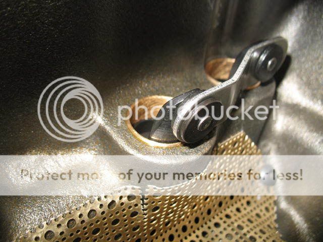
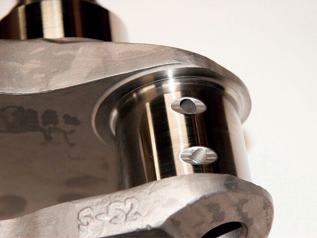
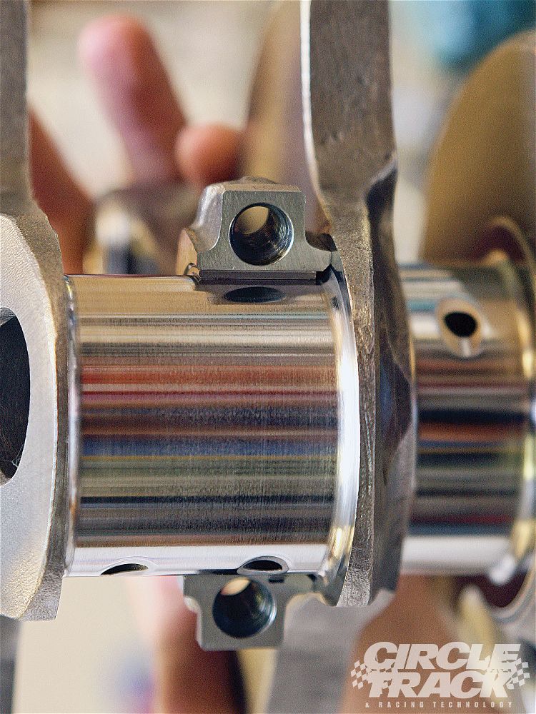
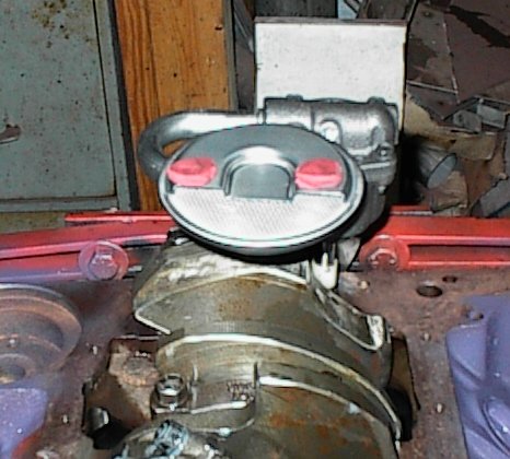
since I just got an E-MAIL about what mods are necessary or at least a good idea when running a high volume oil pump, and concern over possible extra gear wear caused by the slightly and I do mean slightly increased pressure on the gears, guys Im getting the idea here that most of you are not aware that your normally suppose to cut a .060 wide x .005-9 deep groove in the lower band on the distributor housing so that extra oil sprays constantly on the contact point between the cam and distributor gears and that a ARP style drive shaft with a steel collar to hold the drive shaft alignment on true center is mandatory for long high rpm use. look at this picture:
The groove is cut under the bottom (O)ring in the band just above the gear (look at the picture above, (BTW the pic shows a smaller groove than ideal)) and in line with the gears so that oil sprays on the gear contact points at all times, this is a mod most old time racers know about and use, but Im getting the idea the new guys have not picked up on it! (those two bands form the side of an oil passage in the block and the distributor shaft seals that passage, cutting the groove sends a spray of high pressure oil onto the contact point at all times, if you don't cut the groove your relieing on returning zero pressure oil flowing down the rear lifter gallery drain holes to lube the gears
BTW the other way to do this is to groove the block in the distributors lower band area as this keeps the location of the oil jet constant as the distributor is turned, for a full contact spray on the gears so I generally do BOTH
btw
heres more OIL info
http://motorcycleinfo.calsci.com/Oils1.html
http://minimopar.knizefamily.net/oilfilterstudy.html
http://www.unofficialbmw.com/all/misc/all_oilfaq.html
http://www.bobistheoilguy.com/
http://www.babcox.com/editorial/ar/ar10180.htm
http://www.melling.com/support/bulletins/default.asp
http://www.melling.com/select/oil_pumps_gm_chevy_small_block.asp
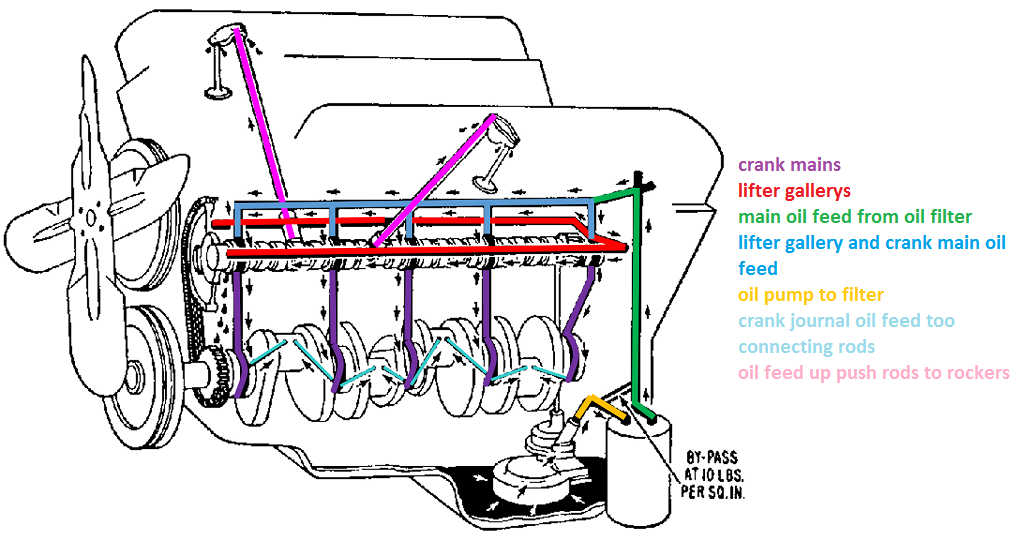
theres three potential GATES or valves in the oil flow path thru the blocks oil passages, the pump provides oil flow, and a bye-pass valve internal to the pump limiting max oil pressure to the spring resistance selected (usually 60-75 psi)
many oil filters have an ANTI-DRAIN BACK VALVE
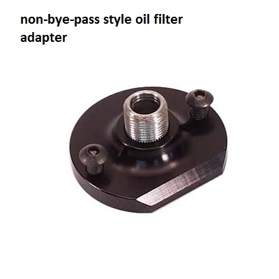
many oil filter adapters have a oil filter bye-pass valve, that opens if the resistance to oil flow exceeds 10 psi
viewtopic.php?f=54&t=3536
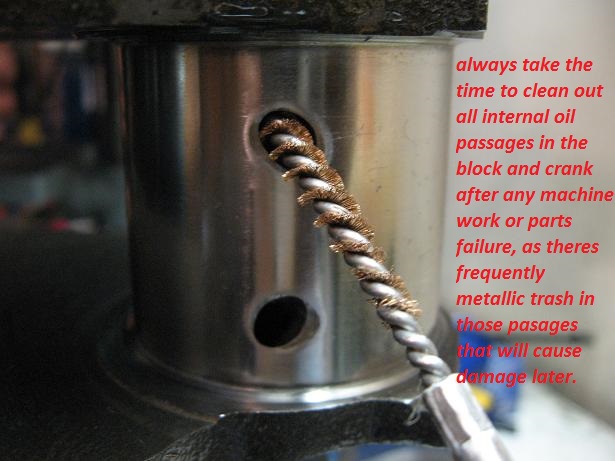
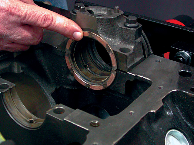
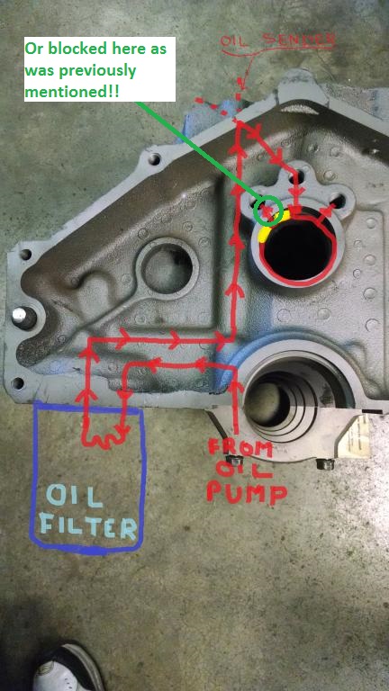
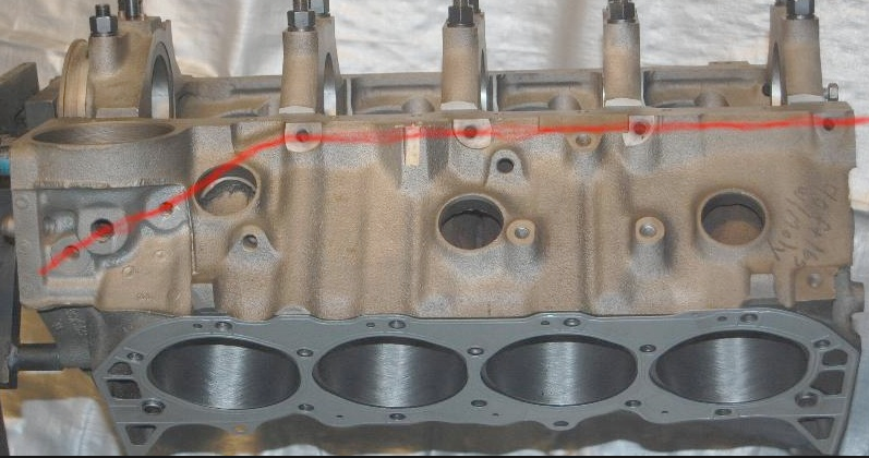
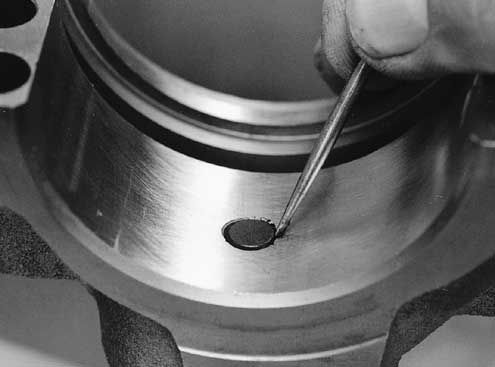
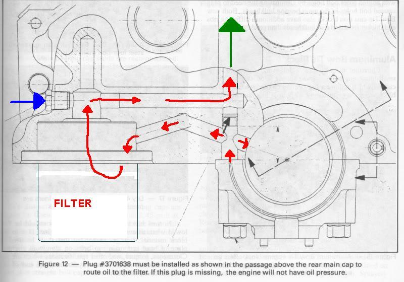
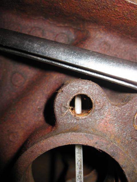
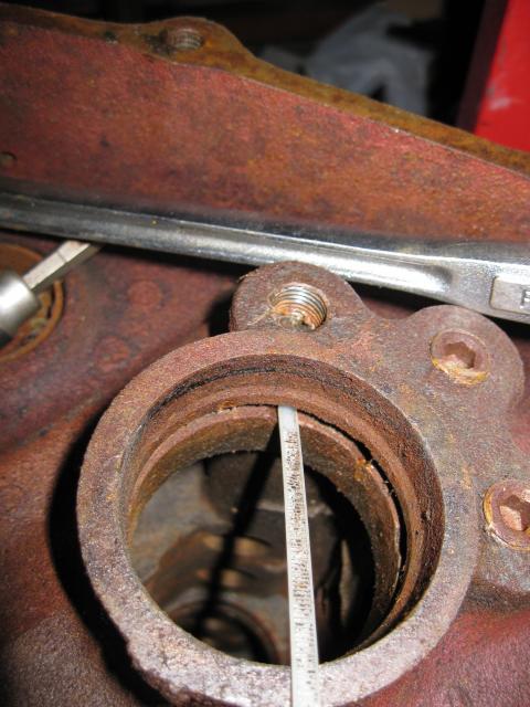
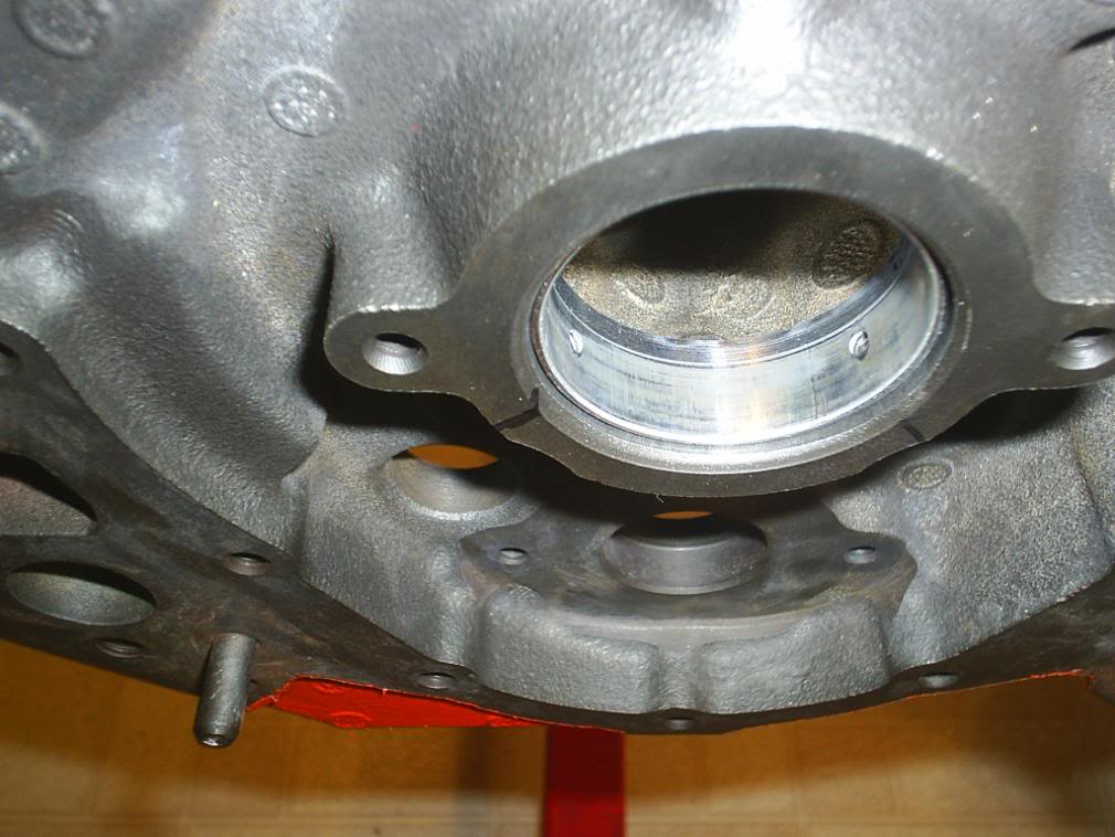
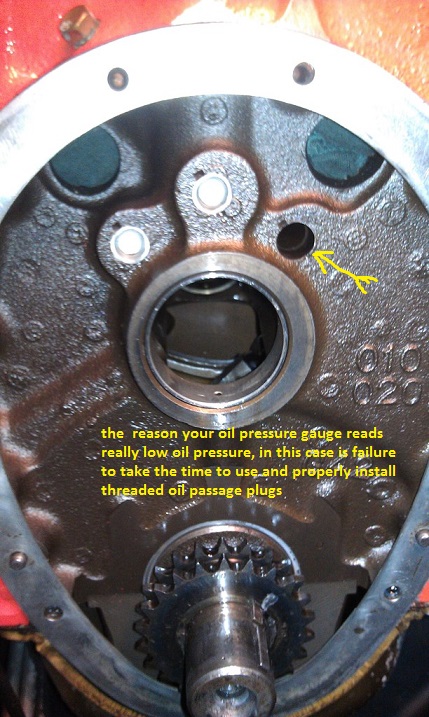
Don’t forget the “forgotten†plug. If you don’t remove it before the block is cleaned, debris can hide in the main oil passages. And if you forget to reinstall it before the rear main cap is bolted on, oil will not be directed through the oil filter!
BTW THATS NOT TOTALLY TRUE! YOU STILL HAVE SOME OIL PRESSURE BUT MOST OF THE OIL BYE_PASSES THE OIL FILTER

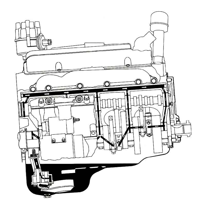
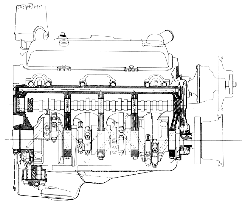
first gen small block oiling
LSI/LS6 OIL ROUTING THRU BLOCK
[ img]http://www.sallee-chevrolet.com/Engine_Blocks/images/12480157.gif[/img]
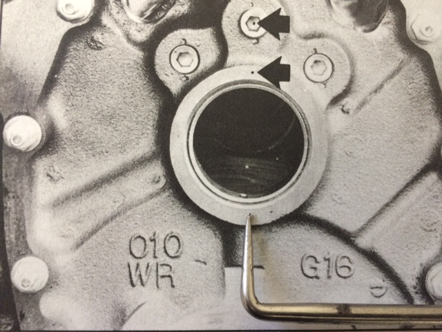
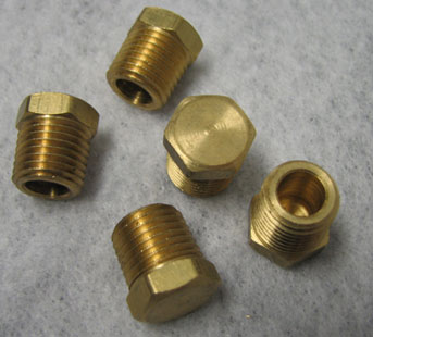
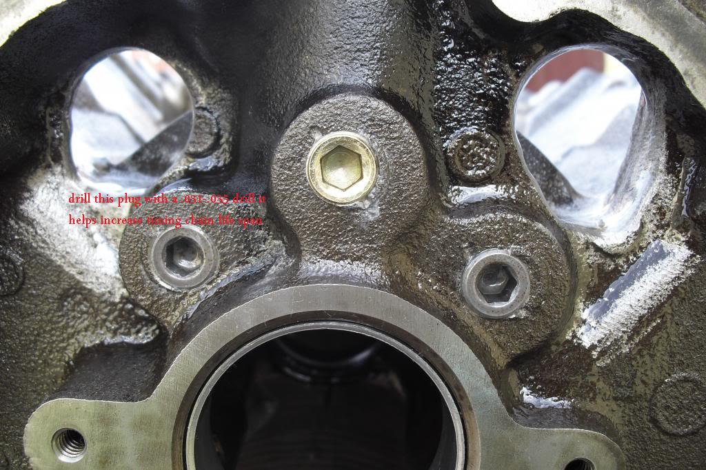
one or at the most two of outer plugs for the oil passages plugs above the cam, drill a .030-.038 hole in one or both , naturally the one on the left is preferred as the rotation favors that side for spraying oil everywhere under the timing cover
BTW DRILL the removed oil passage plugs, while they are clamped between a couple boards with a drill press If you can, you don,t want metallic shavings in the engine
don,t get too wrapped up in worrying about which oil is superior, keep in mind oils main function is to provide a lubricating film and transfer absorbed heat,away from the moving parts, almost ANY of the name brand oils do that well and ALMOST ANY oil will last at least 5000 miles without significant loss of its abilities to do that if the filters used keep the particles in it minimized AND the temp stays in the 190F-250F range. but like I stated earlier, oil needs to get up to 215F at least for a short time to burn off moisture, and above about 240F it slowly brakes down, its the regular replacement with clean oil , to remove the crud from the engine and good filters that's the key!
EVEN if you had the best oil in the world, that could easily last 30K-35K miles the CRUD & acids trapped in the oil from combustion,would cause wear and reduce its lubrication abilities over time, if the filters don,t remove the majority of that crud the oils life expectancy is limited regardless of the oil quality itself , and regular replacement is the key
a few pictures above may help
http://www.digitalcorvettes.com/forums/showthread.php?t=80781
http://www.hotrod.com/articles/ccrp-0911-small-block-chevy-oil-pumps/
https://www.chevydiy.com/1955-1996-chevy-small-block-performance-guide-oiling-system-manual-part-9/
a high volume pump has slightly longer gears, usually about 10%-20% longer, that build the volume of oil pushed thru the engines oil passages,and engines clearances 10%-20% faster at any given rpm, PRESSURE is a measure of resistance to oil flow thru those clearances, theres a bye-pass circuit in the pump designed to open and limit the pressure at a set pressure level, that's usually 60-65 psi in a high volume pump and at 65-70 psi in a high pressure pump, theres no real disadvantage unless the pumps bye-pass circuit is not functioning correctly and starts to restrict the flow and the pressure builds to higher levels than intended resulting in resistance to the pump which adds drag and eats hp.
theres no lubrication increase past about 55-60 psi of oil flow thru the bearing clearances so the idea is to match the oils viscosity to the engine clearances at the engines operational temperature and to use an oil cooler and the engines oil bye-pass circuit to maintain the pressure and temperature within known, and predicted limits.
HERES SOME USEFUL INFO, that might help in this thread and the sub links
http://garage.grumpysperformance.com/index.php?threads/crank-case-blow-bye-and-related-info.16790/
the first thing Id be doing here, if your not getting a strong oil flow at each rocker while your turn the engine manually and use the oil priming tool, is carefully visual checking of BOTH the valve train rocker geometry and that the push rods are completely hollow and free of debris, by cleaning each with solvent and high pressure air, then mocking the drive train up and verifying that BOTH the rocker and push rod oil feed holes line up at some point in the 720 degrees of rotation, and that the bottom end of the push rods stay aligned with the center of the lifters, seat, this might sound like its a assumed fact, but its easily possible for the push rods to bind on the push rod guide plates or guide slots in the cylinder heads, this potential BINDING will move the push rod , out of its seat on the lifter or rocker preventing proper oil feed out of the lifter or rockers proper alignment, if the oil feed holes are not properly lined up oil won't flow freely.
the oil mist bath, being constantly thrown from the rotating crank assembly unto the lower bore walls,and rockers over the valve train,valve springs, rockers,rods and underside of the pistons does A GREAT DEAL of the initial heat absorption and heat transfer,
and prevents the pistons and rings from being damaged,
only as the hot oil falls, and drains back into the lower sump is much of the heat transferred to the coolant in the block.
oil flow and coolant flow are both required to absorb and remove heat build-up from the engine,especially from the rotating assembly , bearings,and valve train components
http://www.chevyhiperformance.com/techa ... index.html
http://www.melling.com/Aftermarket/Tech-Tip-Videos
http://www.mellingengine.com/TechnicalS ... etins.aspx
viewtopic.php?f=54&t=3536
Chevrolet Performance 14091563
Left (Driver Side) Dipstick Plug
Chevrolet Performance 9421743
Right (Passenger Side) Dipstick Plug
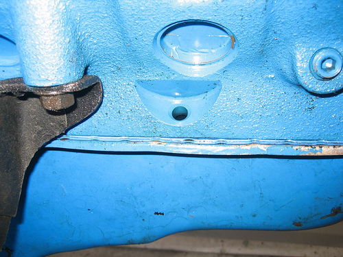
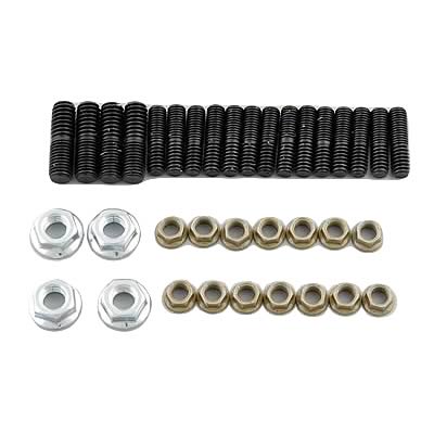
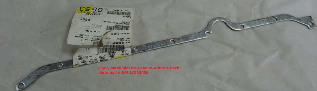
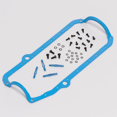
On oil pans I prefer studs, and an oil pan back plate
you might want to Use with P/N 12553058 RH and P/N 12553059 LH oil pan reinforcement plates to distribute the bolt stress on the oil pan rail for 1985 and earlier oil pans P/N 14088501 (LH) and P/N 14088502 (RH).1986 and newer
thats a very common question but the answers no!
ALL THAT OIL FILTER BYE-PASS VALVE DOES IS ROUTE OIL FLOW PAST THE OIL FILTER
IF IT BECOMES SO CLOGGED WITH TRASH THAT THERES
A 10 PSI DIFFERENCE IN THE RESISTANCE TO OIL FLOW THROUGH THE FILTER
VS AROUND IT INTO THE BLOCKS OIL PASSAGES, oil enters the area over the oil filter in the block and is forced into the outer holes in the oil filter perimeter down through the case and filter element and up through the central hollow screw retention stud into the blocks oil passages, if the resistance too flow is too great the oil filter bye-pass valve routes oil around the filter directly from oil pump to the blocks oil passages.
MORE USEFUL INFO
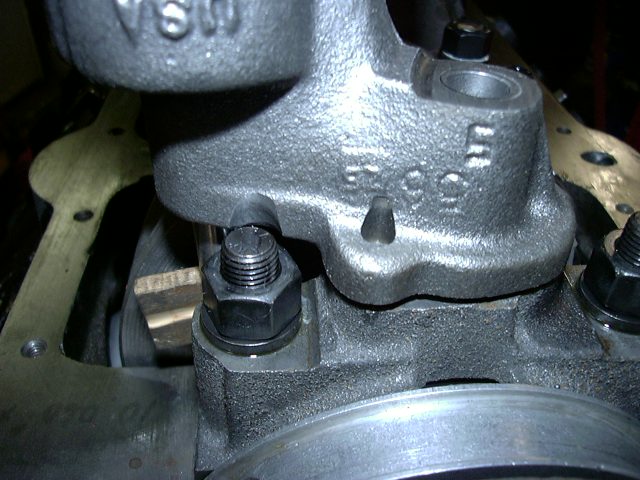
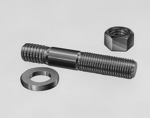
yes the oil flows around the mounting stud,from oil pump to main cap to reach the engine oil passages, thru the oil filter
failure to use the correct oil pump,mounting stud, bolt or nut or carefully check clearances when mounting an oil pump can cause problems
ONE RATHER COMMON MISTAKE IS USING THE WRONG OIL PUMP STUD OR BOLT TO MOUNT THE OIL PUMP AS IF EITHER EXTENDS THRU THE REAR MAIN CAP IT CAN AND WILL BIND ON THE BEARING AND LOCK OR RESTRICT, SMOOTH ROTATION
http://garage.grumpysperformance.co...-friction-and-pumping-losses.8966/#post-31978
viewtopic.php?f=54&t=4537
http://www.improvedracing.com/tech/LS-o ... nsions.php
http://www.stevesnovasite.com/forums/sh ... p?t=208618
http://www.enginebuildermag.com/2018/06/performance-oiling-systems-2/
http://ls1tech.com/forums/conversions-h ... -pans.html
viewtopic.php?f=52&t=788
http://www.nonlintec.com/sprite/oil_myths.pdf
pressure is a measure of RESISTANCE to oil flow, if the pumps providing flow and yes that needs to be verified,
( because if the oil pump pick-up is less than a 1/4" off the oil pan floor flow is potentially restricted)
if your getting oil flow from the oil pump and no back pressure Id suggest checking the flow control valves, bearing clearances and oil passage plugs at the ends of the lifter gallery passages, any major open to flow oil passage results in very low oil pressure readings
http://garage.grumpysperformance.co...ark-v-bbc-engine-oil-system-differences.4576/
https://www.chevydiy.com/oil-lubrication-systems-guide-big-block-chevy-engines/
https://paceperformance.com/i-51345...ich-adapter-for-external-oil-cooler-only.html
http://garage.grumpysperformance.com/index.php?threads/basic-info-on-your-v8-lube-system.52/
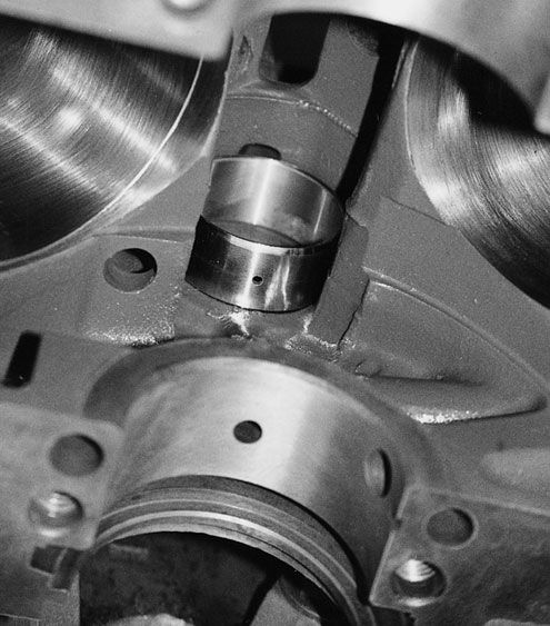
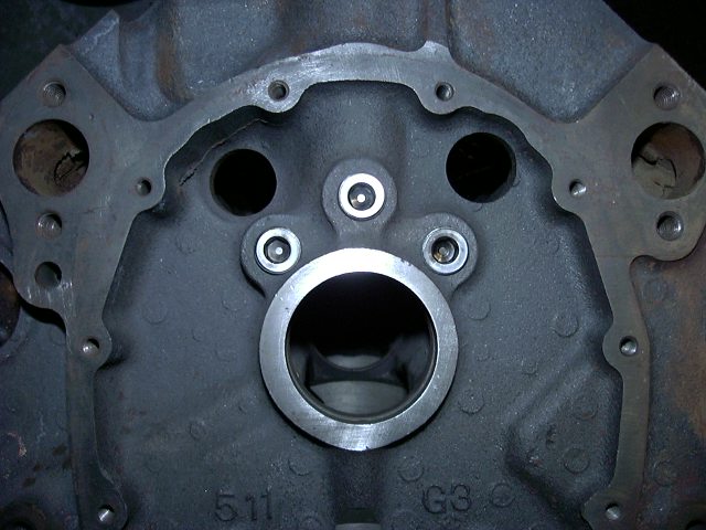
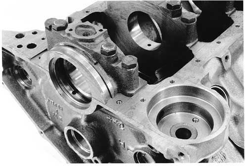
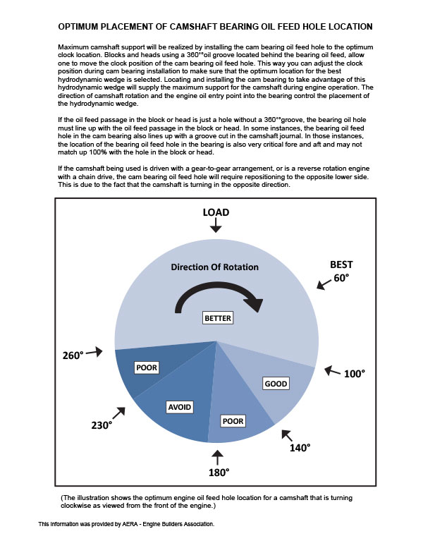
Big Block Chevrolet Gen V and Gen VI Oiling SystemSolving the mystery of the Gen V and Gen VI Priority Main Oiling system
Priority Main Oiling System
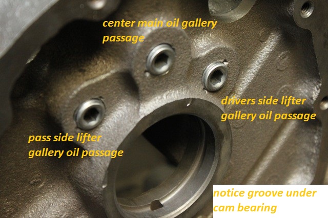
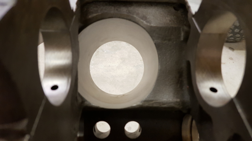
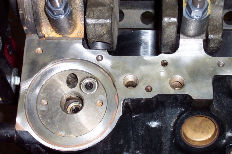
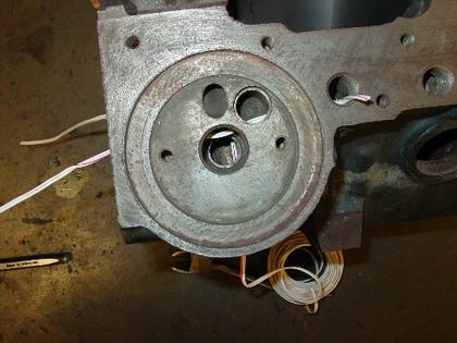
The Generation V and VI big block Chevrolet blocks feature a priority main oiling system where the main oil supply passage is located adjacent to the camshaft tunnel. Drilled passages which intersect this large oil tunnel carry oil directly to the main bearings. If you are facing the front of the block with the engine in the upright position, this main oil supply tunnel is located in the 2 o’clock position just below the right hand lifter oil supply line.
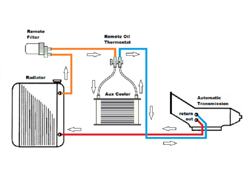
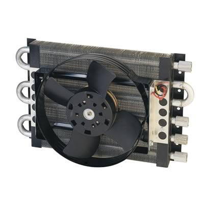
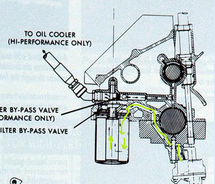
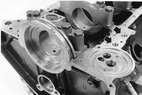
Oil Cooler Plumbing
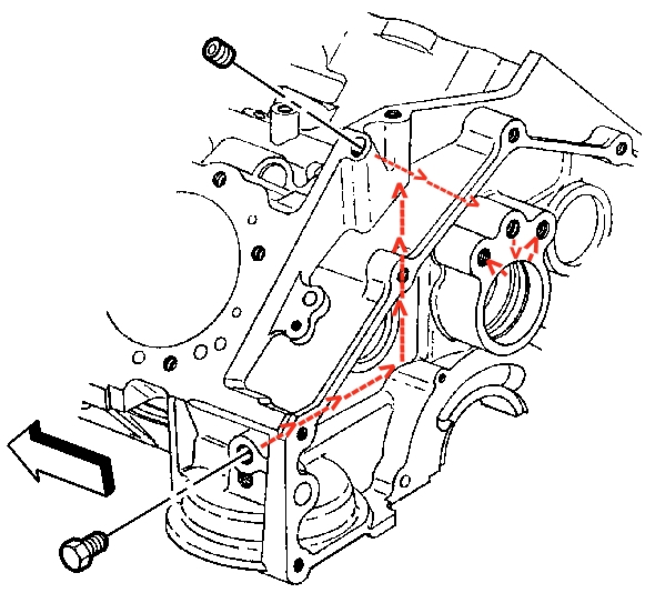
Located along the oil pan rail just ahead of the oil filter pad are two drilled and tapped (3/8” NPT) oil passages for routing oil to an external oil cooler. The hole located closest to the oil filter pad (#2) is for the outgoing supply line to the oil cooler. The front passage (#1), which is farthest from the filter pad, is the return line from the oil cooler.
Careful examination reveals that these two passages intersect the same return line that feeds oil back to the main oil tunnel. This requires that a special fitting be used in the #2 supply line to prevent oil from short circuiting the oil cooler.
Part number SD1540 provides the necessary diverter basket to prevent the supply oil from entering the return line before going to the oil cooler. This fitting has a dash 10AN thread to allow the use of aftermarket components to plumb your external oil cooler. The front passage #1 will require a 3/8” NPT by dash 10AN adapter (#FCM2185), which is available from Scoggin-Dickey.
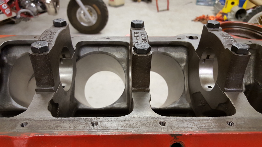
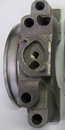
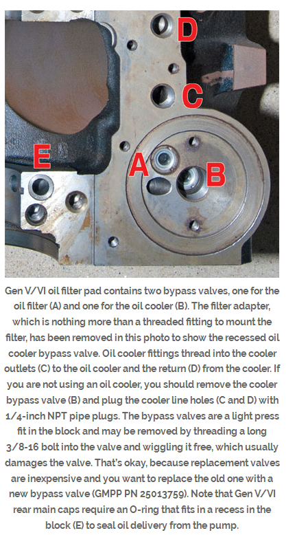
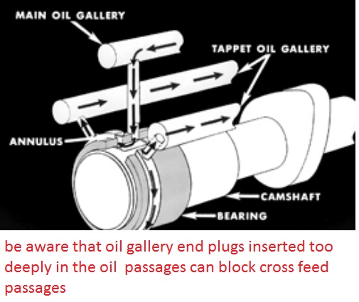
Understanding By-pass Valve Locations
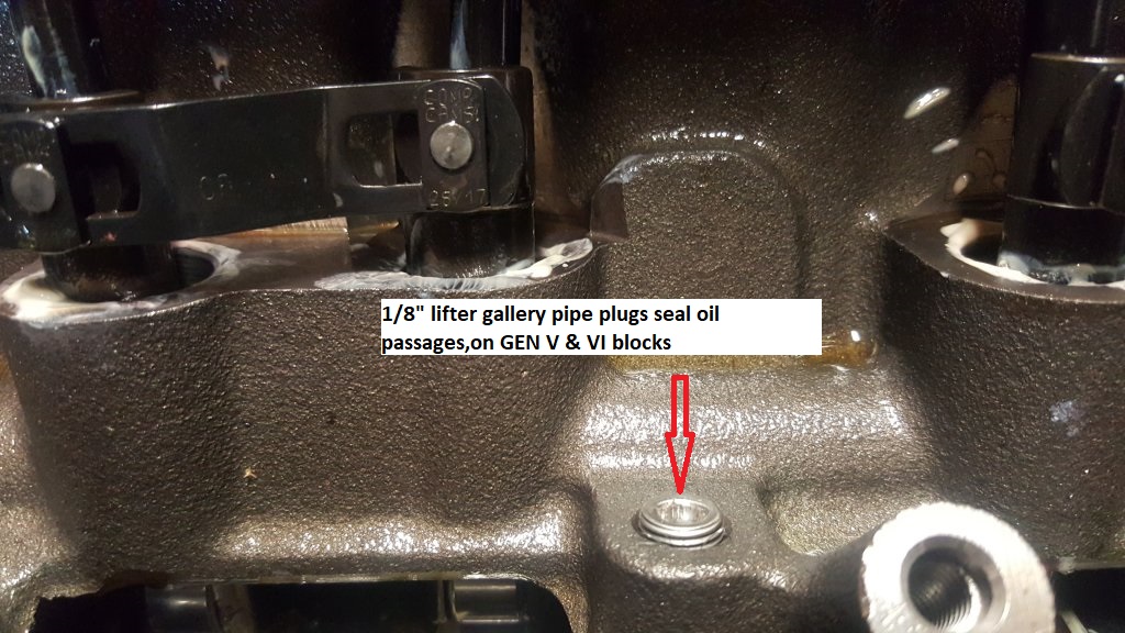
Factory assembled 454, 502 engines and short blocks have two by-pass valves installed in the block. These factory installed by-pass valves (#25013759) will open at an 11 psi pressure differential. One by-pass valve is installed in the center hole on the oil filter pad (#4). This hole is the oil return passage from the oil filter. The second by-pass valve is installed in the adjacent hole (#3). The egg shaped hole (#5) is the high pressure oil supply passage from the oil pump.
For all racing application that will NOT use an oil cooler but will maintain the stock oil filter location, you must remove the center by-pass valve in location #4. Removing this valve eliminates three redundant right runs in the oil system. However, if you leave this by-pass in place the oil system will still function as it was intended, but a loss of oil pressure can result from the four right angle turns required for oil to return to the main oil tunnel.
If you intend to use a remote oil filter, a high pressure by-pass valve part number 25161284 must be installed in position #3. This valve will open at a 30 psi pressure differential. A plug will be installed in position #4 to prevent oil flow thru this passage. Oil should be returned to the block in the 3/8” hole located just able the oil filter pad. An oil filter block off plate kit (#SD3891) can be purchased from Scoggin-Dickey for Gen V and VI blocks to plumb your external oil filter.
If you intend to maintain the stock filter location and will use the factory provided oil cooler passages to install your oil cooler, then you must install two high pressure by-pass valves (#25161284). One will be installed in location #3 and the second in location #4.
https://www.chevydiy.com/oil-lubrication-systems-guide-big-block-chevy-engines/
use this oil pump(link below) in most stock SBC builds, as it produces a 10% increase in oil volume and standard pressure which is just fine , but obviously check your bearing clearances and oil pump to oil pan floor clearances and braze the CORRECT MATCHING pick-up to the pump, and I,d also suggest if you have the room, for clearance that you look into one of the less expensive 7 quart baffled oil pans as they provide a good deal more potential protection and durability to your bearings longevity. be very sure you verify the oil pump pick-up to oil pan floor clearance, and braze the pick-up to the pump body.
yes theres less expensive oil pumps that will work, but thats a good value, in a well made pump.
first choice
http://www.summitracing.com/parts/mel-10552/overview/ SBC
or
http://www.jegs.com/i/Melling/689/10778C/10002/-1 BBC
second choice
http://www.summitracing.com/parts/mil-18750/overview/ SBC
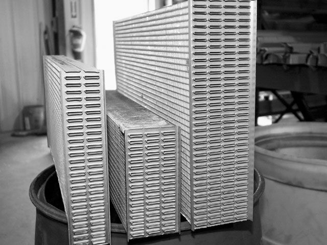
ADDING A WELL DESIGNED WINDAGE SCREEN SPEEDS OIL RETURN SPEEDS . AND EFFICIENCY TO THE ENGINE SUMP
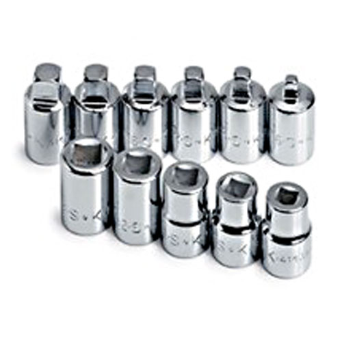
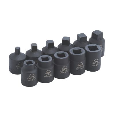
keep in mind the sbc oil pump has 7 tooth gears and the big block pumps have 12 teeth making the oil flow smoother and less pulsed, plus having larger gears they tend to supply more oil at lower rpms
look closely and youll see the big block oil pump has a 5 bolt lower cover and the oil pump pick-up with its 3/4" feed seats into the main pump casting while the small block oil pump has a 4 bolt cover and the sbc oil pump pick-up with its 5/8" feed seats into the pumps cover plate
Id also point out that its virtually impossible , in a well designed engine to run the engine "long enough to pump all the oil upstairs."[/img]
as with a properly designed baffled oil pan, with a carefully fitted and clearanced windage screen and crank scraper, the oil pump simply reaches a flow rate pumping oil out of about 100 or so potential lubricant flow leakage points
OIL PRESSURE read on the oil pressure gauge is a MEASURE of RESISTANCE to oil flow, you can REDUCE the pressure the gauge reads by either increasing the engine clearances or REDUCING the oil viscosity (thickness) so it flows thru the clearances faster with less resistance.(OR INSTALLING A SLIGHTLY WEAKER OIL PUMP BYE_PASS SPRING,that limits the pump pressure before it allows some oil to re-circulate back through the bye-pass valve ,from the high pressure back to the low pressure side of the pump impellers, but only the max pressure you reach is limited by the bye-pass spring,in your oil pressure bye pass circuit and its that spring resistance determines the point where the bye-pass circuit, opens and limits max oil pressure, but the bye-pass circuit has zero to do with anything else, if its functioning correctly,
there are many oil leakage points(100) in a standard Chevy engine.
16 lifter to push rod points
16 push rod to rocker arm points
32 lifter bores 16 x 2 ends
10 main bearing edges
9 cam bearing edges
16 rod bearing edges
2 distributor shaft leaks
1 distributor shaft to shim above the cam gear(some engines that have an oil pressure feed distributor shaft bearing.)
once oil exits the bearings or valve train it flows mostly by gravity back to the oil pan sump, but a properly designed windage screen and crank scraper correctly clearanced allows the spinning crank/rotating assembly to act like a directional pump that drags the vast majority of the oil flow back to the sump, by design.
your 55 psi at idle serves no purpose as 15psi-25psi is all thats expected in a new engine with tight clearances using a good 10W30 oil, if your using a higher viscosity than 10w30 its reducing oil flow rates and reducing heat transfer rates, Id suggest using a good 10W30 oil. and use of a 7-8 quart, baffled oil pan and windage tray
(NOTICE ITS A 4 BOLT small BLOCK HIGH VOLUME OIL PUMP WITH A 5/8" pickup}
10553
10553High pressure performance upgrade for M-55 & M-55A.
Standard volume oil pump.
The 10553 housing and cover are CNC machined and phosphate coated.
Manufactured with pink spring installed for higher pressure (M-55A).
To change pump to lower pressure (M-55) install the supplied yellow spring.
Includes intermediate shaft with steel guide.
The 10553 uses a 5/8” press in screen.
10552
High volume performance oil pump.
10% increase in volume over stock oil pump.
The 10552 is manufactured with the drive and idler shafts extended to allow for additional support in the cover eliminating dynamic shaft deflection at increased RPM levels.
The cover is doweled to the pump housing to assure alignment of the shaft bores.
Screw in plug retains relief valve spring instead of pin.
Relief hole in cover uses screw in plug instead of pressed cup plug.
All bolts are self locking socket heads, with the wrench supplied.
The housing and cover are CNC machined and phosphate coated.
Includes intermediate shaft with steel guide. Uses both 3/4” bolt on or press in screen.
The lower pressure spring is included to reduce pressure if desired.
Patent No. 5,810,571.
10778C (Anti-Cavitation)
(NOTICE ITS A 5 BOLT BIG BLOCK HIGH VOLUME OIL PUMP WITH A 3/4" pickup}
http://www.summitracing.com/parts/mel-10778
High volume performance upgrade for the 10770.
Increase in volume of 25% over stock oil pump.
The same as the 10778 except with the addition of grooves machined in the housing and cover. The grooves reduce cavitation effects in high RPM applications.
Using this oil pump will reduce pressure at idle.
Includes intermediate shaft with steel guide.
Uses 3/4” press in screen.
Racing applications only.
Patent No. 5,810,571
from chevy high performance mag
keep in mind that as oil temps increase the oil viscosity tends to decrease, thus cold oil, at lets say 70F might cause the oil pressure gauge to read 50 psi at idle but the pressure reading slowly goes down to 25 psi once the oils reached lets say 210F, this is normal and expected
you might want to read thru these links and sub links,
as theres a great deal of related useful info contained
viewtopic.php?f=54&t=3536
viewtopic.php?f=54&t=2187
viewtopic.php?f=54&t=2102
viewtopic.php?f=54&t=64
viewtopic.php?f=54&t=1334
(1)pressure is the measure of resistance to oil flow
If you decrease the viscosity to a lighter oil, you tend to increase flow at a loss of pressure. High flow helps to carry away more bearing heat at a faster rate, but it must be balanced with the pressure levels, High pressure helps to keep metal parts like the crank and rod bearings out of direct contact with each other as they are separated by a film of supporting oil (scuffing).â€
(2) the high volume pump can push about 25% more oil , high flow rates result in more heat transferred from bearings, and rockers and valves ETC. to the oil flowing thru the clearances
(3) the oil pump bye-pass circuit limits the max pressure in either size pump to about 65lbs-75 lbs MAXIMUM before it BYE-PASSES enough additional oil volume to limit the pressure
(4) the engine can accept and use only the max flow volume that the engine passages, and clearances can flow at the max pressure the pump provides , at any point less than max pressure the passages can flow only what the pressure and volume provided by the pump supplies
(5)if the bearing clearances can flow more than the pump provides in volume and pressure at any rpm level the film of cooling oil that provides a cushion between the bearing surfaces are at risk of not being supported and separated by that cushion of flowing oil
(6) now since the sweep volume is greater with the high volume pump it will reach that bye-pass circuits max pressure at about 25% lower rpms and supply a POTENTIALLY higher volume of oil to the supply passages/bearings
(7)SO... all a high volute pump does is provide the maximum oil flow the engine can use up to the max pressure allowed by the bye-pass circuit at a 25% lower rpm level if the system can reach max pressure, but it also supplies 25% more oil at every rpm level below that point to provide additional cooling and protection for the engine. and if the engine can flow more than the stock pump can provide the high volume pump helps fill the need faster
(8)oil flow through the bearing clearances INCREASES at a faster rate as the rpms increase
(9) in most engines the oil flow can be provided by the stock pump IF the clearances are close to stock AND THE RPM LEVELS ARE KEPT IN ABOUT THE idle-6000rpm range but if rpm levels exceed ABOUT 6000rpm,or if bearing loads greatly exceed the stock hp levels, or the clearances are greater than stock, the high volume pump is a good idea , simply because it potentially provides that extra volume of oil.
(10) you generally want to run the THINNEST VISCOSITY oil that will maintain about 20-25 psi at operation temps at about 1000rpm, to provide the maximum flow rates, and check the rest of the threads info, synthetics tend to have higher temperature tolerances
there are oil pump testers available commercially or if your mechanically inclined you can fabricate one with reasonable care, after a bit of measuring and purchasing a gauge
http://cvrproducts.com/oil-pressure-test-kit/
any less than about a 1/4" tends to restrict oil flow into the pick-up on many oil pump pick-up pan combo designs and more than about 3/8" to about 1/2 MAX tends to allow air to be sucked under some hard braking or acceleration with some pan and pick up designs so a 3/8"-1/2" pick-up to pan floor clearance is what I tend to try for, Ive seen numerious cases where a high volume pump was installed without checking the clearances (and of course the pick-up moved closer to the oil pan floor simply because the oil pump itself is longer and the pick ups deeper in the pan if its reused from the old pump)and the engine SEEMED to run out of oil pressure almost instantly on acceleration, (Im sure this is what leads to the myth of pumping the pan dry, but simply swapping pick-ups and verifying the pan floor to pick-up clearances cured the lack of oil flow into the pump and restriction that was the true cause of the low oil pressure condition.
remember the high volume pumps have a deeper body to fit the longer impeller gears. this places the oil pump pickup closer to the oil pan floor if no other changes are made when swapping to a high volume pump from the standard pump and can restrict oil flow into the pump
if you choose to install a high volume oil pump you should SERIOUSLY consider the fact that the pump is only a small part of the whole oil system,(which includes a high volume BAFFLED oil pan (7qts or more is ideal) and a windage screen, which is necessary to quickly return that extra oil to the sump, and doing the distributor mod is a big help, as it prevents any potential for cam/gear wear (something already almost non-existent with synthetic oil and the proper distributor gear material.)
the bye-pass spring only limits the pressure at which the bye-pass OPENS thus it only effects the upper pressure limit and has NOTHING to do with oil pressures or flow BELOW that level
BTW heres an old post that will answer several questions
I just got asked
" I just installed a new oil pump and have no oil pressure over about 1500rpm. but IM pulling about 24 psi at IDLE?? whats wrong GRUMPY"
mark iv blocks
mark v blocks
(keep in mind that ALL '91 and later Gen.V and Gen.VI big blocks come with 4-bolt main caps. The two-bolt big blocks are no longer in production
MANY BUT NOT ALL aftermarket head designs have been modified to work on both the early MARK IV 1965-90 and later MARK V & VI blocks 1991-later.)
BTW, , on BIG BLOCKS the oil pumps and oil filter adapters are different due to the block oil filter recess and rear seals being different
GEN 4 or MARK IV
GEN V and VI
the oil pick-up needs to be mounted between 3/8-1/2" from the oil pan floor.MOUNT THE PUMPS INTAKE TOO CLOSE TOO THE PAN FLOOR AND YOU LL GET THE RESULTS YOUR SEEING! THE reason is that at low rpms the pumps pick-up can feed enough oil but speed up the pump, the flow requirement goes up and since the pick-up can,t supply the pumps needs, it sucks air and oil pressure falls rapidly to near ZERO ..until the rpms drop back to the point where the pick-up CAN supply the pumps needs
HERES MORE OIL INFO
small block oil pumps generally but not in all cases have 5/8" pickup tube dia. while BIG blocks generally but not in all cases have 3/4" pickup tube diam.
keep in mind that in many cases the big block pump can be bolted onto and used on the small block engine (a comon mod) and that you need to carefully check clearances on the oil pump,oil pump drive shaft to distributor length and pan to pickup clearances in all oil pump installations
braze the pick-up tube to the pump body so the pick up is 3/8" MINIMUM, 1/2" maximum from the oil pan floor and use a large lump of MODELING CLAY (every mechanic should have some its great for checking clearances)on the pickup then install the pan temp. with no gasket and remove to measure the thickness of the clay
your local arts/craft store sells it in 1 lb blocks I usually use brite blue or black but suit your self, a digital caliper or even a ruler will get you the thickness measurement your looking for)
»http://store.yahoo.com/teacher-parent-store/modelingclay.html
http://www.guildcraftinc.com/ProductInfo.aspx?productid=102-500
once its correctly positioned ,remove the bye pass spring and gears from the oil pump,and have the pick-up brazed or welded to the pump body, then after it SLOWLY AIR cools (DON,T DROP IT IN WATER LET IT AIR COOL)replace the bypass spring and gears, lube the pump,with assembly lube on the gears, check the clearances, check clearances again! and install! just be damn sure its brazed or welded in the correct location as that 3/8"-1/2" is critical to good oil volume feeding the pick-up
LSI/LS6 OIL ROUTING THRU BLOCK
worth reading
http://users.erols.com/jyavins/solder.htm«
http://www.tinmantech.com/html/faq_brazing_versus_soldering.html
http://www.epemag.wimborne.co.uk/solderfaq.htm
http://www.rehermorrison.com/techtalk/40.htm
silver soldering is basically lower temp brazing , the soldering metal flows over the surface and into micro cracks in the surface of the other metal forming a almost un-removeable bond to the other metals surface it allows you to stick iron to steel or brass to steel, it works more or less like normal solder does on copper but at higher temps and has a much stronger grip in addition too working on iron and steel
I vastly prefer the 5 BOLT BBC style pumps with the 12 tooth gears and their larger 3/4" pick-up VS the small 4 bolt pumps with their 5/8" pick-ups and 7 tooth gears. the oil flow is both higher pressure at low rpms and smoother in pulse pressure spread,no! you don,t need it on a non-race combo, or even on some race combos but its nice to have and I willingly will loose a few hp pumping oil for better engine lubrication
most common question I get? "will a high volume oil pump help or hurt my engine?" followed by some guy saying
"If you're using a stock capacity pan, the high volume oil pump could actually suck out all the oil from the pan before it is drained back in, thus creating bad, bad problems"
absolutely proven false bye SMOKE YUNICK with HIGH SPEED PHOTOGRAPHY and CLEAR WINDOWS IN ROCKER COVERS AND OIL PANbut what can and does happen is the oil pump pickup can and does get mounted or moved too high or low in the oil pan,restricting access to the oil supply, sometimes the pickup comes loose or under hard acceleration or braking the oil in a non-baffled pan can rush away from the pickup under (G) forces, this is not pumping the pan dry, a baffled pan with a windage screen with the same oil supply volume would work perfectly
ok lets look at a few things, pressure is the result of a resistance to flow , no matter how much oil is put out by the oil pump there is almost no pressure unless there is a resistance to that oil flow and the main resistance is from oil trying to flow through the bearing surface clearances and once the pumps output pressure exceeds the engines ability to accept the oilflow at the max pressure the oil return system/bypass spring allows the oil circles back through the pump ,now the amount of oil flow necessary to reach the furthest parts in the engine from the oil pump does not go up in direct relation to rpm, but it instead increases with rpm at a steadily increasing rate that increases faster than the engine rpm due to centrifugal force draining the oil from the rods as they swing faster and faster since energy increases with the square of the velocity the rate of oil use goes up quite a bit faster due to the greatly increased (G-FORCES) pulling oil from the rod bearings over 5000rpm going to 8000rpm than the rate of oil flow increases from 2000 rpm to 5000rpm (the same 3000rpm spread) and remember the often stated (10 lbs per 1000rpm)needs to be measured at the furthest rod and main bearing from the pump not at the pump itself, next lets look at the oil flow itself, you have about 5-6 quarts in an average small block now the valve covers never get and hold more than about 1/3 to 2/3 of a quart each even at 8000 rpm (high speed photography by SMOKEY YUNICK doing stock car engine research with clear plastic valve covers prove that from what Ive read) theres about 1 quart in the lifter gallery at max and theres about 1 quart in the filter and in the oil passages in the block, that leaves at least 2 quarts in the pan at all times and for those that want to tell me about oil wrapped around the crankshaft at high rpms try squirting oil on a spinning surface doing even 2000rpm (yes that's right its thrown off as fast as it hits by centrifugal force, yes its possible for the crankshaft WITHOUT A WINDAGE SCREEN to keep acting like a propeller and pulling oil around with it in the crank case but that's what the wrap around style milodon type windage screen is designed to stop)the only way to run out of oil is to start with less than 4 quarts or to plug the oil return passages in the lifter gallery with sludge or gasket material! now add a good windage tray and a crank scrapper and almost all the oil is returned to the sump as it enters the area of the spinning crankshaft! forming a more or less endless supply to the oil pump, BTW almost all pro teams now use DRY SUMP SYSTEMS WITH POSITIVE DISPLACEMENT GERATOR PUMPS that are 3,4,or 5 stage pumps each section of which has more volume than a standard volume oil pump because its been found total oil control is necessary at high rpms to keep bearings cool and lubed.
keep in mind both engine oil temps and trans fluid temps seldom reach operational temps,
and stabilize , for semi consistent data,in under 12-15 minutes of drive time.
NOW I POSTED THIS BEFORE BUT IT NEEDs REPEATING
ok look at it this way,what your trying to do here is keep an pressurized oil film on the surface of all the bearings to lube and cool them and have enough oil spraying from the rod and main bearing clearances to lube the cam and cylinder walls/rings. now a standard pump does a good job up to 5000rpm and 400 hp but above 6000rpm and 400hp the bearings are under more stress and need more oil flow to cool and because the pressure on the bearings is greater you need higher pressures to maintain that oil film.lets look at the flow versus pressure curve. keep this in mind, good oil flow volume across the bearing surfaces to cool and lubricate them and to provide a boundary layer between the metal surfaces is more important than the pressure reached at all rpms. since oil is a liquid its non-compressible and flow will increase with rpm up to the point where the bypass circuit starts to re-route the excess flow at the point were the pressure exceeds the bypass spring pressure. but the volume will be equal to the pumps sweep volume times the rpm of the pump, since the high volume pump has a sweep volume 1.3-1.5 times the standard pump volume it will push 1.3-1.5 times the volume of oil up to the bypass circuit cut in point,that means that since the engine bearings leakage rate increases faster as the rpms increase because the clearances don,t change but the bleed off rate does that the amount of oil and the pressure that it is under will increase faster and reach the bypass circuit pressure faster with the high volume pump. the advantage here is that the metal parts MUST be floated on that oil film to keep the metal parts from touching/wearing and the more leakage points the oil flows by the less the volume of oil thats available for each leakage point beyond it and as the oil heats up it becomes easier to push through the clearances.now as the rpms and cylinder pressures increase in your goal to add power the loads trying to squeeze that oil out of those clearances also increase. ALL mods that increase power either increase rpms,cylinder pressures or reduce friction or mechanical losses. there are many oil leakage points(100) in a standard Chevy engine.
16 lifter to push rod points
16 push rod to rocker arm points
32 lifter bores 16 x 2 ends
10 main bearing edges
9 cam bearing edges
16 rod bearing edges
2 distributor shaft leaks
1 distributor shaft to shim above the cam gear(some engines that have an oil pressure feed distributor shaft bearing.)
so the more oil volume the better.Chevy did an excellent job in the design but as the stresses increase the cooling volume of the extra oil available from the larger pump helps to prevent lubrication delivery failure, do you need a better pump below 5000rpm or 400hp (hell no! at that level the stock pump works fine) above that level the extra oil will definitely help possible deficient oil flow and bearing cooling and a simple increase in pressure does not provide a big increase in volume that may be necessary to keep that oil film in the correct places at the correct volume at all times.the stock system was designed for a 265cid engine in a passenger car turning a max of about 6000 rpm but only having the stress of under 300hp transmitted to the bearings, Im sure the original designers never thought that the sbc or bbc would someday be asked to on occasion hold up to 450-800hp and 6000-8000 rpm. nor did they foresee valve springs that placed sometimes as much as 500lbs and up loads on the lifters and the use of over 9 to 1 compression ratios in the original design so the oil volumes and pressures necessary to cool those valve springs and bearings at those stress levels were never taken into account for that either , the stock pump works but was never designed for the loads and rpms that a modern engine hotrodded to over 450hp sees
the standard volume pump gears are about 1.2" long the high volume pump gears are about 1.5 inches long (depends on manufacturer)
heres the descriptions right from Chevy
12555884
SBC Oil Pump, High Pressure Z28/LT1. Production high-pressure oil pump with 1.20" gears.Will produce 60-70 psi oil pressure. Does not include screen. The pickup tube dia. is 5/8" for this pump.
62.17
14044872
SBC Oil Pump, High-Volume. This high-volume pump has1.50" long gears.It has approximately 25% more capacity than a production pump at standard pressure. Does not include screen.
and yes I comonly build small blocks useing bbc oil pumps like the ls7 pump, it has 1.3" gears but they are bigger in dia. and have 12 not 7 teethlike the small block pumps (many standard sbc pickups use 5/8" dia. pickups) (the ls7 pump is best used on 8qt-9qt road racing oilpans as the larger 3/4" pickup flows lots of oil for extreme high rpm engines with a multi baffled pan using windage screens, scrappers and cut outs for extreme (G) loads where a dry sump can,t be used or cost makes you stick to a wet sump pan. these LS7 pumps don't fit most sbc oil pans so your stuck using the high volume sbc oil pump if your not using a true racing 8-9 qt style oil pan in some cases
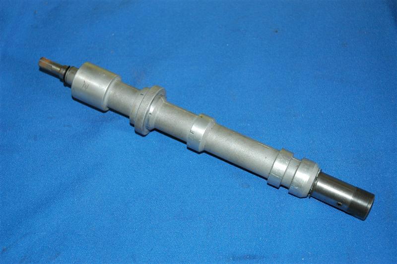
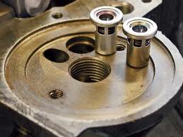
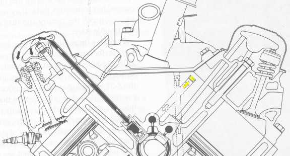
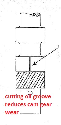
since I just got an E-MAIL about what mods are necessary or at least a good idea when running a high volume oil pump, and concern over possible extra gear wear caused by the slightly and I do mean slightly increased pressure on the gears, guys Im getting the idea here that most of you are not aware that your normally suppose to cut a .060 wide x .005-9 deep groove in the lower band on the distributor housing so that extra oil sprays constantly on the contact point between the cam and distributor gears and that a ARP style drive shaft with a steel collar to hold the drive shaft alignment on true center is mandatory for long high rpm use. look at this picture:
The groove is cut under the bottom (O)ring in the band just above the gear (look at the picture above, (BTW the pic shows a smaller groove than ideal)) and in line with the gears so that oil sprays on the gear contact points at all times, this is a mod most old time racers know about and use, but Im getting the idea the new guys have not picked up on it! (those two bands form the side of an oil passage in the block and the distributor shaft seals that passage, cutting the groove sends a spray of high pressure oil onto the contact point at all times, if you don't cut the groove your relieing on returning zero pressure oil flowing down the rear lifter gallery drain holes to lube the gears
BTW the other way to do this is to groove the block in the distributors lower band area as this keeps the location of the oil jet constant as the distributor is turned, for a full contact spray on the gears so I generally do BOTH
btw
heres more OIL info
http://motorcycleinfo.calsci.com/Oils1.html
http://minimopar.knizefamily.net/oilfilterstudy.html
http://www.unofficialbmw.com/all/misc/all_oilfaq.html
http://www.bobistheoilguy.com/
http://www.babcox.com/editorial/ar/ar10180.htm
http://www.melling.com/support/bulletins/default.asp
http://www.melling.com/select/oil_pumps_gm_chevy_small_block.asp
theres three potential GATES or valves in the oil flow path thru the blocks oil passages, the pump provides oil flow, and a bye-pass valve internal to the pump limiting max oil pressure to the spring resistance selected (usually 60-75 psi)
many oil filters have an ANTI-DRAIN BACK VALVE
many oil filter adapters have a oil filter bye-pass valve, that opens if the resistance to oil flow exceeds 10 psi
viewtopic.php?f=54&t=3536
Don’t forget the “forgotten†plug. If you don’t remove it before the block is cleaned, debris can hide in the main oil passages. And if you forget to reinstall it before the rear main cap is bolted on, oil will not be directed through the oil filter!
BTW THATS NOT TOTALLY TRUE! YOU STILL HAVE SOME OIL PRESSURE BUT MOST OF THE OIL BYE_PASSES THE OIL FILTER
first gen small block oiling
LSI/LS6 OIL ROUTING THRU BLOCK
[ img]http://www.sallee-chevrolet.com/Engine_Blocks/images/12480157.gif[/img]
one or at the most two of outer plugs for the oil passages plugs above the cam, drill a .030-.038 hole in one or both , naturally the one on the left is preferred as the rotation favors that side for spraying oil everywhere under the timing cover
BTW DRILL the removed oil passage plugs, while they are clamped between a couple boards with a drill press If you can, you don,t want metallic shavings in the engine
don,t get too wrapped up in worrying about which oil is superior, keep in mind oils main function is to provide a lubricating film and transfer absorbed heat,away from the moving parts, almost ANY of the name brand oils do that well and ALMOST ANY oil will last at least 5000 miles without significant loss of its abilities to do that if the filters used keep the particles in it minimized AND the temp stays in the 190F-250F range. but like I stated earlier, oil needs to get up to 215F at least for a short time to burn off moisture, and above about 240F it slowly brakes down, its the regular replacement with clean oil , to remove the crud from the engine and good filters that's the key!
EVEN if you had the best oil in the world, that could easily last 30K-35K miles the CRUD & acids trapped in the oil from combustion,would cause wear and reduce its lubrication abilities over time, if the filters don,t remove the majority of that crud the oils life expectancy is limited regardless of the oil quality itself , and regular replacement is the key
a few pictures above may help
http://www.digitalcorvettes.com/forums/showthread.php?t=80781
http://www.hotrod.com/articles/ccrp-0911-small-block-chevy-oil-pumps/
https://www.chevydiy.com/1955-1996-chevy-small-block-performance-guide-oiling-system-manual-part-9/
a high volume pump has slightly longer gears, usually about 10%-20% longer, that build the volume of oil pushed thru the engines oil passages,and engines clearances 10%-20% faster at any given rpm, PRESSURE is a measure of resistance to oil flow thru those clearances, theres a bye-pass circuit in the pump designed to open and limit the pressure at a set pressure level, that's usually 60-65 psi in a high volume pump and at 65-70 psi in a high pressure pump, theres no real disadvantage unless the pumps bye-pass circuit is not functioning correctly and starts to restrict the flow and the pressure builds to higher levels than intended resulting in resistance to the pump which adds drag and eats hp.
theres no lubrication increase past about 55-60 psi of oil flow thru the bearing clearances so the idea is to match the oils viscosity to the engine clearances at the engines operational temperature and to use an oil cooler and the engines oil bye-pass circuit to maintain the pressure and temperature within known, and predicted limits.
Last edited by a moderator:


 many pumps come with two springs , one standard and one high pressure you should NEVER shim an oil pumps pressure relief spring back in the 1950s-1960s it was common to pull the pressure...