1 cubic foot of air at standard temperature and pressure assuming average composition weighs approximately 0.0807 lbs. (at sea level)
that simply means it takes 12.4 cubic feet of air to equal one pound,
your best engine torque is generally found at a fuel/air ratio near 12.6:1 ,
thats 12.6 pounds of air per pound of fuel.
now lets do some math,
remember the intake stroke is only every other revolution,
lets say you built a 454 chevy engine, 454/8+ 56.75 cubic inches per cylinder.
theres 1728 cubic inches of air in a cubic foot,
thus it takes a single cylinder rotating about 61 revolutions,
to ingest a cubic foot of air,
but of course its a V8 ,
so in reality your looking at about 7.62 revolutions to ingest
that cubic foot of air. (assuming near 100% efficiency)
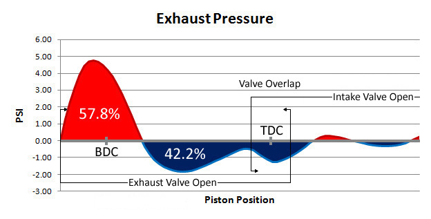
which can only be achieved with good exhaust scavenging
and correct matched cam timing,
free lowing exhaust and of course decent heads and intake designs
 the days of easy access too $.34 cents a gallon SUNOCO 260 are unfortunately now just a distant,
but pleasant memory
but E85 has some significantly increased octane potential if your willing to deal with some issues
think about that, every 7.62 revolutions it sucks in nearly 1 cubic foot of air, if we assume most nearly stock engines idle at about 800 rpm...your looking at the engine at idle ingesting about 105 cubic feet of air every minute at idle speeds. at 6500 rpm, your looking at about 853 cubic feet of air ingested near peak rpms
853 cubic feed of air volume about 1 lb of fuel per 12.6 lbs of air,it takes 12.4 cubic feet of air to equal one pound, that would require about 5.45 lbs of fuel
per minute at peak rpms.
gasoline generally weights near 6 lbs per gallon, so at peak power a 454 could potentially burn almost a 9/10th of a gallon per minute.
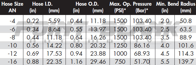
that also means that the fuel delivery system must keep up with demand, so in the example above I would suggest nothing less than a fuel system fully capable of providing about 75-80 gallons per hour (remember even if your fuel pump can theoretically deliver 100 gph, theres flow losses in the fittings filters and lines so Id advise a fuel delivery with line sized 3/8" minimum and ideally a full 1/2" inside diameter on any serious muscle car application )
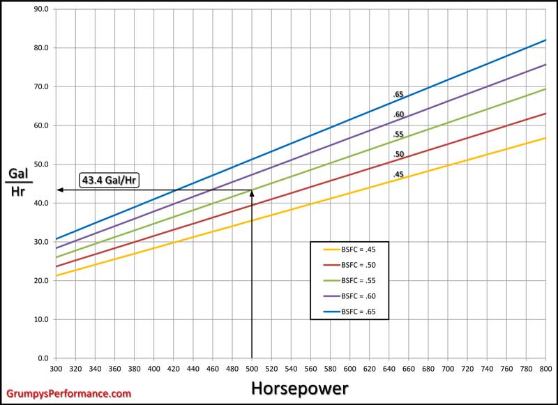
Given Horsepower x .50 lb fuel/hp = lbs of fuel for given horsepower
To calculate Fuel Consumption for a 400 hp Gas engine with a BSFC of .50 lbs/hp/hr:
400 hp x .50 = 200 lbs/hr
To convert this lbs/hr to a more meaningful gallons per hour we use the conversion rate from lbs to gallons which is 6.2 lbs to 1 gallon of gas
200 lbs/hr / 6.2 lbs/gal = 32.25 gph
BSFC .50 / 6.2 = .0806 gallons / horsepower / hour.
Again we calculate Fuel Consumption for a 400 hp Gas engine.
400 hp x .0806 = 32.24 gph
Remember, if you are running E85 or Methanol be sure to use those BSFC values in your formula. To calculate peak fuel consumption for a 800 hp E-85 engine we can use a BSFC of .70 and the formulas below.
800 hp x .70 = 560 lbs/hr 560 lbs/hr / 6.2 lbs/gal = 90.32 gph
OR
BSFC .70 / 6.2 = .113 gallons / horsepower / hour
800 * .113 = 90.40 gph
Note: These gph flow rates may seem high when compared to your daily driver on the highway, but remember these are not averages, these are flow at loaded peak output.
USE THE CALCULATORS to match port size to intended rpm levels... but keep in mind valve lift and port flow limitations
http://www.wallaceracing.com/runnertorquecalc.php
http://www.wallaceracing.com/ca-calc.php
http://www.wallaceracing.com/area-under-curve.php
http://www.wallaceracing.com/chokepoint.php
http://www.wallaceracing.com/header_length.php
http://www.circletrack.com/enginetech/1 ... ch_engine/
https://performancedevelopments.com/fuel-flow-calculations-for-horsepower/
http://blog.cantonracingproducts.com/blog/how_to_estimate_your_engines_fuel_flow
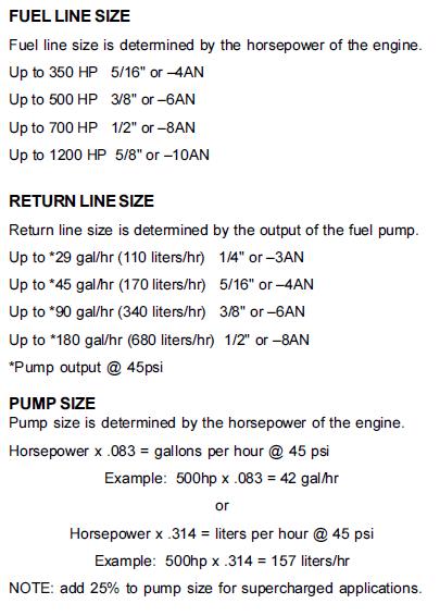
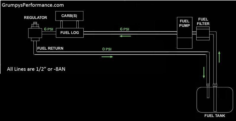
be aware that the cross sectional area of both the fuel lines and fuel filter medium,
and the fuel pressure regulator and return line cross sectional area all effect the fuel delivery efficiency
and fuel delivery consistency is critical,, you need a certain, dependable,
fuel volume available, pressure increases only go so far in correcting lack of required fuel delivery issues,
and you might get by with a cars stock 3/8" lines on a dyno , but once your dealing with inertial loads,
and longer duration, high power runs a 3/8" line is usually hopeless on a 750-1000 hp engine
http://garage.grumpysperformance.com/index.php?threads/setting-up-your-fuel-system.211/#post-26636
http://garage.grumpysperformance.co...-big-a-fuel-pump-do-you-need.1939/#post-21738
http://garage.grumpysperformance.co...e-required-octane-for-compression-ratio.2718/
related info
http://garage.grumpysperformance.co...e-required-octane-for-compression-ratio.2718/
http://garage.grumpysperformance.com/index.php?threads/calculate-fuel-injector-size.1200/
http://garage.grumpysperformance.com/index.php?threads/how-big-a-fuel-pump-do-you-need.1939/
http://garage.grumpysperformance.co...engine-volumetric-efficiency.6254/#post-55061
http://garage.grumpysperformance.com/index.php?threads/intake-runner-question.12899/
https://www.raceworks.com.au/calculators/injector-hp-calculator/
http://garage.grumpysperformance.co...es-restrict-fuel-flow-rates.12859/#post-66683
http://garage.grumpysperformance.co...ss-fuel-pressure-regulators.12776/#post-65998
http://garage.grumpysperformance.com/index.php?threads/bits-of-427-bbc-build-related-info.15543/
http://garage.grumpysperformance.co...-sizing-return-vs-feed.3067/page-3#post-61157
that simply means it takes 12.4 cubic feet of air to equal one pound,
your best engine torque is generally found at a fuel/air ratio near 12.6:1 ,
thats 12.6 pounds of air per pound of fuel.
now lets do some math,
remember the intake stroke is only every other revolution,
lets say you built a 454 chevy engine, 454/8+ 56.75 cubic inches per cylinder.
theres 1728 cubic inches of air in a cubic foot,
thus it takes a single cylinder rotating about 61 revolutions,
to ingest a cubic foot of air,
but of course its a V8 ,
so in reality your looking at about 7.62 revolutions to ingest
that cubic foot of air. (assuming near 100% efficiency)
which can only be achieved with good exhaust scavenging
and correct matched cam timing,
free lowing exhaust and of course decent heads and intake designs
but pleasant memory
but E85 has some significantly increased octane potential if your willing to deal with some issues
think about that, every 7.62 revolutions it sucks in nearly 1 cubic foot of air, if we assume most nearly stock engines idle at about 800 rpm...your looking at the engine at idle ingesting about 105 cubic feet of air every minute at idle speeds. at 6500 rpm, your looking at about 853 cubic feet of air ingested near peak rpms
853 cubic feed of air volume about 1 lb of fuel per 12.6 lbs of air,it takes 12.4 cubic feet of air to equal one pound, that would require about 5.45 lbs of fuel
per minute at peak rpms.
gasoline generally weights near 6 lbs per gallon, so at peak power a 454 could potentially burn almost a 9/10th of a gallon per minute.
that also means that the fuel delivery system must keep up with demand, so in the example above I would suggest nothing less than a fuel system fully capable of providing about 75-80 gallons per hour (remember even if your fuel pump can theoretically deliver 100 gph, theres flow losses in the fittings filters and lines so Id advise a fuel delivery with line sized 3/8" minimum and ideally a full 1/2" inside diameter on any serious muscle car application )
Given Horsepower x .50 lb fuel/hp = lbs of fuel for given horsepower
To calculate Fuel Consumption for a 400 hp Gas engine with a BSFC of .50 lbs/hp/hr:
400 hp x .50 = 200 lbs/hr
To convert this lbs/hr to a more meaningful gallons per hour we use the conversion rate from lbs to gallons which is 6.2 lbs to 1 gallon of gas
200 lbs/hr / 6.2 lbs/gal = 32.25 gph
BSFC .50 / 6.2 = .0806 gallons / horsepower / hour.
Again we calculate Fuel Consumption for a 400 hp Gas engine.
400 hp x .0806 = 32.24 gph
Remember, if you are running E85 or Methanol be sure to use those BSFC values in your formula. To calculate peak fuel consumption for a 800 hp E-85 engine we can use a BSFC of .70 and the formulas below.
800 hp x .70 = 560 lbs/hr 560 lbs/hr / 6.2 lbs/gal = 90.32 gph
OR
BSFC .70 / 6.2 = .113 gallons / horsepower / hour
800 * .113 = 90.40 gph
Note: These gph flow rates may seem high when compared to your daily driver on the highway, but remember these are not averages, these are flow at loaded peak output.
USE THE CALCULATORS to match port size to intended rpm levels... but keep in mind valve lift and port flow limitations
http://www.wallaceracing.com/runnertorquecalc.php
http://www.wallaceracing.com/ca-calc.php
http://www.wallaceracing.com/area-under-curve.php
http://www.wallaceracing.com/chokepoint.php
http://www.wallaceracing.com/header_length.php
http://www.circletrack.com/enginetech/1 ... ch_engine/
https://performancedevelopments.com/fuel-flow-calculations-for-horsepower/
http://blog.cantonracingproducts.com/blog/how_to_estimate_your_engines_fuel_flow
be aware that the cross sectional area of both the fuel lines and fuel filter medium,
and the fuel pressure regulator and return line cross sectional area all effect the fuel delivery efficiency
and fuel delivery consistency is critical,, you need a certain, dependable,
fuel volume available, pressure increases only go so far in correcting lack of required fuel delivery issues,
and you might get by with a cars stock 3/8" lines on a dyno , but once your dealing with inertial loads,
and longer duration, high power runs a 3/8" line is usually hopeless on a 750-1000 hp engine
http://garage.grumpysperformance.com/index.php?threads/setting-up-your-fuel-system.211/#post-26636
http://garage.grumpysperformance.co...-big-a-fuel-pump-do-you-need.1939/#post-21738
http://garage.grumpysperformance.co...e-required-octane-for-compression-ratio.2718/
related info
http://garage.grumpysperformance.co...e-required-octane-for-compression-ratio.2718/
http://garage.grumpysperformance.com/index.php?threads/calculate-fuel-injector-size.1200/
http://garage.grumpysperformance.com/index.php?threads/how-big-a-fuel-pump-do-you-need.1939/
http://garage.grumpysperformance.co...engine-volumetric-efficiency.6254/#post-55061
http://garage.grumpysperformance.com/index.php?threads/intake-runner-question.12899/
https://www.raceworks.com.au/calculators/injector-hp-calculator/
http://garage.grumpysperformance.co...es-restrict-fuel-flow-rates.12859/#post-66683
http://garage.grumpysperformance.co...ss-fuel-pressure-regulators.12776/#post-65998
http://garage.grumpysperformance.com/index.php?threads/bits-of-427-bbc-build-related-info.15543/
http://garage.grumpysperformance.co...-sizing-return-vs-feed.3067/page-3#post-61157
Last edited: