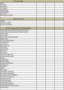
(1) list all components and verify you have ALL of them currently available including bolts, sealants and gaskets and assembly lube
viewtopic.php?f=51&t=7697&p=26187#p26187
head assembly,
valve cover & bolts
rockers,
rocker studs
stud girdle,
guide plates
valves,
springs,
retainers
keepers,
shims,
head bolts
etc.
block ,
viewtopic.php?f=51&t=7697&p=26187#p26187
with all machine work and clearance work and honing done and well cleaned
main caps and mount studs & nuts
freeze plugs
oil gallery plugs
timing cover and bolts
shrapnel screens
magnets
oil filter mount adapter and bolts
j&b weld epoxy
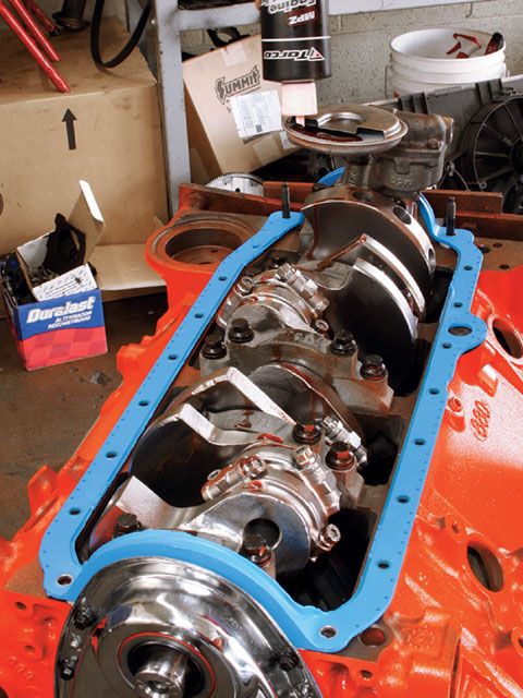
rotating assembly,
crank
connecting rods,
pistons,
pins,
snap rings or true locs
rings
damper,
flywheel/flex-plate
and mounting bolts,
bearings
lube system ,
oil pump,
oil pan,
oil pump mount stud,
oil pump pick-up,
windage screen,
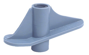
crank scraper
cam assembly,
lifters,
push rods,
timing chain
and timing gears,
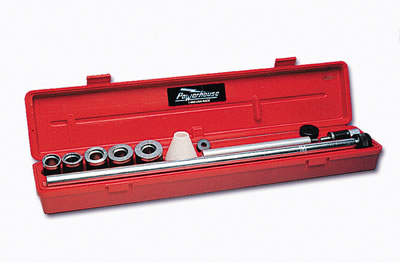
cam bearings
offset bushings
cam button
retaining lock plate
intake assembly, linkage, carb , or MPFI
sensors...as required
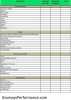
(2)verify you have all the tools required
sturdy engine stand (grade 8 mount bolts/washers)
large engine bag for storage and moisture control
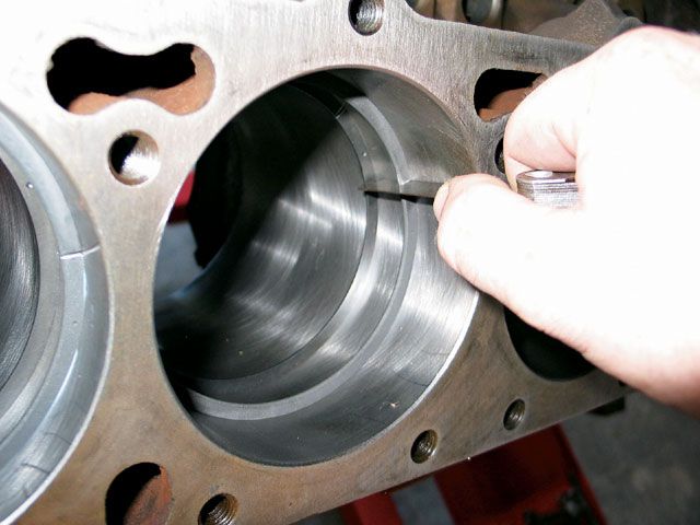
feeler gauges
snap gauges
ring compressor
true loc tool or snap ring pliers
majic marker
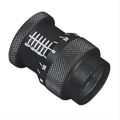
push rod length checker
torque wrench
crank socket
ring grinder
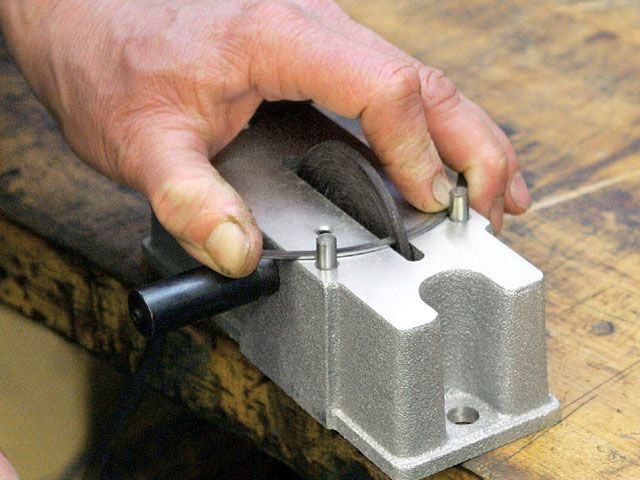
hone stone
mics
calipers
rubber mallet
rod bolt guides
damper puller/installer
assembly lube
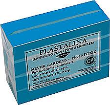
model clay
wd40
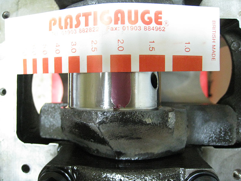
plasti gauge
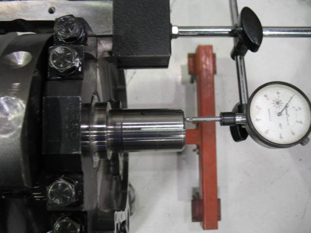
dial indicator and stand
dial indicator deck bridge
cam degree wheel and pointer
lifter/mic tool
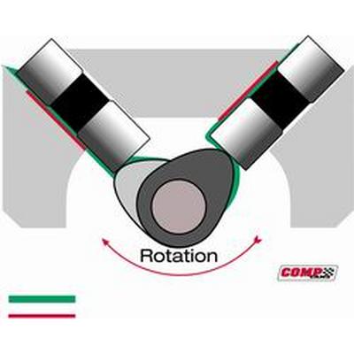
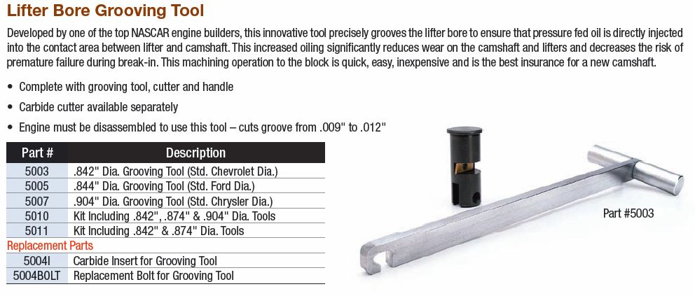
lifter bore groove tool
small jewelers files
drill and bit assortment
valve spring mic
TAPS
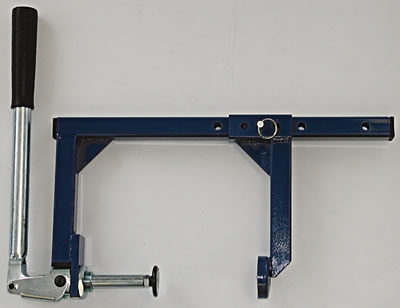
valve spring compressor


related info
http://www.popularhotrodding.com/engine ... index.html
viewtopic.php?f=51&t=7697&p=26187#p26187
head assembly,
valve cover & bolts
rockers,
rocker studs
stud girdle,
guide plates
valves,
springs,
retainers
keepers,
shims,
head bolts
etc.
block ,
viewtopic.php?f=51&t=7697&p=26187#p26187
with all machine work and clearance work and honing done and well cleaned
main caps and mount studs & nuts
freeze plugs
oil gallery plugs
timing cover and bolts
shrapnel screens
magnets
oil filter mount adapter and bolts
j&b weld epoxy
rotating assembly,
crank
connecting rods,
pistons,
pins,
snap rings or true locs
rings
damper,
flywheel/flex-plate
and mounting bolts,
bearings
lube system ,
oil pump,
oil pan,
oil pump mount stud,
oil pump pick-up,
windage screen,
crank scraper
cam assembly,
lifters,
push rods,
timing chain
and timing gears,
cam bearings
offset bushings
cam button
retaining lock plate
intake assembly, linkage, carb , or MPFI
sensors...as required
(2)verify you have all the tools required
sturdy engine stand (grade 8 mount bolts/washers)
large engine bag for storage and moisture control
feeler gauges
snap gauges
ring compressor
true loc tool or snap ring pliers
majic marker
push rod length checker
torque wrench
crank socket
ring grinder
hone stone
mics
calipers
rubber mallet
rod bolt guides
damper puller/installer
assembly lube
model clay
wd40
plasti gauge
dial indicator and stand
dial indicator deck bridge
cam degree wheel and pointer
lifter/mic tool
lifter bore groove tool
small jewelers files
drill and bit assortment
valve spring mic
TAPS
valve spring compressor
related info
http://www.popularhotrodding.com/engine ... index.html
Last edited by a moderator:
")