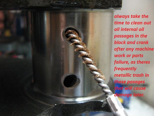
AS USUAL THERES A GREAT DEAL OF INFO IN THE LINKS AND SUB LINKS
http://underthehood.mahleclevite.com/?p=706
http://stealth316.com/misc/clevite-77-r ... arings.pdf
http://www.bobistheoilguy.com/bearingwe ... alysis.htm
viewtopic.php?f=44&t=10923
http://www.nb-cofrisa.com/docs/web_fallos_ing.PDF
http://www.precisionenginetech.com/tech ... ch-part-1/
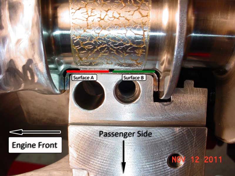
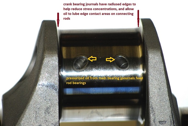
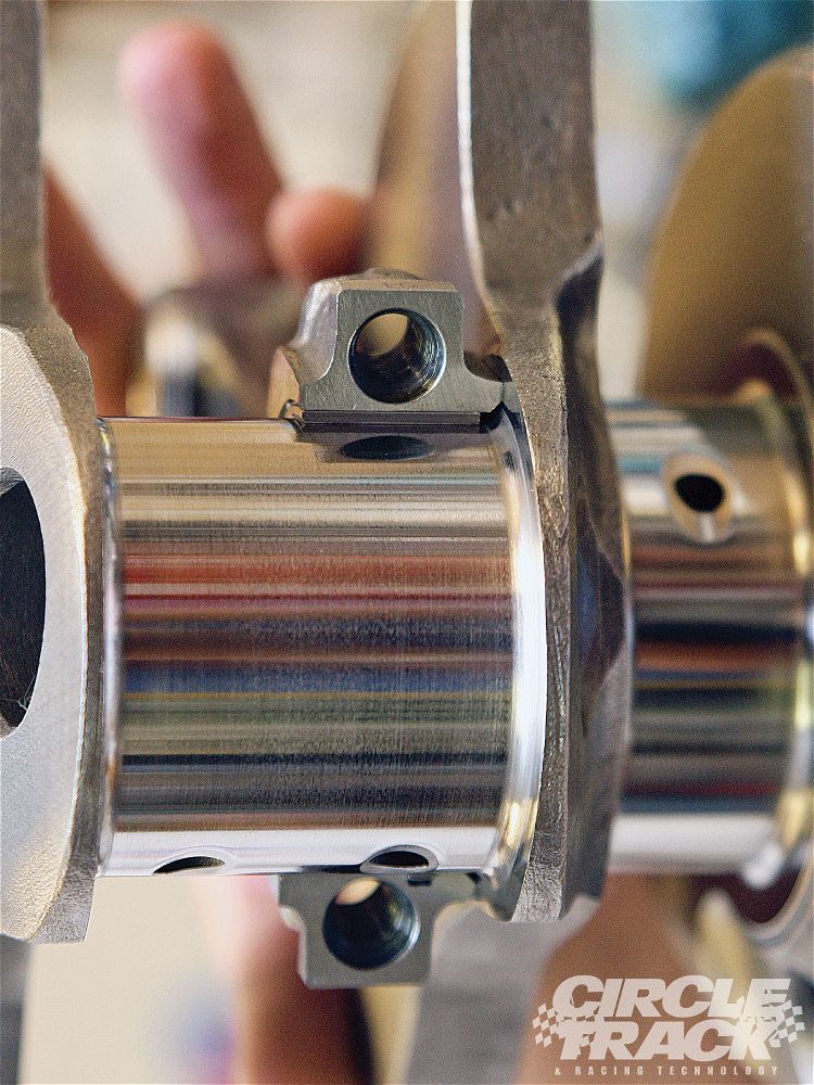
Crush
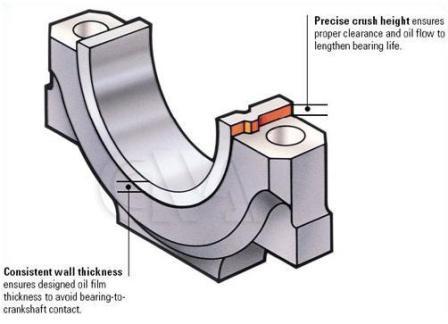
The term "crush" refers to the outward force created by the portion of the bearing which extends above the housing bore when the bearing halves are set into place. This "extra" material holds the outside diameter of the bearings firmly against the housing bore when the assembly is torqued to specification. By increasing the surface contact between the bearing and it's bore, crush minimizes bearing movement, helps to compensate for bore distortion and aids in heat transfer. Federal-Mogul's performance bearings have additional crush built into the design for enhanced heat transfer and bearing retention.
Eccentricity
"Eccentricity" refers to the variation in the inside diameter of a bearing assembly when it is measured at different points around its bore. A properly designed engine bearing is not truly "round" when it is installed in the connecting rod or engine block. Under operating loads, a rod or main housing bore will distort, pulling inward at the parting line between the upper and lower halves. To keep the bearing from contacting the crankshaft in these areas, our designs include additional clearance at each parting end of the bearing. As engine loads increase, so does the amount of distortion, thus race bearings require greater eccentricity than do passenger car bearings.
Clearance
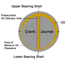
Vertical bearing clearance is best measured by assembling the bearing into its bore, measuring the inside diameter with a dial bore gauge and subtracting the actual crankshaft journal diameter. Clearance specifications shown in this catalog are the arithmetic ranges possible with parts that meet factory specifications, not clearance recommendations. Always use the engine manufacturer's clearance specifications. Clearance should be measured vertically – 90 degrees from the housing parting line. The eccentricity designed into bearings will cause clearance measurements to vary at different points around the bearing's inside bore.
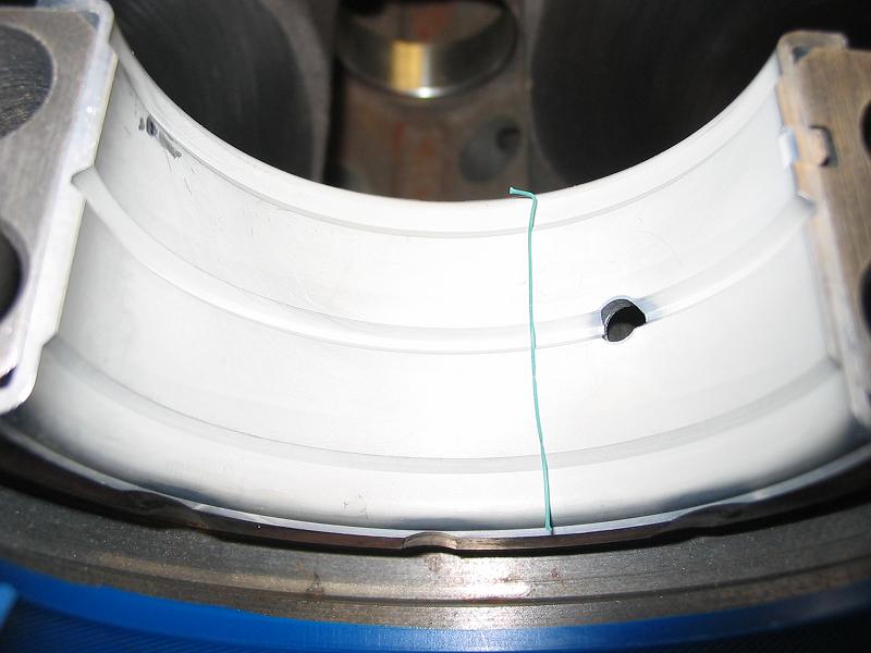
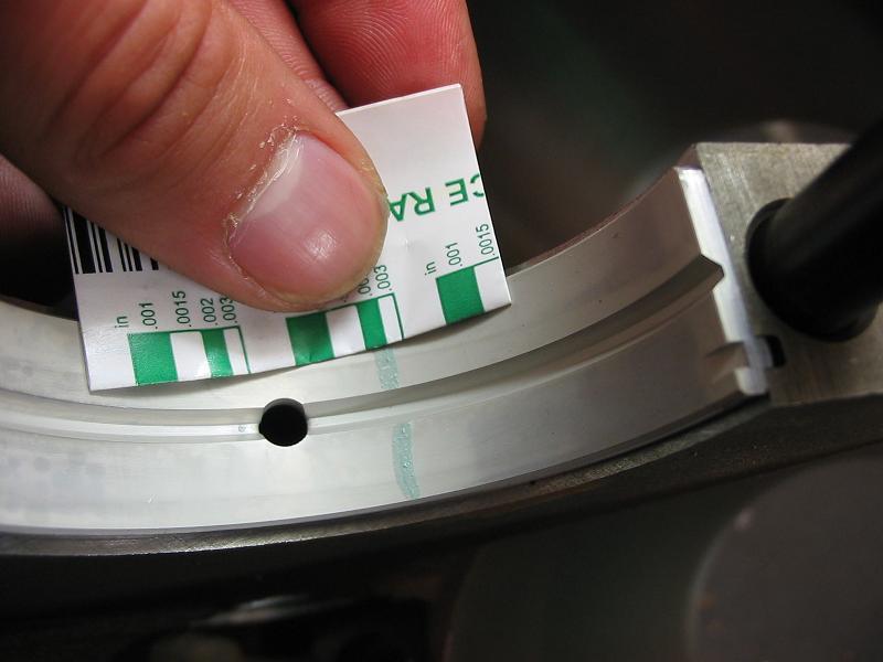
Plastigage can be used as a quick way to check clearance. To use plastigage correctly, first assemble the upper bearing shell into the housing, then install the crankshaft. Lay a strip of plastigage lengthwise across the center of the bearing journal. Install the lower bearing shell and cap and tighten the fasteners to the specified torque. Loosen the bolts and remove the bearing cap and lower shell, being careful not to rotate the crankshaft. Compare the thickness of the now compressed plastigage strip to the chart on its package to determine the bearing clearance. Carefully remove all traces of plastigage from both the crankshaft journal and the bearing before final assembly.
High performance applications may require different bearing clearances than unmodified engines. Many engine builders target a clearance range between .0022" and .0027". Clearances greater than .003" are not normally recommended. Some engine builders like higher oil pressures than a standard oil pump can provide, particularly at lower engine speeds. Large bearing clearances will lower oil pressure, and may require a high volume oil pump. An engine should maintain a minimum oil pressure of 10 lbs. per 1000 RPM.
Plastigage
Plastigage is a quick and easy device for checking bearing clearances. Available in four ranges to cover most applications. Twelve strips per package with a measurement gauge printed on each wrapper.
SPG-1 (green) .001 – .003 (.025MM – .075MM) range
SPR-1 (red) .002 – .006 (.050MM – .15MM) range
SPB-1 (blue) .004 – .009 (.10MM – .23MM) range
SPY-1 (yellow) .009 – .020 (.23MM – .50MM) range
READ LINKS AND SUB LINKS
viewtopic.php?f=53&t=2726&p=7077&hilit=plastigauge#p7077
viewtopic.php?f=44&t=5531&p=39484&hilit=plastigauge#p39484
viewtopic.php?f=53&t=9955&p=38385&hilit=plastigauge#p38385
to Metals
to Engine bearings
Dr. Dmitri Kopeliovich

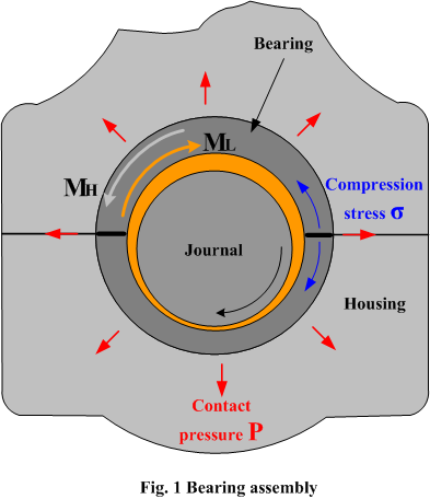
The contact pressure also produces a friction between the bearing back and the housing surface which contradicts the friction generated by the journal rotating in the bearing (ML). The torque of the friction force formed between the bearing back and the housing MH prevents the bearing from shifting in the housing.
High performance bearings working at heavy loads, high rotation speeds and increased temperatures should be installed with a higher contact pressure. This provides better heat transfer and secures the bearing more tightly in the housing.
to top
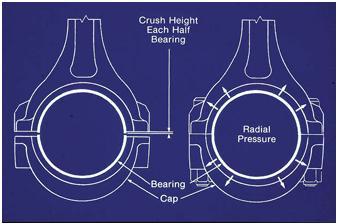
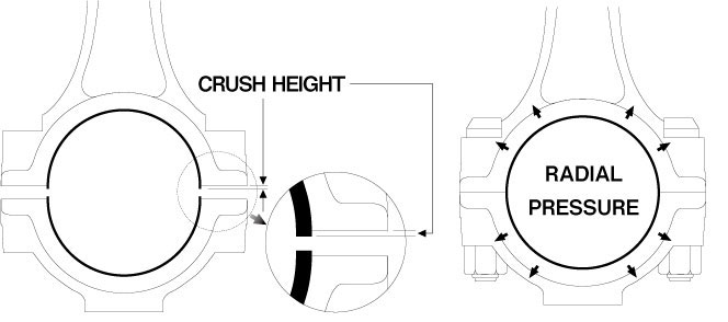
crush height.
Crush height is the difference between the outside circumferential length of a half bearing (one half shell) and half of the housing circumference [1] measured at a certain press load.
Fig.2 illustrates a device for measuring crush height.

The tested bearing is installed in the gauge block and pressed with a predetermined force F. The force is proportional to the cross-section area of the bearing wall.
The optimal value for crush height is dependent on the bearing diameter, housing material (modulus of elasticity and thermal expansion), housing dimensions and stricture (rigidity), and temperature.

However the calculation results did not take into account a temperature increase. The crush height is measured at a normal ambient temperature, but the bearing together with its housing heat up during bearing operation. If bearing and housing are made of materials with different coefficients of thermal expansion, the effective crush height (interference) will be different from that measured at room temperature.
The most significant difference between the thermal expansions of the bearing and housing is realized when the housing is made of aluminum.
Fig.4 shows the effect of temperature on the contact pressure of the bearing (CR 807XPN) in an aluminum housing.

The graph shows that the required level of contact pressure in the heated aluminum housing may be achieved only if the crush height is not less than 0.009”.
Another factor affecting contact pressure is the rigidity of the bearing housing, determined by the housing dimensions and shape. Fig.5 presents the calculation results of the effect of the housing diameter on the contact pressure of the bearing in housings made of three different materials. The calculations are made for crush height ch = 0.005”.
The graph shows that the steel housing provides the required contact pressure even at a diameter as low as 1.25 of the bearing diameter. The contact pressure 1500 psi in a titanium housing is achieved at its diameter greater than 1.4 of the bearing diameter. The diameter of an aluminum housing should be at least 1.75 of the bearing diameter.

A tighter contact between bearing and housing may also be obtained by an increase of the thickness of the bearing steel back.
The effect of bearing thickness on contact pressure is shown in Fig.6.
The required minimum value of 1500 psi pressure in a steel housing is achieved with a bearing whose steel back is thicker than 0.047”, whereas the bearing back thickness in an aluminum housing should be at least 0.077” and 0.057” in titanium housing.

Thus, the design of crush height in a high performance bearing should take into account not only severe operating conditions (heavy load and high rotation speed), but also the housing parameters (material, shape, dimensions), bearing dimensions and the ambient working temperature.
However, there are limits to the minimum amount of crush height as well as the maximum amount of crush height. When a bearing with excessive crush height is installed and tightened in the housing, the material in the region of the parting line exerts an inward displacement which reduces the gap between the journal and the bearing surfaces in this area. The change of bearing profile at the parting line region results in the formation of peak oil film pressure, which may cause fatigue of the bearing material [3].
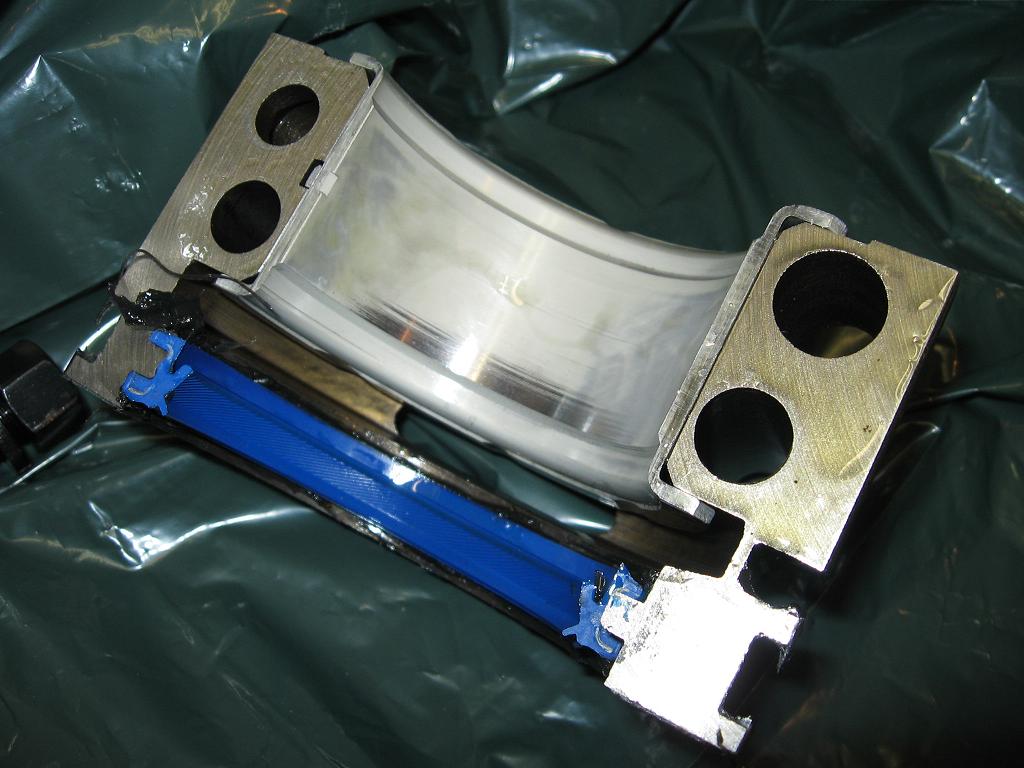
A bearing affected with fatigue cracks in the area of crush relief is shown in Fig.7.
The compression stress in the bearing was 72,300 psi which is greater than the maximum value of 65,000 psi.

to top
regime of hydrodynamic lubrication [4]. The value of hydrodynamic friction torque developed using King high performance bearing CR 807XPN was calculated assuming the use of 15W50 oil, and a wide range of rotation speeds, oil clearances and eccentricity.
The calculations were performed using software developed by King Engine Bearings. This software is capable of calculating loads, friction forces, minimum oil film thickness, oil temperature rise, energy loss, oil flow rate and other thermodynamic, dynamic and hydrodynamic parameters for each bearing of an engine at any angular position of the crankshaft.
The maximum value of hydrodynamic friction torque ML resulted in a value of approximately 2 ft*lb.
The torque MH required to spin the bearing in the housing is about 100 ft*lb (corresponds to the contact pressure of 2630 psi).
Thus the safety factor is about 50 - sufficiently large enough to prevent spinning. Even if lubrication turned to mixed regime, the journal friction torque will be much lower than the torque keeping the bearing from spinning in the housing.
Last edited by a moderator: