Cam Break-in Procedure
OK step one you NEVER start an engine with a new cam until you've verified ALL clearances and valve train geometry are correct!
verify the oil and coolant levels are correct and rotate the engine by hand several times to verify nothing binds!
have a running garden hose handy for use in cooling the radiator and having a fire extinguisher handy is potentially a huge help if things go badly!
and you have pre-lubed the engine while slowly manually rotating the crank until all push rods show oil flow,at the rockers and the gauge shows a minimum of 10 psi have you not?
Id watch the coolant temperature and oil pressure constantly, and have checked fuel pressure , carburetor float levels, or fuel pressure in the injector fuel rails and injector resistance.
honestly this takes a good deal longer to post about and discuss that to correct and check, so what ever method you might select ,Adjusting the valves on any new engine as it is a rather simple procedure, that youll need to go thru on almost any new engine instal and you can use the E-O, I-C method,or if your experienced the adjustments easily done at idle speed, your choice, either works just fine if you know what your doing.
Obviously having a timing light and a multi meter handy and having previously verified the timing marks on the damper and timing tab reflect true TDC, is mandatory before you begin the start up process , knowing how to adjust the valves helps a great deal, and you certainly should have long ago verified the cam timing by degreeing in the cam and you dis check the piston to valve clearances, valve train geometry and valve train clearances and rotating assembly clearances .most guys I know , that are breaking in the rings and bearings and valve train on a newly rebuilt engine, simply stick a garden hose into the radiator and let it constantly overflow onto the driveway , or they fill the radiator and seal it then place a garden hose so it runs water over the radiator outer surface,while the engine, and cam is being broken in, as its a sure way to keep the coolant temps fairly low. so no.there's no reason you can't fill the radiator with water, break in the engine then replace the coolant!, so if you do have a coolant leak your not leaking anti-freeze all over the place, until you get the engine tested and broken in, BTW (be sure all the gauges and sensors are correctly hooked up and working) have a timing light , distributor wrench,and fire extinguisher handy and I usually try to have a dripping wet beach towel handy as its great for quickly smothering carb fires, without the mess a fire extinguisher makes, if you get unlucky and be sure you double check the oil and trans fluid and be sure to fill and bleed the brakes and check power steering fluids also
its the stupid simple stuff that most guys forget!
don,t forget to double and triple check all the fluids levels, is there at least 6 gallons of fresh gas in the tank?,did you put in and check,the fuel filter and check for leaks , verify the fuel pressure regulator works, gauges work?,battery has a full charge? ,engine oil, level, on the dip stick, coolant,level in radiator, brake fluid,bleed brakes, check, transmission fluid , and make sure converters full, verify the tires air pressures good,brake lights work, brakes work,steering works, battery is not loose , have you verified full flawless function of the throttle linkage,and transmission shifter linkage, that fan belts are aligned and tight, lug nuts are tight, u-joint bolts are fastened, radiator hose clamps are tight?, trans coolant lines are tight? got your license and registration, insurance, a cell phone? and some one too tow you home if that's required? ?etc.
have a running garden hose very close by to cool the radiator and a soaking wet beach towel and fire extinguisher in case of a fire related mistake,you'll want a timing light, multi meter and infra-red temp-gun for trouble shooting
its a hydraulic roller cam, and lifter valve train, so your not concerned with the cam lobes, and roller lifters breaking in ,too near the extent a flat tappet cam might be, but obviously the rockers need to be correctly adjusted ,and the rings need time to seat and the transmission needs to wear in, a bit so driving it under load running it up thru the rpm's ranges changing gears will help, and frequent rechecks of fluid levels and temps and an eye on the gauges is always advisable
you might want to read thru this
preventing cam & lifter break-in failures
viewtopic.php?f=52&t=181&p=6764&hilit=erson+break+in#p6764
http://www.gmpartsdirect.com/results.cfm?partnumber=EOS
http://www.gmpartsdirect.com/results.cf ... number=EOS
viewtopic.php?f=62&t=1515
viewtopic.php?f=52&t=2166&p=5840#p5840
viewtopic.php?f=44&t=366&p=448#p448
viewtopic.php?f=52&t=130&p=160&hilit=erson+break#p160
HERES A COUPLE REAL GOOD ENGINE ASSEMBLY THREADS
viewtopic.php?f=69&t=3814
viewtopic.php?f=50&t=428
viewtopic.php?f=52&t=10182&p=40244#p40244
viewtopic.php?f=44&t=38
viewtopic.php?f=52&t=399
viewtopic.php?f=52&t=181
viewtopic.php?f=53&t=247
I know some of you gentlemen would rather dig your own eyes out of your face with a rusty fork than read links, sub-links and posted info, but amazingly there useful info , in them, like tools that let you detect cam wear early, when to swap filters
what lubes to use,how to adjust and clearance valve trains, use of magnets to trap metallic crud and limit damage, which filters to use, etc.
the total amount of assembly lube you put on the cam and rotating assembly rarely can exceed 4 OZ and that EASILY fits into an oil filter, so if your getting more crud than the first oil filter traps in the first 30 minutes during the engine brake-in process, logic says its COMING from someplace and a quick look at the filter internals with the tool linked above and the magnets you should have installed should give you a good idea as to the source
http://store.summitracing.com/partdetail.asp?autofilter=1&part=SUM-900510&N=700+115&autoview=sku
http://forum.grumpysperformance.com/viewtopic.php?f=44&t=799&p=1161#p1161
http://forum.grumpysperformance.com/viewtopic.php?f=32&t=939&p=1582&hilit=+filter+tool#p1582
http://forum.grumpysperformance.com/viewtopic.php?f=52&t=282
http://www.ls1howto.com/index.php?article=23
viewtopic.php?f=54&t=120&p=867&hilit=+magnets#p867
http://www.pbm-erson.com/uploads/cat%5B ... CEDURE.pdf
http://www.corvetteactioncenter.com/tech/oil/index.html
OPTIONS
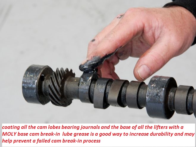
it should be rather obvious that theres options, cam failures are usually the result of incorrect CLEARANCES or too much SPRING PRESSURE or LACK of ADEQUATE LUBRICATION,USE DECENT MOLY CAM LUBE, and decent quality oil, adding MAGNETS to trap metallic CRUD HELPS, be sure to change your oil filter and oil after the first 3-4 hours or 100 miles as theres bound to be crud and assembly lube trapped in the oil and filter
Ive almost always used about 90% of a good brand of synthetic oil and 10% marvel mystery oil in my engines for MANY years, I generally change both the oil and oil filters in the 3500-5000 mile range and they always come apart during inspections looking like new, what many guys don,t realize is that M.M.O. is just a high quality light oil with a high percentage of solvents and detergents, its not an oil additive in the common sense of the word, just an oil that tends to dissolve crud effectively
... with hydraulic lifters the push rod seat needs to have sufficient slack or clearance to allow oil to fill the area under the push rod seat that's supposed to be supported on a cushion of oil
if you adjusted the valve train with out that oil holding the push rod seat up, the lifter will push very little oil up the push rods to the rockers and will sometimes result in excessive wear like you describe.
THAT'S why IVE always preferred the hydraulic cams be adjusted at idle by backing off the rocker nuts until the rocker clicks and slowly tightening the rocker nut just to the point the clicking stops then adding a 1/4 turn of preload, this allows the lifter to pump up.
viewtopic.php?f=54&t=985
viewtopic.php?f=52&t=196
viewtopic.php?f=52&t=121
viewtopic.php?f=32&t=939&p=1582&hilit=+filter+tool#p1582
you might want to read thru this info and all the sub links first
viewtopic.php?f=52&t=965
viewtopic.php?f=52&t=90
viewtopic.php?f=52&t=282&p=2022#p2022
viewtopic.php?f=54&t=1057&p=2009#p2009
• Have a high quality service manual available, such as the factory service manual, or the vehicle specific manuals published by Chiltons, Motors, or Haynes. You will need these for the basic information regarding engine disassemble and reassemble along with the torque settings for the various fasteners.
• Read and understand the manual completely, along with these instructions before you begin working. We highly recommend you also have the assistance of a knowledgeable friend to assist you, especially during the initial fire-up and break-in period.
In addition to the normal installation procedure, installing a performance camshaft requires you to check for several extra items to insure long life and optimum performance.
• New Lifters Are A Must- There is no such thing as a good used lifter! Any flat faced lifter establishes a wear pattern almost immediately with the cam lobe it is riding on and cannot be used on any other cam lobe, let alone a different cam. Should you have a need to disassemble the engine, make sure you keep the lifters in order so they go back on to the exact same lobes.
• Valve Spring Pressure and Travel- We highly recommend purchasing the matching valve springs recommended in our catalog. This insures you will have the proper pressures, both closed and open, and sufficient travel to get the maximum rpm, performance and life from your new cam.
• Piston to Valve Clearance- While many performance cams will work just fine with stock pistons, there are many factors that effect your engine and the clearance available. Things such as factory tolerances, normal machine work such as head and block surfacing, aftermarket components such as cylinder heads, higher ratio rocker arms, etc. all effect your engines ability to handle a performance camshaft.
• Valve Train Interference- In addition to valve spring travel and piston-to-valve clearance, a commonly overlooked area is that of retainer to seal clearance. The other common area of interference is rocker arm to stud clearance along with rocker arm travel. The best way to check these is by physically opening both a intake and an exhaust valve on each cylinder head to the gross lift of the cam plus and additional .030". It is easiest to do this by pressing down on the rocker arm with one of the many tools available. Do not simply rotate the engine to the maximum lift point for a given valve. This does not work when engines are hydraulic lifter equipped, or even allow any margin of safety when you are using a mechanical lifter cam.
• Valve Adjustment- The easiest way to insure proper adjustment is to adjust the rocker arms as you install them, one cylinder at a time. Adjust the intake valve as the exhaust valve is just starting to open and adjust the exhaust valve when the intake valve is almost closed. It is simplest to do this with the intake manifold off and watching the lifter’s movement.
• Hydraulic Lifter Valve Adjustment- All engines, regardless of manufacture, require correct valve adjustment. Some engines, such as Chevrolet V-8’s, are equipped with stud mounted rocker arms can easily be adjusted to compensate for changes incurred during engine assembly. Never just torque the rocker arm into place and assume that the lifter pre-load will automatically be correct. Various engine manufacturers use multiple length push rods, shims, and spacers to compensate for changes in pre-load. Hydraulic lifters cannot compensate for all changes. Ideal lifter pre-load is .020" to .080". Do not attempt to fill the lifters full of oil prior to installation. They will fill automatically once started and manually filling them makes adjusting the pre-load a difficult task.
• Mechanical Lifter Valve Adjustment- Adjusting mechanical lifters should be done the same way as outlined above, one valve at a time. For an initial setting, we recommend .003" to .005" than listed on the cam’s specification card. Once broken in and with the engine fully warmed up, re set the rocker arms to the cam’s specification sheet.
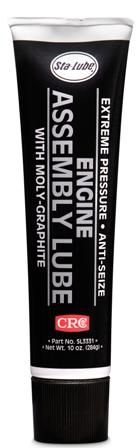
• Installation Lubricants- All flat faced (non-roller) camshafts require the use of high pressure lubricant supplied with your Erson cam on the bottom of the lifters, the lobes of the cam and on the distributor drive gear. Do not use this lube on the tips of the pushrods, the sides of the lifters or on the rocker arms. Use a quality oil when installing roller tappets.
BEFORE YOU TURN THE KEY
• Fill All of the Engine’s Fluids- Using a minimum of a SAE API SD, SE or better fresh clean mineral based oil, fill the engine to the proper level. Do not use synthetic oil during break-in. Fill the coolant system and follow the instructions on purging air from the system. With carburetor equipped engines, fill the carburetor to insure fuel is available immediately. Make sure that the ignition timing is properly set to insure immediate starting, without excess cranking of the engine.
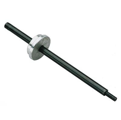
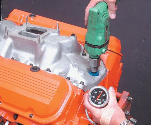
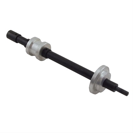
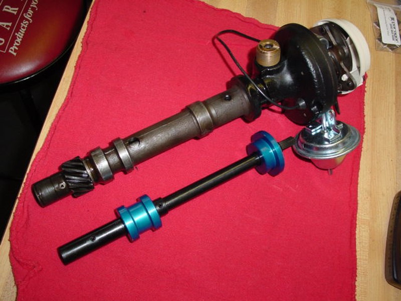
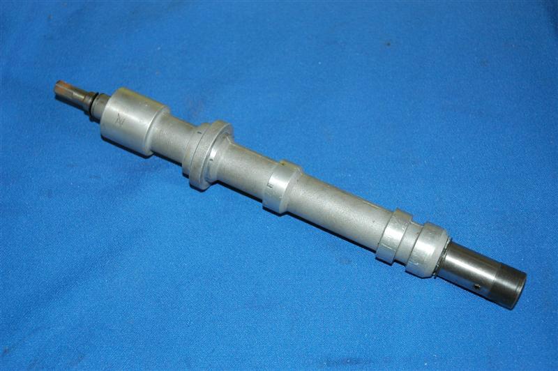
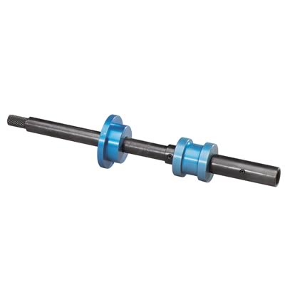
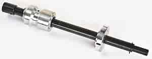
• Pre-Lube the Engine- Using a oil pump priming tool such as those available from Mallory, spin the engine’s oil pump until you see pressure on the gauge or have oil at the rocker arms. Do not attempt to prime the engine using the starter motor!
• Proper Ventilation- Make sure that you do not start the engine without good airflow. That means have the overhead garage door open and the exhaust vented to the outside. If you have any doubts about sufficient airflow to the engine, push the car out of the garage to make sure the radiator can draw in plenty of air. Having a fan to blow fresh air through the garage is a plus.
• Exhaust System- If at all possible, start the car with a muffled exhaust system hooked up and operational. It makes it much easier to hear what is going on.
• Resist the Urge- Take a minute before you try to start the engine for the first time and double check that you are ready to go. Don’t take any short cuts or leave parts such as fan shrouds, air cleaner, wire looms, etc. off. Clean up the are around and especially under your vehicle. Pick up your tools and wipe up the floor so you can easily spot even a minor leak.
• Be Prepared- Have extra coolant or a hose handy, clean rags, tools for tightening clamps, connections, etc. just in case. They need to be in place to make sure you have an uneventful break-in of the camshaft.
WHEN THE ENGINE STARTS
• Have a Helper- Now is the time for a helper. They can check the coolant level, check for oil and fluid leaks, and proper operation of under hood accessories. Air pockets in the coolant system are common so make sure the recovery bottle is checked and filled as necessary. You cannot count on the temperature gauge. Temperature gauges are only accurate if the sensor is submerged in coolant and will not give an accurate reading if in an air pocket.
• Do Not Idle the Engine- As soon as the engine starts, raise the rpm to 2,000 rpm. You should also constantly vary the RPM between 2,000 and 3,000 RPM for the first 20 minutes. This is the only way to insure proper lubrication during this critical period since the camshaft to lifter contact area relies almost exclusively on oil splash from the crank and connecting rods. Make sure that you run the engine for a full 20 minutes using this procedure. It will seem like forever, but it is one of the most important steps to insure long, dependable performance.
Ive always smiled when I saw that same instruction, thinking, now how in hell are you going to set the timing at idle when your not allowed to let the engine idle during the cam break-in process, years ago thinking the same question,the answers simple but it takes experience before you realize the answer, you simply set the timing with a TIMING TAPE on the damper at about 32-36 degrees at 3000rpm, and watch the temperature on the exhaust with an INFRARED temp gun,as a guide in almost all or at least most cases, if the exhaust gets cherry red quickly its usually an indicator your ignition timing is retarded or the fuel/air mix is lean,that will be very close to correct when you drop the rpms to 1000 once the cams broken in, after 30 minutes, obviously you need to find TDC during the cam installation and degreeing in process an install a timing tape or use a pre-marked damper, so you can accurately set the timing at 3000rpm
Once Break-in is Complete- Drain and replace the engine oil and filter with new, fresh oil and a new filter. Recheck for any fluid leaks and check all fluid levels. If you installed a mechanical lifter style camshaft, flat faced or roller style, the valve adjustment should be rechecked at this time with the engine fully warmed up. Hydraulic lifter equipped engines should not require any readjustment.
Proper maintenance is important for any vehicle. Frequent oil changes, with a new filter is one of the easiest ways to insure your vehicle will deliver the performance you want for many long happy miles.
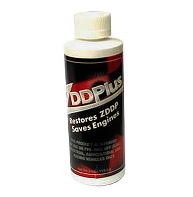
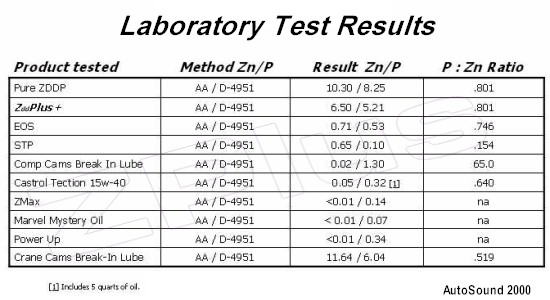
ID ADD, USE a GOOD MOLY BASE ASSEMBLY LUBE AND A HIGH ZINC CONTENT OIL AND SOME G.M. E.O.S. TO THE OIL
MARVEL MYSTERY OIL is a good high detergent oil designed to aid valve train and rings ETC. cleaning, I almost always add about 10% marvel mystery oil to my engines, but if your running flat tappet lifters Id point out that many current oils are designed for roller lifter engines so Id select an oil that's designed for the older design with the higher zinc content, and adding a can of E.O.S. to the oil and moly assembly lube on the lifters and cam, sure won,t hurt on that first break in, if your breaking in the engine in your driveway, have a running hose and a fan handy, water running thru the radiators cooling fins and a fan blowing air helps prevent over heating, have a timing light and USE IT, check your fluid levels and watch your gauges
GM’S RECOMMENDED CRATE ENGINE START-UP PROCEDURE
Print this page out and check off boxes below (in the printed copy) when each step is completed.
Step Box
1) Safety first! If the car is on the ground, be sure the emergency brake is set, the wheels are chocked, and the transmission cannot fall into gear. Next verify that all hoses are tight and that both the radiator and radiator over flow jar/tank are full and have been filled with the proper anti-freeze and water mix.
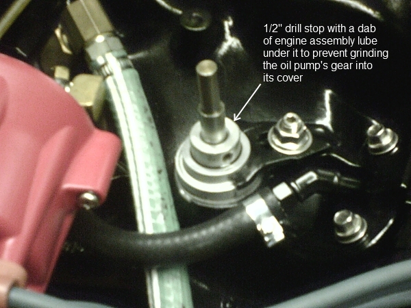
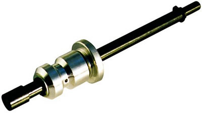
2) Before starting your engine for the first time, add one pint of engine oil supplement ( EOS¹) to the crankcase oil and then check the oil level. Once this has been done, prime the oil system with an oil pump primer tool. Make sure number 1 cylinder is on TDC compression stroke, and install the distributor.
3) Adjust the distributor timing roughly by hand for a quick start up and smoothest idle possible.
4) When the engine first starts, verify that the engine rpm is at a safe level and that the timing is set near or at 30° before top dead center (BTDC). Run the engine speed between 1,500 and 2,500 RPM’s, varying the engine speed up and down with-in this range, to prevent overheating of the exhaust valves and the exhaust system. This should be done with no-load on the engine and for the first 30 minutes of operation.
5) After the first 30 minutes of the engine running, set the ignition timing according to the timing specifications. Now would be a good time to check thoroughly for leaks.
6) Adjust the carburetor settings, if necessary.
7) Drive the vehicle with varying speeds and loads on the engine for the first 30 miles. Be sure not to use a lot of throttle or high RPM.
8) Run five or six medium-throttle accelerations to about 3,800 RPM (55 to 60 MPH), then letting off in gear and coasting back down to 20 MPH.
9) Run a couple hard-throttle accelerations up to about 3,800 RPM (55 to 60 MPH), then letting off in gear and coasting back down to 20 MPH.
10) Change the oil and filter with recommended oil (10w30SG in most cases) and filter.
11) Drive the next 500 miles normally, without high RPM’s (below 3,800 RPM), hard use, or extended periods of high loading.
12) Change oil and filter again.
13) Your engine is now ready for many happy cruising miles!
Note¹: EOS P/N 1052367 can be used any time during the life of the engine.
Technical Note: This procedure has been corrected and improved from the original GMPP procedure by GILBERT CHEVROLET.
sitting with no air other than the fan moving air thru the radiator is bound to run a bit hotter than on the road, anything under 220F is normal /expected under those conditions.
I run a water hose thru the radiators cooling fins when testing under those conditions., on the street it should run fairly consistently in the 180F-190F range with a 180F T-stat.
in many cases an ADDITIONAL TAURUS electric fan from a salvage yard can be installed on the other side of the radiator to run off a dash switch or sensor that will provide additional cooling when needed.(price varies but its usually very reasonable from salvage yards)
http://forums.hybridz.org/attachment.ph ... 1218835261
viewtopic.php?f=52&t=196
190F-210F is ABOUT NORMAL,for driving temps, and nothing to worry about, adding a separately mounted TRANSMISSION COOLER if you have an auto trans is usually worth a 10-15 degree drop in the coolant temp,MINIMUM, if the current trans fluids cooled in the lower radiator, adding an 8 qt baffled oil pan is usually good for an additional 7F-10F degrees reduction in oil temp alone
A great deal of the heat is transferred to the oil and trans fluids long before the radiator and coolant sees it,routing the hot trans fluid to an aux cooler and adding a high capacity oil pan significantly reduces the heat the radiator needs to transfer from the coolant to the air flow thru it.
http://store.summitracing.com/partdetai ... toview=sku
its been my experience that many cam failures are related to clearance issues or lack of correct lubrication far more than the use of the less than ideal spring load rates.
you might be amazed at the number of guys I see who install valve springs, even shim them to the correct height but never check the retainer to guide clearance,valve seals or valve train geometry, or bother to verify the oil flow thru the valve train, on all 16 rockers
and adding a few of the correct magnets traps almost all the metallic crud from worn lifters and lobes BEFORE it gets into the oil pump
viewtopic.php?f=52&t=282
viewtopic.php?f=52&t=181
OK step one you NEVER start an engine with a new cam until you've verified ALL clearances and valve train geometry are correct!
verify the oil and coolant levels are correct and rotate the engine by hand several times to verify nothing binds!
have a running garden hose handy for use in cooling the radiator and having a fire extinguisher handy is potentially a huge help if things go badly!
and you have pre-lubed the engine while slowly manually rotating the crank until all push rods show oil flow,at the rockers and the gauge shows a minimum of 10 psi have you not?
Id watch the coolant temperature and oil pressure constantly, and have checked fuel pressure , carburetor float levels, or fuel pressure in the injector fuel rails and injector resistance.
honestly this takes a good deal longer to post about and discuss that to correct and check, so what ever method you might select ,Adjusting the valves on any new engine as it is a rather simple procedure, that youll need to go thru on almost any new engine instal and you can use the E-O, I-C method,or if your experienced the adjustments easily done at idle speed, your choice, either works just fine if you know what your doing.
Obviously having a timing light and a multi meter handy and having previously verified the timing marks on the damper and timing tab reflect true TDC, is mandatory before you begin the start up process , knowing how to adjust the valves helps a great deal, and you certainly should have long ago verified the cam timing by degreeing in the cam and you dis check the piston to valve clearances, valve train geometry and valve train clearances and rotating assembly clearances .most guys I know , that are breaking in the rings and bearings and valve train on a newly rebuilt engine, simply stick a garden hose into the radiator and let it constantly overflow onto the driveway , or they fill the radiator and seal it then place a garden hose so it runs water over the radiator outer surface,while the engine, and cam is being broken in, as its a sure way to keep the coolant temps fairly low. so no.there's no reason you can't fill the radiator with water, break in the engine then replace the coolant!, so if you do have a coolant leak your not leaking anti-freeze all over the place, until you get the engine tested and broken in, BTW (be sure all the gauges and sensors are correctly hooked up and working) have a timing light , distributor wrench,and fire extinguisher handy and I usually try to have a dripping wet beach towel handy as its great for quickly smothering carb fires, without the mess a fire extinguisher makes, if you get unlucky and be sure you double check the oil and trans fluid and be sure to fill and bleed the brakes and check power steering fluids also
its the stupid simple stuff that most guys forget!
don,t forget to double and triple check all the fluids levels, is there at least 6 gallons of fresh gas in the tank?,did you put in and check,the fuel filter and check for leaks , verify the fuel pressure regulator works, gauges work?,battery has a full charge? ,engine oil, level, on the dip stick, coolant,level in radiator, brake fluid,bleed brakes, check, transmission fluid , and make sure converters full, verify the tires air pressures good,brake lights work, brakes work,steering works, battery is not loose , have you verified full flawless function of the throttle linkage,and transmission shifter linkage, that fan belts are aligned and tight, lug nuts are tight, u-joint bolts are fastened, radiator hose clamps are tight?, trans coolant lines are tight? got your license and registration, insurance, a cell phone? and some one too tow you home if that's required? ?etc.
have a running garden hose very close by to cool the radiator and a soaking wet beach towel and fire extinguisher in case of a fire related mistake,you'll want a timing light, multi meter and infra-red temp-gun for trouble shooting
its a hydraulic roller cam, and lifter valve train, so your not concerned with the cam lobes, and roller lifters breaking in ,too near the extent a flat tappet cam might be, but obviously the rockers need to be correctly adjusted ,and the rings need time to seat and the transmission needs to wear in, a bit so driving it under load running it up thru the rpm's ranges changing gears will help, and frequent rechecks of fluid levels and temps and an eye on the gauges is always advisable
you might want to read thru this
preventing cam & lifter break-in failures
viewtopic.php?f=52&t=181&p=6764&hilit=erson+break+in#p6764
http://www.gmpartsdirect.com/results.cfm?partnumber=EOS
http://www.gmpartsdirect.com/results.cf ... number=EOS
viewtopic.php?f=62&t=1515
viewtopic.php?f=52&t=2166&p=5840#p5840
viewtopic.php?f=44&t=366&p=448#p448
viewtopic.php?f=52&t=130&p=160&hilit=erson+break#p160
HERES A COUPLE REAL GOOD ENGINE ASSEMBLY THREADS
viewtopic.php?f=69&t=3814
viewtopic.php?f=50&t=428
viewtopic.php?f=52&t=10182&p=40244#p40244
viewtopic.php?f=44&t=38
viewtopic.php?f=52&t=399
viewtopic.php?f=52&t=181
viewtopic.php?f=53&t=247
I know some of you gentlemen would rather dig your own eyes out of your face with a rusty fork than read links, sub-links and posted info, but amazingly there useful info , in them, like tools that let you detect cam wear early, when to swap filters
what lubes to use,how to adjust and clearance valve trains, use of magnets to trap metallic crud and limit damage, which filters to use, etc.
the total amount of assembly lube you put on the cam and rotating assembly rarely can exceed 4 OZ and that EASILY fits into an oil filter, so if your getting more crud than the first oil filter traps in the first 30 minutes during the engine brake-in process, logic says its COMING from someplace and a quick look at the filter internals with the tool linked above and the magnets you should have installed should give you a good idea as to the source
http://store.summitracing.com/partdetail.asp?autofilter=1&part=SUM-900510&N=700+115&autoview=sku
http://forum.grumpysperformance.com/viewtopic.php?f=44&t=799&p=1161#p1161
http://forum.grumpysperformance.com/viewtopic.php?f=32&t=939&p=1582&hilit=+filter+tool#p1582
http://forum.grumpysperformance.com/viewtopic.php?f=52&t=282
http://www.ls1howto.com/index.php?article=23
viewtopic.php?f=54&t=120&p=867&hilit=+magnets#p867
http://www.pbm-erson.com/uploads/cat%5B ... CEDURE.pdf
http://www.corvetteactioncenter.com/tech/oil/index.html
OPTIONS
it should be rather obvious that theres options, cam failures are usually the result of incorrect CLEARANCES or too much SPRING PRESSURE or LACK of ADEQUATE LUBRICATION,USE DECENT MOLY CAM LUBE, and decent quality oil, adding MAGNETS to trap metallic CRUD HELPS, be sure to change your oil filter and oil after the first 3-4 hours or 100 miles as theres bound to be crud and assembly lube trapped in the oil and filter
Ive almost always used about 90% of a good brand of synthetic oil and 10% marvel mystery oil in my engines for MANY years, I generally change both the oil and oil filters in the 3500-5000 mile range and they always come apart during inspections looking like new, what many guys don,t realize is that M.M.O. is just a high quality light oil with a high percentage of solvents and detergents, its not an oil additive in the common sense of the word, just an oil that tends to dissolve crud effectively
... with hydraulic lifters the push rod seat needs to have sufficient slack or clearance to allow oil to fill the area under the push rod seat that's supposed to be supported on a cushion of oil
if you adjusted the valve train with out that oil holding the push rod seat up, the lifter will push very little oil up the push rods to the rockers and will sometimes result in excessive wear like you describe.
THAT'S why IVE always preferred the hydraulic cams be adjusted at idle by backing off the rocker nuts until the rocker clicks and slowly tightening the rocker nut just to the point the clicking stops then adding a 1/4 turn of preload, this allows the lifter to pump up.
viewtopic.php?f=54&t=985
viewtopic.php?f=52&t=196
viewtopic.php?f=52&t=121
viewtopic.php?f=32&t=939&p=1582&hilit=+filter+tool#p1582
you might want to read thru this info and all the sub links first
viewtopic.php?f=52&t=965
viewtopic.php?f=52&t=90
viewtopic.php?f=52&t=282&p=2022#p2022
viewtopic.php?f=54&t=1057&p=2009#p2009
• Have a high quality service manual available, such as the factory service manual, or the vehicle specific manuals published by Chiltons, Motors, or Haynes. You will need these for the basic information regarding engine disassemble and reassemble along with the torque settings for the various fasteners.
• Read and understand the manual completely, along with these instructions before you begin working. We highly recommend you also have the assistance of a knowledgeable friend to assist you, especially during the initial fire-up and break-in period.
In addition to the normal installation procedure, installing a performance camshaft requires you to check for several extra items to insure long life and optimum performance.
• New Lifters Are A Must- There is no such thing as a good used lifter! Any flat faced lifter establishes a wear pattern almost immediately with the cam lobe it is riding on and cannot be used on any other cam lobe, let alone a different cam. Should you have a need to disassemble the engine, make sure you keep the lifters in order so they go back on to the exact same lobes.
• Valve Spring Pressure and Travel- We highly recommend purchasing the matching valve springs recommended in our catalog. This insures you will have the proper pressures, both closed and open, and sufficient travel to get the maximum rpm, performance and life from your new cam.
• Piston to Valve Clearance- While many performance cams will work just fine with stock pistons, there are many factors that effect your engine and the clearance available. Things such as factory tolerances, normal machine work such as head and block surfacing, aftermarket components such as cylinder heads, higher ratio rocker arms, etc. all effect your engines ability to handle a performance camshaft.
• Valve Train Interference- In addition to valve spring travel and piston-to-valve clearance, a commonly overlooked area is that of retainer to seal clearance. The other common area of interference is rocker arm to stud clearance along with rocker arm travel. The best way to check these is by physically opening both a intake and an exhaust valve on each cylinder head to the gross lift of the cam plus and additional .030". It is easiest to do this by pressing down on the rocker arm with one of the many tools available. Do not simply rotate the engine to the maximum lift point for a given valve. This does not work when engines are hydraulic lifter equipped, or even allow any margin of safety when you are using a mechanical lifter cam.
• Valve Adjustment- The easiest way to insure proper adjustment is to adjust the rocker arms as you install them, one cylinder at a time. Adjust the intake valve as the exhaust valve is just starting to open and adjust the exhaust valve when the intake valve is almost closed. It is simplest to do this with the intake manifold off and watching the lifter’s movement.
• Hydraulic Lifter Valve Adjustment- All engines, regardless of manufacture, require correct valve adjustment. Some engines, such as Chevrolet V-8’s, are equipped with stud mounted rocker arms can easily be adjusted to compensate for changes incurred during engine assembly. Never just torque the rocker arm into place and assume that the lifter pre-load will automatically be correct. Various engine manufacturers use multiple length push rods, shims, and spacers to compensate for changes in pre-load. Hydraulic lifters cannot compensate for all changes. Ideal lifter pre-load is .020" to .080". Do not attempt to fill the lifters full of oil prior to installation. They will fill automatically once started and manually filling them makes adjusting the pre-load a difficult task.
• Mechanical Lifter Valve Adjustment- Adjusting mechanical lifters should be done the same way as outlined above, one valve at a time. For an initial setting, we recommend .003" to .005" than listed on the cam’s specification card. Once broken in and with the engine fully warmed up, re set the rocker arms to the cam’s specification sheet.
• Installation Lubricants- All flat faced (non-roller) camshafts require the use of high pressure lubricant supplied with your Erson cam on the bottom of the lifters, the lobes of the cam and on the distributor drive gear. Do not use this lube on the tips of the pushrods, the sides of the lifters or on the rocker arms. Use a quality oil when installing roller tappets.
BEFORE YOU TURN THE KEY
• Fill All of the Engine’s Fluids- Using a minimum of a SAE API SD, SE or better fresh clean mineral based oil, fill the engine to the proper level. Do not use synthetic oil during break-in. Fill the coolant system and follow the instructions on purging air from the system. With carburetor equipped engines, fill the carburetor to insure fuel is available immediately. Make sure that the ignition timing is properly set to insure immediate starting, without excess cranking of the engine.
• Pre-Lube the Engine- Using a oil pump priming tool such as those available from Mallory, spin the engine’s oil pump until you see pressure on the gauge or have oil at the rocker arms. Do not attempt to prime the engine using the starter motor!
• Proper Ventilation- Make sure that you do not start the engine without good airflow. That means have the overhead garage door open and the exhaust vented to the outside. If you have any doubts about sufficient airflow to the engine, push the car out of the garage to make sure the radiator can draw in plenty of air. Having a fan to blow fresh air through the garage is a plus.
• Exhaust System- If at all possible, start the car with a muffled exhaust system hooked up and operational. It makes it much easier to hear what is going on.
• Resist the Urge- Take a minute before you try to start the engine for the first time and double check that you are ready to go. Don’t take any short cuts or leave parts such as fan shrouds, air cleaner, wire looms, etc. off. Clean up the are around and especially under your vehicle. Pick up your tools and wipe up the floor so you can easily spot even a minor leak.
• Be Prepared- Have extra coolant or a hose handy, clean rags, tools for tightening clamps, connections, etc. just in case. They need to be in place to make sure you have an uneventful break-in of the camshaft.
WHEN THE ENGINE STARTS
• Have a Helper- Now is the time for a helper. They can check the coolant level, check for oil and fluid leaks, and proper operation of under hood accessories. Air pockets in the coolant system are common so make sure the recovery bottle is checked and filled as necessary. You cannot count on the temperature gauge. Temperature gauges are only accurate if the sensor is submerged in coolant and will not give an accurate reading if in an air pocket.
• Do Not Idle the Engine- As soon as the engine starts, raise the rpm to 2,000 rpm. You should also constantly vary the RPM between 2,000 and 3,000 RPM for the first 20 minutes. This is the only way to insure proper lubrication during this critical period since the camshaft to lifter contact area relies almost exclusively on oil splash from the crank and connecting rods. Make sure that you run the engine for a full 20 minutes using this procedure. It will seem like forever, but it is one of the most important steps to insure long, dependable performance.
Ive always smiled when I saw that same instruction, thinking, now how in hell are you going to set the timing at idle when your not allowed to let the engine idle during the cam break-in process, years ago thinking the same question,the answers simple but it takes experience before you realize the answer, you simply set the timing with a TIMING TAPE on the damper at about 32-36 degrees at 3000rpm, and watch the temperature on the exhaust with an INFRARED temp gun,as a guide in almost all or at least most cases, if the exhaust gets cherry red quickly its usually an indicator your ignition timing is retarded or the fuel/air mix is lean,that will be very close to correct when you drop the rpms to 1000 once the cams broken in, after 30 minutes, obviously you need to find TDC during the cam installation and degreeing in process an install a timing tape or use a pre-marked damper, so you can accurately set the timing at 3000rpm
Once Break-in is Complete- Drain and replace the engine oil and filter with new, fresh oil and a new filter. Recheck for any fluid leaks and check all fluid levels. If you installed a mechanical lifter style camshaft, flat faced or roller style, the valve adjustment should be rechecked at this time with the engine fully warmed up. Hydraulic lifter equipped engines should not require any readjustment.
Proper maintenance is important for any vehicle. Frequent oil changes, with a new filter is one of the easiest ways to insure your vehicle will deliver the performance you want for many long happy miles.
ID ADD, USE a GOOD MOLY BASE ASSEMBLY LUBE AND A HIGH ZINC CONTENT OIL AND SOME G.M. E.O.S. TO THE OIL
MARVEL MYSTERY OIL is a good high detergent oil designed to aid valve train and rings ETC. cleaning, I almost always add about 10% marvel mystery oil to my engines, but if your running flat tappet lifters Id point out that many current oils are designed for roller lifter engines so Id select an oil that's designed for the older design with the higher zinc content, and adding a can of E.O.S. to the oil and moly assembly lube on the lifters and cam, sure won,t hurt on that first break in, if your breaking in the engine in your driveway, have a running hose and a fan handy, water running thru the radiators cooling fins and a fan blowing air helps prevent over heating, have a timing light and USE IT, check your fluid levels and watch your gauges
GM’S RECOMMENDED CRATE ENGINE START-UP PROCEDURE
Print this page out and check off boxes below (in the printed copy) when each step is completed.
Step Box
1) Safety first! If the car is on the ground, be sure the emergency brake is set, the wheels are chocked, and the transmission cannot fall into gear. Next verify that all hoses are tight and that both the radiator and radiator over flow jar/tank are full and have been filled with the proper anti-freeze and water mix.
2) Before starting your engine for the first time, add one pint of engine oil supplement ( EOS¹) to the crankcase oil and then check the oil level. Once this has been done, prime the oil system with an oil pump primer tool. Make sure number 1 cylinder is on TDC compression stroke, and install the distributor.
3) Adjust the distributor timing roughly by hand for a quick start up and smoothest idle possible.
4) When the engine first starts, verify that the engine rpm is at a safe level and that the timing is set near or at 30° before top dead center (BTDC). Run the engine speed between 1,500 and 2,500 RPM’s, varying the engine speed up and down with-in this range, to prevent overheating of the exhaust valves and the exhaust system. This should be done with no-load on the engine and for the first 30 minutes of operation.
5) After the first 30 minutes of the engine running, set the ignition timing according to the timing specifications. Now would be a good time to check thoroughly for leaks.
6) Adjust the carburetor settings, if necessary.
7) Drive the vehicle with varying speeds and loads on the engine for the first 30 miles. Be sure not to use a lot of throttle or high RPM.
8) Run five or six medium-throttle accelerations to about 3,800 RPM (55 to 60 MPH), then letting off in gear and coasting back down to 20 MPH.
9) Run a couple hard-throttle accelerations up to about 3,800 RPM (55 to 60 MPH), then letting off in gear and coasting back down to 20 MPH.
10) Change the oil and filter with recommended oil (10w30SG in most cases) and filter.
11) Drive the next 500 miles normally, without high RPM’s (below 3,800 RPM), hard use, or extended periods of high loading.
12) Change oil and filter again.
13) Your engine is now ready for many happy cruising miles!
Note¹: EOS P/N 1052367 can be used any time during the life of the engine.
Technical Note: This procedure has been corrected and improved from the original GMPP procedure by GILBERT CHEVROLET.
sitting with no air other than the fan moving air thru the radiator is bound to run a bit hotter than on the road, anything under 220F is normal /expected under those conditions.
I run a water hose thru the radiators cooling fins when testing under those conditions., on the street it should run fairly consistently in the 180F-190F range with a 180F T-stat.
in many cases an ADDITIONAL TAURUS electric fan from a salvage yard can be installed on the other side of the radiator to run off a dash switch or sensor that will provide additional cooling when needed.(price varies but its usually very reasonable from salvage yards)
http://forums.hybridz.org/attachment.ph ... 1218835261
viewtopic.php?f=52&t=196
190F-210F is ABOUT NORMAL,for driving temps, and nothing to worry about, adding a separately mounted TRANSMISSION COOLER if you have an auto trans is usually worth a 10-15 degree drop in the coolant temp,MINIMUM, if the current trans fluids cooled in the lower radiator, adding an 8 qt baffled oil pan is usually good for an additional 7F-10F degrees reduction in oil temp alone
A great deal of the heat is transferred to the oil and trans fluids long before the radiator and coolant sees it,routing the hot trans fluid to an aux cooler and adding a high capacity oil pan significantly reduces the heat the radiator needs to transfer from the coolant to the air flow thru it.
http://store.summitracing.com/partdetai ... toview=sku
its been my experience that many cam failures are related to clearance issues or lack of correct lubrication far more than the use of the less than ideal spring load rates.
you might be amazed at the number of guys I see who install valve springs, even shim them to the correct height but never check the retainer to guide clearance,valve seals or valve train geometry, or bother to verify the oil flow thru the valve train, on all 16 rockers
and adding a few of the correct magnets traps almost all the metallic crud from worn lifters and lobes BEFORE it gets into the oil pump
viewtopic.php?f=52&t=282
viewtopic.php?f=52&t=181