Build a Knock Detector

The ESC Electronic Spark Control Module is a Seperate unit on 1984 -1989 TPI Corvettes.
I have experimented with them in the past. Posted on Corvette Forum.
Goes back at least 10 years now.
1984 is by itself.
1985.
1986-1987 are the same.
1988-1989.

Then the 1990 Corvette C4 ZR-1 has a special ESC & knock sensor .

Each are Tuned different.

They each output a Digital signal.
On or off and voltage amplitude increases with engine spark severity detected.
 
Stand alone units and can be powered with a 12 vdc source.

1990 ZR-1 is most sensitive at picking up spark knock.

The old Chevy Caprice 4.3 L V6 ESC parts is what guys used in the past on C4 Vettes.
Then everyone locked the ESC out tuning later.
Did point by point EFI tuning.

Much like tuning a carburator equipped engine.

1990 C4 ZR1 ESC parts I kept.
Ultra rare now.
In my basement somewhere.
 
Come the LT1 Reverse flow engines the ESC module was put in the ECM.
They often failed.
So guys locked tuned the ESC off again.

Early ESC TPI 350 is reliable and works if left alone I found.
Once engine is modded internal any way the ESC system must be tuned turned off.
 
The J&S is the only Foolproof system.
Its not Free of course.

The amount of time and engineering I am sure is why its expensive.
Used to tuned real expensive engines.

Dave Dahlgen is who I hung with way back on CFC4.

He was in charge of the Engine builds for all the Callaway Twin Turbo Corvettes 1987-1991.
Not many can make that statement.
Just One.
Dave.

He also Tuned Road Race Grand Prix GXP Race Cars.
 
When i get 2 minute ill see if i can make/simulate a small circuit with as little component as possible(to bread board).
Let me know how it goes.

About the ignition, on my MSD box, i can ground the white/point wire to kill the ignition, i guess it could be an option to prevent engine damage?
Not sure I would want it to kill the engine in traffic. I think a light would let you know and you could back out of the throttle enough to stop the detonation.

Are you planning on having headphones, so it can be tuned for that particular engine? Or is there another way?

This should be under 5$ of parts.
Will you also need the knock sensor at this time? Do you have a PayPal account, I would be glad to pay for it all?
 
If you think about it a bit all a knock sensor does is retard ignition advance timing,
to the point the engine no longer detonates due to too much heat in the combustion chamber for the advance curve and fuel octane.
obviously if you have experience tuning a certain engine and your fuel octane is fairly consistent, you can change the ignition advance curve to match ,
the engines documented and tested power potential.
that does not mean a knock sensor is not useful , simply because fuel quality and engine cooling efficiency varies with outside air temps.
and your cars radiator and oil and trans fluid cooling efficiency, but a good tuner can avoid getting into detonation range, with a known engine combo, a high percentage of the time.
obviously boosting your fuels octane, and fuel to air ratio to cool the combustion helps so thats the first part of the equation,
retarding the cam timing reduces effective compression,
retarding the ignition curve will reduce cylinder heat and effective pressure,
all factors should reduce detonation,
detonation can be reduced or eliminated , by boosting the fuel octane, adding cooling capacity to the engine or air temps, simply because the issue is keeping out of the detonation range,
detonation is a failure to control the combustion,
detonation is due to several factors but its detectable and correctable,
, and simple changes to the combustion process,
like backing off the ignition timing advance,
in a known rpm range or richening the fuel/air ratio in a known rpm range, is rather easily done
with todays technology your engine control software or your ability to tune, can prevent detonation.
generally you have a oxygen sensor and a knock sensor ,and fuel/air ratio sensors, fuel pressure gauge, and you can change carb jets,
or injector pulse duration, to modify or indicate to you whats going on,
or changes to you what conditions are going on , under a known load, rpm, temperature and rpm range ,etc.
these can be used to point out the temporary, and intermittent lack of proper and controlled combustion.
lets say you make a hard acceleration run, and find that in the 5700-6500 rpm power band your carb or efi , is not providing the combustion control required
if its controlled with a computer processor the program can be changed to match the required changes,
if its you doing the tuning, you make the changes in tuning manually.
slowing the ignition advance in a certain rpm range or richening the fuel/air ration reduces the combustion temps thus preventing the problem.

Last edited: A moment ago

easily 60% of the most common engine detonation is not in the normal adult humans hearing range
detonation damage is cumulative!
finding what works best on each unique engine in any ignition advance timing curves are a bit of trial & error
theres zero doubt that you can with experience make a darn good estimate on what will work,
but a dyno and data logger will be required to absolutely fine tune,
the result for near perfect results.
yes the old mechanics experience ,ear and seat of the pants,
reading spark plugs skills of the better and knowledgeable,
old school mechanic can get you surprisingly close...
but theres no substitute for sensors and a data log system.
you can,t always hear detonation that can eventually damage your engine,
that requires sensors and a good knowledge of spark plug reading,
and a fuel/air sensor and exhaust heat measurements ,
with an infrared temp gun and oxygen sensors,
in each exhaust header primary sure helps

well I'll assume you previously read the links on engine building,and quench, and you have at least tried to build a well balanced combo with reasonable quench,and tried to match the cam duration and lsa to the engines compression and intended power range, and you selected a fairly well matched cam timing and reasonable compression, but at this point in the tuning ,your still having indications your getting into detonation.
keep in mind that keeping reasonably consistent and as low as practicable , combustion chamber temps are a huge factor in avoiding detonation issues, having an auxiliary oil cooler and a trans fluid cooler with a powered fan, and the proper fuel/air ratio and ignition advance curve along with matching your cars engine dynamic compression ratio to the available fuel octane can go a long way toward avoiding detonation issue

related thread and sub linked info you'll want to read

http://garage.grumpysperformance.com/index.php?threads/spark-plug-info.202/#post-13169


chart3e1.jpg


addcurves.jpg

if your experiencing detonation issues that are cured by swapping to higher octane rated fuel, and you would prefer to use the lower octane , less expensive fuel, you should adjust your cars ignition advance combination , so that its advance curve has either less initial timing, or delaying the mechanical advance vs. rpm with some stiffer springs, or a combination of both might reduce the pinging under load at 2500-3500 rpm where its most commonly seen,. Does this detonation or pinging, only occur at WOT? If not, limiting the vacuum advance with a stop, or using an adjustable vacuum advance unit and raising the amount of vacuum required vs. the amount of vacuum advance might be warranted also and installing a lower temp rated t-stat and adjusting the engine fuel/air ratio a bit richer may also help..

https://www.regulustlk.com/products/wideband-air-fuel-ratio-afr-gauge-with-o2-sensor?variant=27961397149795&utm_medium=cpc&utm_source=google&utm_campaign=Google Shopping&gclid=EAIaIQobChMIruyLtoH24gIVDvDACh2ExAivEAQYAiABEgIfZvD_BwE


Octane_Requirement.gif

Stoich.gif

Timing_Torque.gif


0311phr_compress_07_z.jpg

so what your trying to do is reduce combustion chamber temps,increase your fuels octane, reduce your fuel/air temperatures, or reduce your combustion chamber pressure or speed up combustion
there is , without any doubt, at least... theoretically, long bloody scratch marks on the pavement,
as I'm dragged kicking and screaming into the computer/digital era,
but you really can,t dispute the facts and the facts are,
that there are now ways to set the car engine ignition timing that were just not all that easy to duplicate with purely mechanical controlled ignition advance curves.
between knock sensors that see and react to detonation, coil on individual spark plug ignition, crank sensors etc.
and computer controls that allow you to select and set the degree of ignition advance,
and sensors that read the fuel/air ratio hundreds of times a second, and allow the injector pulse duration to be adjusted to compensate if you have the correct matching software,
at every few hundred rpm check points, its no longer a question that if you select the correct components you can pull power levels from engines that were previously very difficult to achieve.

http://www.hotrod.com/articles/ccrp-0512-ignition-advanced-basics/

http://www.hotrod.com/articles/set-ignition-curves-create-optimal-performance/


https://shop.advanceautoparts.com/r/advice/car-technology/what-is-a-knock-sensor

https://www.cbperformance.com/product-p/2013.htm

https://www.msdperformance.com/products/ignitions/street_and_strip/parts/6530

http://documents.msdperformance.com/6530.pdf

http://www.superchevy.com/how-to/engines-drivetrain/sucp-0103-msds-electronic-ignition-system/

https://bangshift.com/general-news/...ble-ignition-can-make-anyone-look-like-a-pro/

http://garage.grumpysperformance.co...nock-sensor-and-related-info.3515/#post-51569

http://garage.grumpysperformance.co...nock-sensor-and-how-it-works.5372/#post-32681


http://garage.grumpysperformance.co...nock-sensor-and-related-info.3515/#post-51570

http://garage.grumpysperformance.co...ow-to-reduce-its-likely-hood.9816/#post-40644

http://garage.grumpysperformance.co...-octane-for-compression-ratio.2718/#post-7057

http://garage.grumpysperformance.com/index.php?threads/octane-boosters.613/#post-46230

http://garage.grumpysperformance.com/index.php?threads/detonation-damage.2883/#post-31942

http://garage.grumpysperformance.com/index.php?threads/verifying-your-real-advance-curve.4683/

http://garage.grumpysperformance.co...ans-cooler-on-a-c4-corvette.10514/#post-70074

http://garage.grumpysperformance.com/index.php?threads/bearings-and-oil-flow.150/#post-68206

http://garage.grumpysperformance.com/index.php?threads/unwanted-engine-bay-heat.12186/#post-59072

http://garage.grumpysperformance.co...l-cooler-increases-durability.176/#post-48374

http://garage.grumpysperformance.co...e-cooling-system-works-basics.853/#post-46671
 
Last edited:
When I was looking into knock detectors, I was going to try to adapt a ESC Electronic Spark Control Module, like Brian mentioned,
to simply flash a light (like a shift light) just to alert me of detonation. Then I could simply retard the distributor a couple of degrees,
or since I already am using the MSD 6AL ignition box, I could just add their adjustable timing control.

But engines have a multitude of noises and every engine is different. Trying to detect and isolate the exact frequency
of your detonation I found is damn near impossible. So if and when I do anything, I will build the inexpensive DIY
headphone model. Then you just listen to your engine - you act as the discriminator - and make your necessary adjustments
to keep yourself out of detonation.

0353_8mg.jpg
 
http://www.autospeed.com/cms/A_113326/article.html

Hearing Detonation – Upgraded!
Tune engine management? You need one of these!
by Julian Edgar
Click on pics to view larger images

Tweet


Back in 2014 we covered building a very effective listening device that would allow you to hear when engine detonation was occurring. That device has proved to be so successful that now we’re updating it to make it even better.


113326_11lo.jpg

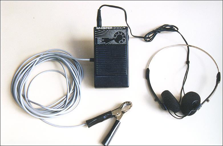
The design is based on the ‘Listen Up Portable Personal Sound Amplifier’ that you can find from lots of eBay sellers from just $7.

In the basic version of the detonation listening device, you’ll also need to add a decent pair of earphones or headphones, four metres of cable (eg shielded two-core microphone cable) and a battery clip.

In the more advanced version, add to that an on/off switch, 10-turn 10 kilo-ohm pot, a new box and revised battery arrangement.

Building the basic version


113326_10lo.jpg

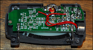
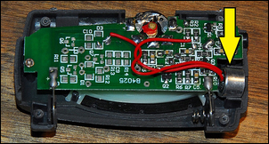
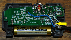
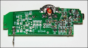
Open the box by first talking off the end caps (one covers the battery – a single AAA cell) to reveal four small screws. With it open, it should look like this.


113326_13lo.jpg

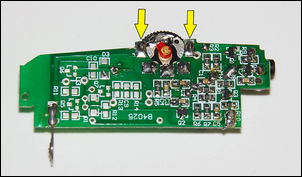
Note the microphone (arrowed) – both the fact that it is a large and relatively good quality unit, and that it is attached to the printed circuit board with flying leads. Unsolder the microphone and solder in place the new long shielded cable.


113326_21lo.jpg

Here are the new wires soldered into place. I also soldered the braid of the cable to the negative connection of the battery (arrowed), to provide better shielding of the signal. Make a suitable hole for the cable to escape and then close up the box.


113326_12lo.jpg

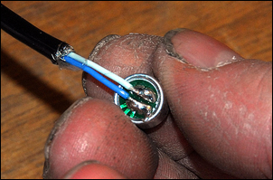
Solder the other end of the microphone cable to the microphone. Keep the polarity the same as original connections.


113326_5lo.jpg

Use hot melt glue or similar to mount the microphone to the inside arm of a metal battery clip, then cover in heatshrink.


113326_8lo.jpg

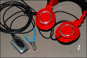
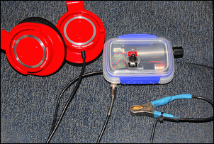
High quality, fully enclosed headphones will work best – but any decent quality earphones should also be fine. With fully enclosed headphones on, the sound quality is excellent.

The upgrade model
The basic version described above works very well indeed – but it has some areas where it could be even further improved.

Firstly, the single AAA battery, while having decent life, isn’t good enough if you’re doing a lot of tuning. Secondly, the on/off switch is incorporated in the volume switch and so you lose your volume setting every time you switch the device off. Finally, the volume control is very finicky to set to the precise listening level – and listening level is important when you’re trying to sort out different sounds.

Our improved version fixes each of these issues.

Please note that to build this improved version, you need slightly higher soldering skills than with the basic version, and having a solder sucker also helps.


113326_20lo.jpg

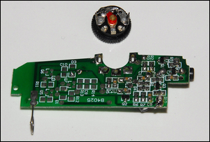
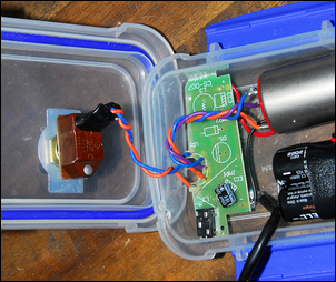
The first step in this version of the build is to remove the printed circuit board from the case. Take special note of the polarity of the battery connections.


113326_12lo.jpg

The microphone, microphone clip and microphone connections are then all made as with the basic version described above.


113326_15lo.jpg

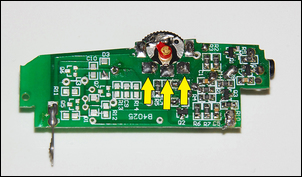
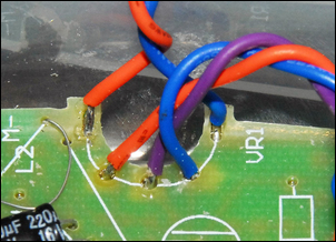
Look carefully at the on-board pot. These two connections are for the on/off switch….


113326_14lo.jpg

…and these three connections control the volume.


113326_16lo.jpg

Using a solder-sucker and a soldering iron, de-solder the pot so it can be removed.


113326_17lo.jpg

Carefully solder some short lengths of flexible insulated wire to each of the five positions – two for the switch and three for the pot. This view is from the other side of the board – the tinned wires have been pushed through the original holes and then soldered on the other side.


113326_18lo.jpg

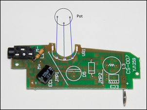
The pot connects like this. If you find that the pot works the wrong way (ie volume falls when it should rise), just reverse the two outer connections.


113326_3lo.jpg

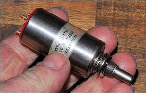
I used an impressively large multi-turn pot – but that’s just because I happened to have it. You need a 10 kilo-ohm pot, with as many turns as possible (eg 10 turns). A log pot would be nice but a normal linear one still works very well. You can use any knob you want on the pot.


113326_19lo.jpg

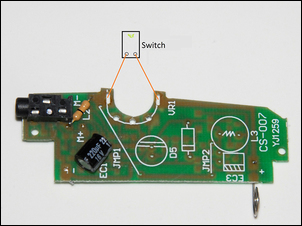
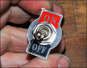
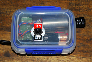
The on/off switch connects like this.


113326_6lo.jpg

The connections.


113326_22lo.jpg

Because the system works at only 1.5V, it’s hard to add an LED to show when the system is switched on. I therefore used a switch with a large on/off tag.


113326_2lo.jpg

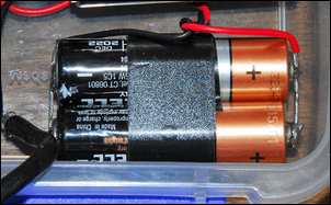
The next two steps are to build the device into a box, and add a better battery. For the battery I simply soldered two AA cells in parallel (NOT series) so that they provided the same voltage as original (ie 1.5V). The battery is connected to the original power connections – the switch then turns the device on and off normally. (Make sure you keep the correct polarity – the + connection is shown on the board.) You’ll need to unsolder the batteries to change them, but two AA cells like this should last for hundreds of hours.


113326_7lo.jpg

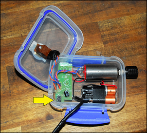
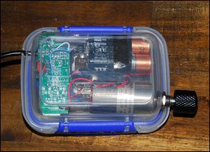
The whole lot is then mounted in a small kitchen container. Note how the headphone jack (arrowed) has been aligned with a hole in the container wall so that the headphones can still be plugged in.


113326_4lo.jpg

The bottom view….


113326_23lo.jpg

…and the top view.

Using It


113326_9lo.jpg

Using the detonation listener is very simple. You simply clip to the microphone to whatever you are interested in listening to. Noises are transmitted through the metalwork directly to the clip and microphone, making the device extremely sensitive. The 10-turn pot means you can set the volume level very finely – useful when you are trying to sort out different sounds.

To detect detonation, the clip is best placed directly on the block, in the type of place that the factory knock sensors are positioned - no surprise there! Adjust the volume control to give a comfortable loudness level, and sit back and listen. Over the clatter of pistons, valve gear, explosions and gearbox whines, detonation sounds like a sharp "splat!, splat!".

However, the device’s functions are not limited to this alone. Setting idle speed is easier when listening to the engine because you can better hear hunting; you can use it to ensure that over-run injector shut-off is working; and you can also use it to detect if on-off vacuum solenoids are operating as they should.

Note that it's best to listen from the passenger seat while someone else drives the car - that way, the driver can still hear emergency vehicles and concentrate on driving, not listening to strange sounds…

For its cost and effectiveness, this (along with a wide-band air/fuel ratio meter) is one of the best tuning tools you can have.
 
Back
Top