this is the type of challenge/upgrade I work on for the guys all the time, AND IM CERTAINLY NOT SUGGESTING YOU CAN,T REACH YOUR GOAL,THRU OTHER ROUTES, BUT THAT APPROACHING THE PROBLEM LOGICALLY ITS FAIRLY EASY TO PLAN YOUR GOALS AND COURSE TO ACHIEVE THEM,Ill make some suggestions but you'll make the choices. keep in mind the cam timing, compression ratio, head flow rates,rear gearing and stall speed MUST match 
http://www.bacomatic.org/~dw/engine/tw383/tw383.htm
first question Im usually asked is WHY build a 383-401, that's simple, you want to use the 350 block that came in the car to save money and make this a simple operation, the 383-401 strokers make excellent power and the increased displacement has advantages,(more total hp and a lower average rpm band) if a 350 makes 1.1 hp per cubic inch you have about 385hp, the same hp ratio in a 383 gives you about 425hp. and usually at about 300-400 rpm lower average rpm, that's easier on the valve train.
the first thing youll need to get strait in your mind is the realistic budget youll be willing to work with and that performance is basically the result of the power to weight ratio and HOW effectively you can get the power to the ground. keep in mind that for a street car your NOT building the engine for max peak power, your looking to build for the best average power/tq curve over the rpm range youll use most
AND THAT HAVING SLIGHTLY MORE HP THAN THE MINIMUM REQUIRED IS SMART, simply because you won,t always have the ideal tune or traction available,its silly to shoot for minimum levels yet its a waste of money to over build the engine, to levels you'll seldom use or even want, as theres always compromises in drive ability
ok first Id point out that its silly to build anything smaller than a 383 displacement simply because you'll make significantly greater total power from a larger engine than a smaller one,COSTS for a 383 are just not that much higher than a 350, and its TOTAL POWER not horsepower per cubic inch your interested in!
next,CORRECTLY MATCHING the cylinder heads, cam and compression ratio , to the rpm range where youll get the best results is where youll make most of your power potential.
think it thru before buying parts, and only sellect those components that match your goal,by far the most comon mistake is randomly sellecting mis-matched parts because you "GOT A DEAL"
ok lets look at your options, to keep costs reasonable we want to use what we can from your current engine but its insane to limit yourself to parts that restrict your potential power levels severly like the current heads,intake and rear gear ratio.
the formula for hp is (tq x rpm/5252=hp
example
450 ft lbs of torque at 3000rpm=257hp
450 ft lbs of torque at 6000rpm=514hp
because the torque is available at that higher RPM RATE and at the higher rpm using gearing the rotational force the engine supplied can be applied faster or slower to the rear tires
if your smart your not looking to spend a huge amount of cash but you do want a reasonably quick car,
a few calculations will quickly point out that your realy looking to have between 375-450 rear wheel hp, that basically translates into an engine making about 18% higher power at the flywheel, so lets assume or goal is a 450-500 hp engine, now your basic 383 will be correctly designed and matched to a rear gear ratio in the 3.73-4.11 rear gear so youll maximize the area in the torque curve that can give the best results, the 2800-6300rpm band. so thats where we NEED TOO concentrate our efforts. this should point out the stall speed of about 2800-3000rpm is ideal in this application to match your needs
a 383 with its 3.75" stroke and reasonably street able cam will be using a cam with between ABOUT 225-235 duration at .050 lift with a matching compression ratio in the 10:1-10.5:1 cpr range

look at this chart, it shows the ideal duration for best results at different rpm bands, well want the MINIMUM DURATION that will supply our needs thats going to be in the 220-230 range for street use,while the 230-235 range would be about ideal for power.but you'll loose street ability.
we quickly find that duration will match to a 10:1-10.5:1 cpr if we want to use pump gas.
why do I usually suggest a hydraulic roller cam?
read this
http://www.idavette.net/hib/camcon.htm
ok,now the CYLINDER HEADS and intake NEED to supply that RPM RANGE and DISPLACEMENT, youll want a set of heads that flow about 230cfm AT .500 lift at the MINIMUM and 250-270cfm is FAR better,to easily match that requirement.
http://www.jegs.com/webapp/wcs/stores/servlet/product2_10001_10002_760699_-1
http://airflowresearch.com/eliminator.php
http://www.compcams.com/Community/Articles/Details.asp?ID=1737510521
http://store.summitracing.com/partdetail.asp?autofilter=1&part=TFS-32400007&N=700+304524+115&autoview=sku
viewtopic.php?f=69&t=2145
those heads and that compression ratio, and cams Ill suggest will match the 3000rpm stall speed but youll need a 3.54:1-3.73:1 rear gear ratio to match.
cams like this
http://www.cranecams.com/?show=browseParts&action=partSpec&partNumber=119661&lvl=2&prt=5
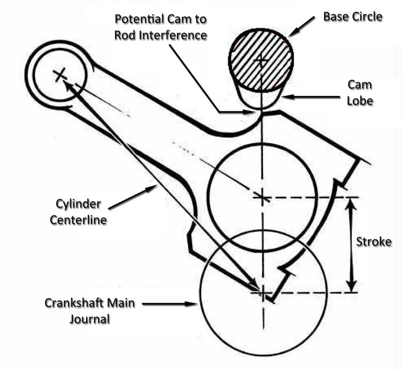
heres the SMALL BASE CAM I USE IN MY 383
NOTICE it has a .900 base circle
a small base circle gives more clearance because your cam lobe lift is the differance between the base circle and the lobe nose, lets assume a .500 lift on a chevy sb
they normally use a 1.5 ratio rocker so the cam lobe needs to be .3334 tall , so with a standard base circle the lobe nose swings in a circle thats about 1.766 in dia.
(
a small base circle cam like my crane with its .900 dia. with the same lobe would only spin in a circle thats about 1.568 in dia. giving about 0.100 inches MORE CLEARANCE TO THE POTENTIAL ROD/CAM CONTACT AREA
http://www.cranecams.com/?show=browseParts&action=partSpec&partNumber=119661&lvl=2&prt=5
this makes slightly better PEAK power, but was less streetable
http://www.crower.com/misc/cam_spec/cam_finder.php?part_num=00471&x=20&y=9
stroker kits
http://www.speedomotive.com/ps-522-85-383cid-mighty-mouse-budget-all-forged-stroker-kit.aspx
http://www.speedomotive.com/ps-525-85-391cid-all-forged-stroker-kit.aspx
installing a longer 3.75 stroke crank assembly
Ive built dozens of 383 and 396 sbc engines and the clearance can be done BY YOUR OWN HANDS with a standard HAND HELD drill and a few CARBIDE BURRS OR GRIND STONES in that drill in well under two hours if you take your time and total expense even if you need to buy that drill and burrs will be well under $50 total
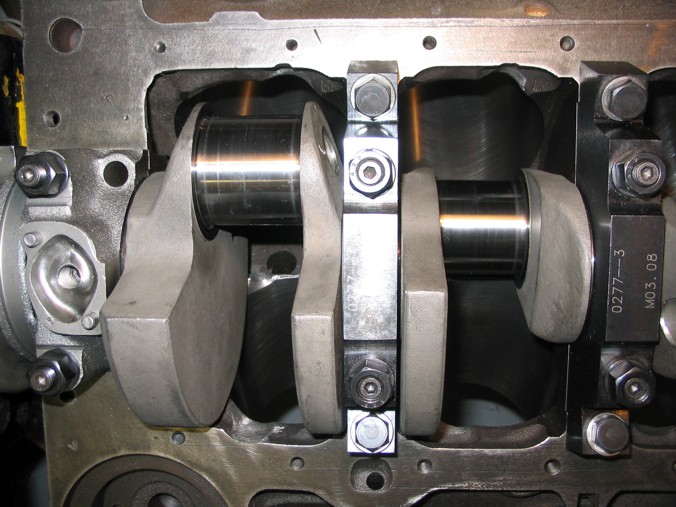
place you old bearings in the block an place the crank in those bearings after coating them with axle grease
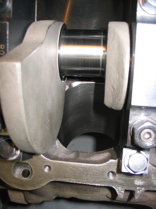
slowly rotate the crank and grind a minimum of .060 clearance anywhere the counter weights might touch the block and try NOT to grind more than about .070 any place it touches the block (use a JUMBO size paper clip as a gauge if you don,t have feeler gauges)
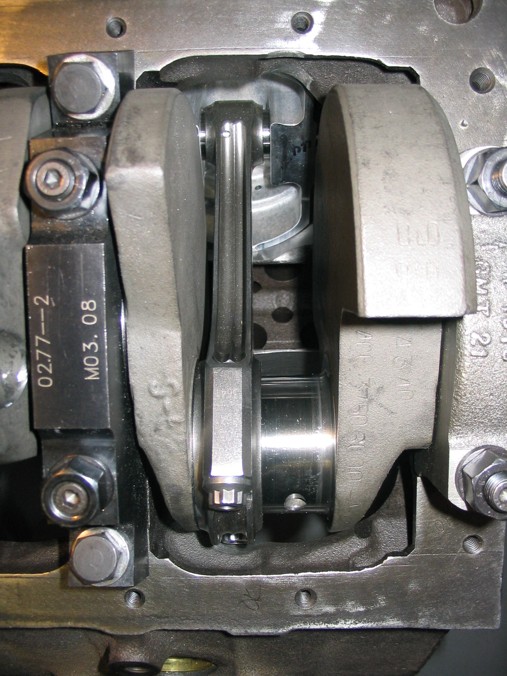
next assemble two connecting rods and pistons, one connecting rod and piston for the left one connecting rod and piston for the right, use old bearings coated with axle grease and no rings on the pistons, assemble them to the crank and grind anyplace the rods touch the block, grind minimum of .060 clearance and try NOT to grind more than about .070 any place the rods touche the block (use a LARGE size paper clip as a gauge if you don,t have feeler gauges)move them to the next journal and repeat until all 4 journals and 8 connecting rods clear. now assemble all eight rods and pistons without rings and install them in thier correct locations and recheck everything carefully.
next intall the cam and index it correctly with the timeing chain/gears, rotate the engine slowly and look for clearance issues, between the cam and rods/rod bolts ,youll need to use a small base cam if there are major clearance issues but in most cases if your cams lift and duration is under about 230 at .05 and .500 lift there should be minor if any clearance issues, usually the outside edge of a rod bolt head is the only area needing a touch up.
once everything clears, wash all the parts VERY CAREFULLY ,TWICE and re-oil then send out to be ballanced now you might ask why do that! well, first youll know its done correctly, and that a correctly built 383 will have a very significant hp and torque advantage over any similar 327 or 350
how much power I'll get.
that of couse depends on the combo, cpr, cam,ETC. but you can assume about a 40hp/40 ft lbs increase over a similarly built 350
some of the major factors in your engines potential power, is the volumetric efficiency (how efficiently you fill and empty the cylinders) and the octane of the fuel used, compression ratio and detonation limits,
With detonation, prevention the main factors are
Ignition timing
Quench
FUEL OCTANE
DCR
and cylinder heat level
you�ll be fairly safe if you stay under
8.5:1 dcr at 170f degrees
8.25 dcr at 180f degrees
7.8:1 dcr at 210f degrees
and keep the quench in the .036-.043 range
need a few pictures?
this may help
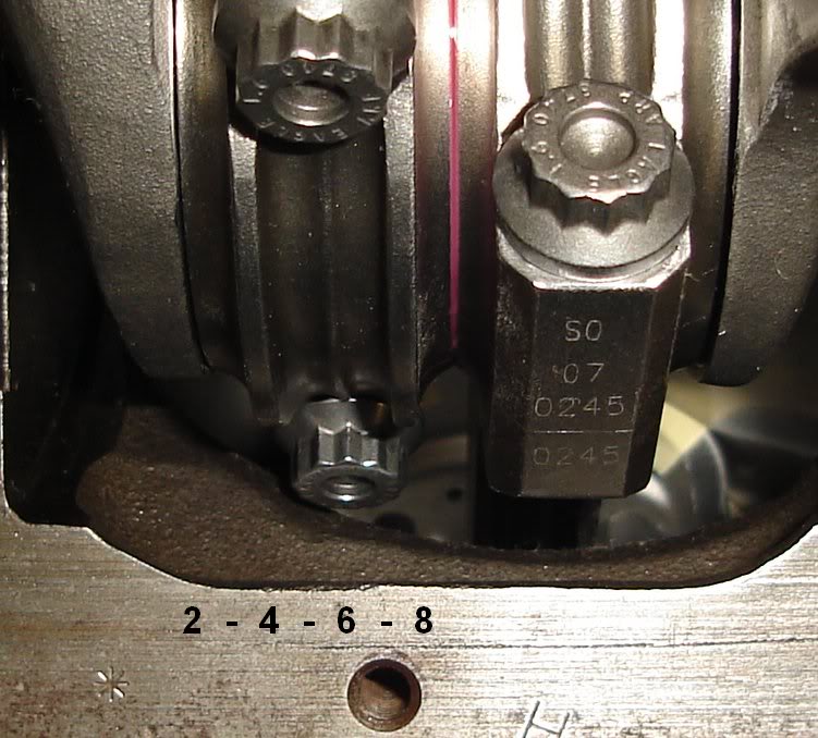
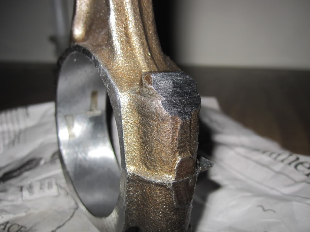
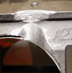
the comon areas are the area near the block oil pan rail where the rod bolts touch
and the lower inner cylinder walls and where the cam lobes touch the rod bolts upper shoulder on some types of rods, now you can,t grind on the cam, but you can grind the edge of the rod bolt and you can use a small base circle cam to give greater clearances
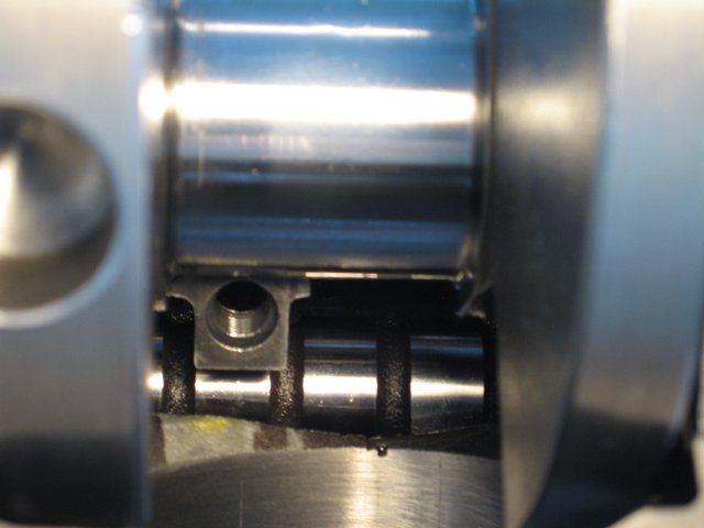
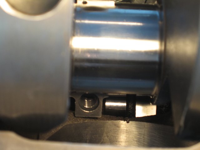
obvious interference
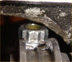
notice how the rod bolts come close to the cam bearings and cam lobes,as the pistons reach top dead canter in the bores, this clearance must be individually checked and should be no less than about .060 (generally you cam use a LARGE plastic tie-wrap
https://www.amazon.com/BuyCableTies...D=41U9CtmwOuL&preST=_SY300_QL70_&dpSrc=detail

placed between the cam lobe and connecting rod bolts or connecting rod shoulder areas to check clearances as the soft tie-wrap will not damage the cam lobe while you verify clearances)
QUENCH??
http://www.100megsfree4.com/dictionary/car-dicq.htm
quench area:
A zone in the combustion chamber where the piston at top dead center is very close to the cylinder head. Because the piston and cylinder head is cooler than the unburned part of the fuel-air mixture (i.e., end gas), they pull the heat from the end gas. Because the end gas is now cooler, detonation is quenched or reduced. However, the process does form unburned hydrocarbons.
SQUISH
An area in the combustion chamber of some engines where the piston squishes or squeezes part of the fuel-air mixture at the end of the compression stroke. As the piston approaches top dead center, the mixture is pushed out of the squish area and this promotes turbulence, further mixing of the fuel-air mixture and more efficient combustion
run less than about .035 thousands and at high rpm levels the pistons might hit the cylinder heads, run more than about .044 thousands the QUENCH effect of forcing the fuel air mix to the center of the cylinder from the cylinders edge area looses both speed and effectiveness, remember the quench area must be so tight that virtually all the fuel/air mix is forced (squished) into the center area and none is allowed to burn until its squirted into the burn area increasing turbulence and burn efficiency
in theory the much better quench, combined with the shorter more compact area the flame front needs to cover and the far higher turbulence combine to allow more of the pressure to build AFTER the crank passes TDC on the end of compression and beginning of the power stroke
its mostly an advantage in that you get a more even and FASTER burn in the cylinder and less chance of detonation, simply because both the lower time and faster pressure curves favor the ignition flame front vs detonation
look, it takes approximately 40 thousands of a second for the flame from the ignition to cross a 4.25" bore,at low rpms and still takes about 15 milliseconds at high RPM due to the much faster movement of the compressed fuel air mix in the cylinders, lets look at what that means
if the chevy plug is located 4/5ths of the way to one side that's a time of about 32 thousands for the pressure to build as the flame travels 3.4" in the chevy but in a compact combustion chamber it could only take the cylinder flame front less than 10-20 thousands of a second to travel acrossed the combustion chamber for a complete burn at low rpms, this of course speeds up as the swirl and turbulence increase with increased engine RPMs but the ratios stay similar. this results in more usable energy WORKING on the piston AFTER IT PASSES TOP DEAD CENTER ON THE POWER STROKE. BUT MODERN WEDGE combustion chambers use increased QUENCH to speed the flame front and lower the burn time combined with a smaller combustion chambers.
the differance may be easier to grasp if you think of the quench area as a significant part of the total combustion chamber voluum,thats forcing its potential fuel/air mix into the central combustion chamber as a jet of highly compressed F/A mix, like the differance between lighting a cup of gasoline by simply placing it next to a camp fire vs throwing it violently into a camp fire
383, do you clearance the 350 block, machine the crank, or both?
I hate to start a new thread when it seems that grumpy has exhaustively covered EVERYTHING when it comes to blocks and engine buildings already on this site, but this is sort of a specific question: I have been following a step by step on prepping my block to become a 383 build, and I am...
garage.grumpysperformance.com
first question Im usually asked is WHY build a 383-401, that's simple, you want to use the 350 block that came in the car to save money and make this a simple operation, the 383-401 strokers make excellent power and the increased displacement has advantages,(more total hp and a lower average rpm band) if a 350 makes 1.1 hp per cubic inch you have about 385hp, the same hp ratio in a 383 gives you about 425hp. and usually at about 300-400 rpm lower average rpm, that's easier on the valve train.
the first thing youll need to get strait in your mind is the realistic budget youll be willing to work with and that performance is basically the result of the power to weight ratio and HOW effectively you can get the power to the ground. keep in mind that for a street car your NOT building the engine for max peak power, your looking to build for the best average power/tq curve over the rpm range youll use most
AND THAT HAVING SLIGHTLY MORE HP THAN THE MINIMUM REQUIRED IS SMART, simply because you won,t always have the ideal tune or traction available,its silly to shoot for minimum levels yet its a waste of money to over build the engine, to levels you'll seldom use or even want, as theres always compromises in drive ability
ok first Id point out that its silly to build anything smaller than a 383 displacement simply because you'll make significantly greater total power from a larger engine than a smaller one,COSTS for a 383 are just not that much higher than a 350, and its TOTAL POWER not horsepower per cubic inch your interested in!
next,CORRECTLY MATCHING the cylinder heads, cam and compression ratio , to the rpm range where youll get the best results is where youll make most of your power potential.
think it thru before buying parts, and only sellect those components that match your goal,by far the most comon mistake is randomly sellecting mis-matched parts because you "GOT A DEAL"
ok lets look at your options, to keep costs reasonable we want to use what we can from your current engine but its insane to limit yourself to parts that restrict your potential power levels severly like the current heads,intake and rear gear ratio.
the formula for hp is (tq x rpm/5252=hp
example
450 ft lbs of torque at 3000rpm=257hp
450 ft lbs of torque at 6000rpm=514hp
because the torque is available at that higher RPM RATE and at the higher rpm using gearing the rotational force the engine supplied can be applied faster or slower to the rear tires
if your smart your not looking to spend a huge amount of cash but you do want a reasonably quick car,
a few calculations will quickly point out that your realy looking to have between 375-450 rear wheel hp, that basically translates into an engine making about 18% higher power at the flywheel, so lets assume or goal is a 450-500 hp engine, now your basic 383 will be correctly designed and matched to a rear gear ratio in the 3.73-4.11 rear gear so youll maximize the area in the torque curve that can give the best results, the 2800-6300rpm band. so thats where we NEED TOO concentrate our efforts. this should point out the stall speed of about 2800-3000rpm is ideal in this application to match your needs
a 383 with its 3.75" stroke and reasonably street able cam will be using a cam with between ABOUT 225-235 duration at .050 lift with a matching compression ratio in the 10:1-10.5:1 cpr range
look at this chart, it shows the ideal duration for best results at different rpm bands, well want the MINIMUM DURATION that will supply our needs thats going to be in the 220-230 range for street use,while the 230-235 range would be about ideal for power.but you'll loose street ability.
we quickly find that duration will match to a 10:1-10.5:1 cpr if we want to use pump gas.
why do I usually suggest a hydraulic roller cam?
read this
http://www.idavette.net/hib/camcon.htm
ok,now the CYLINDER HEADS and intake NEED to supply that RPM RANGE and DISPLACEMENT, youll want a set of heads that flow about 230cfm AT .500 lift at the MINIMUM and 250-270cfm is FAR better,to easily match that requirement.
http://www.jegs.com/webapp/wcs/stores/servlet/product2_10001_10002_760699_-1
http://airflowresearch.com/eliminator.php
http://www.compcams.com/Community/Articles/Details.asp?ID=1737510521
http://store.summitracing.com/partdetail.asp?autofilter=1&part=TFS-32400007&N=700+304524+115&autoview=sku
viewtopic.php?f=69&t=2145
those heads and that compression ratio, and cams Ill suggest will match the 3000rpm stall speed but youll need a 3.54:1-3.73:1 rear gear ratio to match.
cams like this
http://www.cranecams.com/?show=browseParts&action=partSpec&partNumber=119661&lvl=2&prt=5
heres the SMALL BASE CAM I USE IN MY 383
NOTICE it has a .900 base circle
a small base circle gives more clearance because your cam lobe lift is the differance between the base circle and the lobe nose, lets assume a .500 lift on a chevy sb
they normally use a 1.5 ratio rocker so the cam lobe needs to be .3334 tall , so with a standard base circle the lobe nose swings in a circle thats about 1.766 in dia.
(
a small base circle cam like my crane with its .900 dia. with the same lobe would only spin in a circle thats about 1.568 in dia. giving about 0.100 inches MORE CLEARANCE TO THE POTENTIAL ROD/CAM CONTACT AREA
http://www.cranecams.com/?show=browseParts&action=partSpec&partNumber=119661&lvl=2&prt=5
this makes slightly better PEAK power, but was less streetable
http://www.crower.com/misc/cam_spec/cam_finder.php?part_num=00471&x=20&y=9
stroker kits
http://www.speedomotive.com/ps-522-85-383cid-mighty-mouse-budget-all-forged-stroker-kit.aspx
http://www.speedomotive.com/ps-525-85-391cid-all-forged-stroker-kit.aspx
installing a longer 3.75 stroke crank assembly
Ive built dozens of 383 and 396 sbc engines and the clearance can be done BY YOUR OWN HANDS with a standard HAND HELD drill and a few CARBIDE BURRS OR GRIND STONES in that drill in well under two hours if you take your time and total expense even if you need to buy that drill and burrs will be well under $50 total
place you old bearings in the block an place the crank in those bearings after coating them with axle grease
slowly rotate the crank and grind a minimum of .060 clearance anywhere the counter weights might touch the block and try NOT to grind more than about .070 any place it touches the block (use a JUMBO size paper clip as a gauge if you don,t have feeler gauges)
next assemble two connecting rods and pistons, one connecting rod and piston for the left one connecting rod and piston for the right, use old bearings coated with axle grease and no rings on the pistons, assemble them to the crank and grind anyplace the rods touch the block, grind minimum of .060 clearance and try NOT to grind more than about .070 any place the rods touche the block (use a LARGE size paper clip as a gauge if you don,t have feeler gauges)move them to the next journal and repeat until all 4 journals and 8 connecting rods clear. now assemble all eight rods and pistons without rings and install them in thier correct locations and recheck everything carefully.
next intall the cam and index it correctly with the timeing chain/gears, rotate the engine slowly and look for clearance issues, between the cam and rods/rod bolts ,youll need to use a small base cam if there are major clearance issues but in most cases if your cams lift and duration is under about 230 at .05 and .500 lift there should be minor if any clearance issues, usually the outside edge of a rod bolt head is the only area needing a touch up.
once everything clears, wash all the parts VERY CAREFULLY ,TWICE and re-oil then send out to be ballanced now you might ask why do that! well, first youll know its done correctly, and that a correctly built 383 will have a very significant hp and torque advantage over any similar 327 or 350
how much power I'll get.
that of couse depends on the combo, cpr, cam,ETC. but you can assume about a 40hp/40 ft lbs increase over a similarly built 350
some of the major factors in your engines potential power, is the volumetric efficiency (how efficiently you fill and empty the cylinders) and the octane of the fuel used, compression ratio and detonation limits,
With detonation, prevention the main factors are
Ignition timing
Quench
FUEL OCTANE
DCR
and cylinder heat level
you�ll be fairly safe if you stay under
8.5:1 dcr at 170f degrees
8.25 dcr at 180f degrees
7.8:1 dcr at 210f degrees
and keep the quench in the .036-.043 range
need a few pictures?
this may help
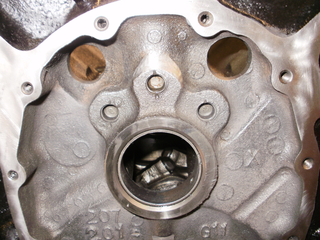
the comon areas are the area near the block oil pan rail where the rod bolts touch
and the lower inner cylinder walls and where the cam lobes touch the rod bolts upper shoulder on some types of rods, now you can,t grind on the cam, but you can grind the edge of the rod bolt and you can use a small base circle cam to give greater clearances
obvious interference
notice how the rod bolts come close to the cam bearings and cam lobes,as the pistons reach top dead canter in the bores, this clearance must be individually checked and should be no less than about .060 (generally you cam use a LARGE plastic tie-wrap
https://www.amazon.com/BuyCableTies...D=41U9CtmwOuL&preST=_SY300_QL70_&dpSrc=detail
placed between the cam lobe and connecting rod bolts or connecting rod shoulder areas to check clearances as the soft tie-wrap will not damage the cam lobe while you verify clearances)
QUENCH??
http://www.100megsfree4.com/dictionary/car-dicq.htm
quench area:
A zone in the combustion chamber where the piston at top dead center is very close to the cylinder head. Because the piston and cylinder head is cooler than the unburned part of the fuel-air mixture (i.e., end gas), they pull the heat from the end gas. Because the end gas is now cooler, detonation is quenched or reduced. However, the process does form unburned hydrocarbons.
SQUISH
An area in the combustion chamber of some engines where the piston squishes or squeezes part of the fuel-air mixture at the end of the compression stroke. As the piston approaches top dead center, the mixture is pushed out of the squish area and this promotes turbulence, further mixing of the fuel-air mixture and more efficient combustion
run less than about .035 thousands and at high rpm levels the pistons might hit the cylinder heads, run more than about .044 thousands the QUENCH effect of forcing the fuel air mix to the center of the cylinder from the cylinders edge area looses both speed and effectiveness, remember the quench area must be so tight that virtually all the fuel/air mix is forced (squished) into the center area and none is allowed to burn until its squirted into the burn area increasing turbulence and burn efficiency
in theory the much better quench, combined with the shorter more compact area the flame front needs to cover and the far higher turbulence combine to allow more of the pressure to build AFTER the crank passes TDC on the end of compression and beginning of the power stroke
its mostly an advantage in that you get a more even and FASTER burn in the cylinder and less chance of detonation, simply because both the lower time and faster pressure curves favor the ignition flame front vs detonation
look, it takes approximately 40 thousands of a second for the flame from the ignition to cross a 4.25" bore,at low rpms and still takes about 15 milliseconds at high RPM due to the much faster movement of the compressed fuel air mix in the cylinders, lets look at what that means
if the chevy plug is located 4/5ths of the way to one side that's a time of about 32 thousands for the pressure to build as the flame travels 3.4" in the chevy but in a compact combustion chamber it could only take the cylinder flame front less than 10-20 thousands of a second to travel acrossed the combustion chamber for a complete burn at low rpms, this of course speeds up as the swirl and turbulence increase with increased engine RPMs but the ratios stay similar. this results in more usable energy WORKING on the piston AFTER IT PASSES TOP DEAD CENTER ON THE POWER STROKE. BUT MODERN WEDGE combustion chambers use increased QUENCH to speed the flame front and lower the burn time combined with a smaller combustion chambers.
the differance may be easier to grasp if you think of the quench area as a significant part of the total combustion chamber voluum,thats forcing its potential fuel/air mix into the central combustion chamber as a jet of highly compressed F/A mix, like the differance between lighting a cup of gasoline by simply placing it next to a camp fire vs throwing it violently into a camp fire
Last edited by a moderator: