http://www.zfdoc.com/
http://www.zfdoc.com/c4beamplate.htm
http://www.zfdoc.com/c4beamplatefeedback.htm
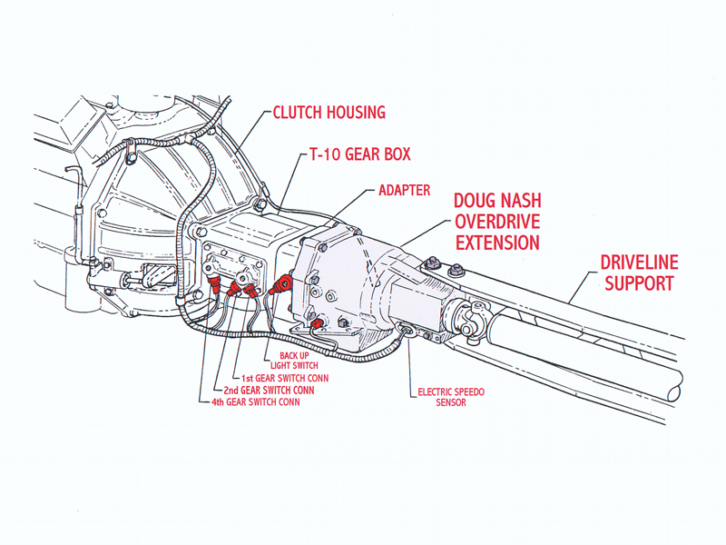
These multi-purpose driveline support reinforcement plates can be used on all 1984 through 1996 model year (C4 or 4th Generation) Corvettes. We have found that most C4 Corvettes inherently experience a slight amount of twisting at the fastening points of the support beam to the transmission and differential housing connection surfaces. Although fastened with high grade bolts, self-locking nuts and adhered with factory sealant, the driveline components of the C4 Corvette still experience some level of counterforce load-induced lateral deflection between the members while under heavy loading. This allowance of flex in the driveline beam fastening joints creates a condition where the chassis structure must additionally contend with. One common side effect of this phenomenon is where the rear of the vehicle tends to kick out to the right during aggressive high RPM gear shifting. Notice that the C5 or 1997 and newer Corvette was redesigned so that lateral deflection of the driveline is practically non existent. The C5 Corvette driveline consists of a drive shaft within a tube that has a bell housing fused to each end.
Q) How does lateral deflection between the driveline members affect the vehicle handling?.
A) The immediate area of the driveline beam around the bolt and nut heads where the beam fastens to the transmission and differential are prone t flexing a finite amount. With the slightest amount of flex or deflection occurring at these joints, counter-force torsion energy is off-loaded to the chassis. This brief spike of counterforce energy causes unnecessary deviation of the suspension planes. A brief change in the drive wheel thrust angles is the root cause for the C4’s inherent response of the rear end kicking out to the right when aggressively shifting during heavy acceleration.
Q) How do the C4 Beam Plates improve the vehicle handling?
A) By installing the ZR51 Performance C4 Beam Plates, the driveline system becomes more rigid and less apt to affect the suspension system during extreme loading.
* ‘C4 Beam Plates’ is a registered trademark of ZR51 Performance and is patent pending.
C4 Beam Plate Installation Instructions: (P/N 1052C4BP) (Now comes with 2 driveline clearance checking blocks.)
Raise vehicle and suitably support.
Remove partial or complete exhaust system if necessary to achieve clearance for removal of driveline support fasteners.
Support transmission and ready a secondary support device beneath the differential. NOTE: Removal and installation of the driveline support fastening bolts normally requires manipulating of the transmission and differential mount points. A second jack or lifting device is recommended.
Remove support beam fasteners, placing nuts and washers aside. (Do not re-use washers for they will not allow enough thread-depth penetration for the locking nuts to fasten securely).
Clean the upper and lower surface area where the C4 Beam Plates will be seated.
Carefully work the Driveline beam away from the Differential and extension housing enough to inspect the contact surfaces. Any surface irregularities must be removed.
Carefully restore Driveline beam to its original location (Included are 2 small sticks of metal that can be used in the next step as clearance "go no-go" gages for checking the support beam location/clearance within the tunnel.
Insert bolts through lower plates noting that the front lower plate has a relieved corner for speedometer bulkhead clearance. Position the plates (w/nuts) at their proper locations on top of Driveline beam. Insert bolts (w/lower plates) through the holes and hand start the threads by 1 turn into the top deflection plate.
ALIGN DRIVELINE COMPONENTS: Take the following measurements directly above and to the right of the Propeller shaft front yolk universal joint. To ensure proper alignment of the driveline, a clearance of 45 mm +/- 6mm (1.77 in. +/- 0.236 in.) must be maintained between the top of the support to the underbody and a clearance of 28 mm+/-6 mm (1.1 in. +/- 0.236 in.) from the right side (passenger side of vehicle) of the support to the side wall.
Tighten support bolts at carrier to 80 Nm (59 lb. ft.)
Tighten support bolts at transmission to 50 Nm (37 lb. ft.).
Remove transmission support(s), install exhaust (if removed), and lower vehicle.
http://www.zfdoc.com/c4beamplate.htm
http://www.zfdoc.com/c4beamplatefeedback.htm
These multi-purpose driveline support reinforcement plates can be used on all 1984 through 1996 model year (C4 or 4th Generation) Corvettes. We have found that most C4 Corvettes inherently experience a slight amount of twisting at the fastening points of the support beam to the transmission and differential housing connection surfaces. Although fastened with high grade bolts, self-locking nuts and adhered with factory sealant, the driveline components of the C4 Corvette still experience some level of counterforce load-induced lateral deflection between the members while under heavy loading. This allowance of flex in the driveline beam fastening joints creates a condition where the chassis structure must additionally contend with. One common side effect of this phenomenon is where the rear of the vehicle tends to kick out to the right during aggressive high RPM gear shifting. Notice that the C5 or 1997 and newer Corvette was redesigned so that lateral deflection of the driveline is practically non existent. The C5 Corvette driveline consists of a drive shaft within a tube that has a bell housing fused to each end.
Q) How does lateral deflection between the driveline members affect the vehicle handling?.
A) The immediate area of the driveline beam around the bolt and nut heads where the beam fastens to the transmission and differential are prone t flexing a finite amount. With the slightest amount of flex or deflection occurring at these joints, counter-force torsion energy is off-loaded to the chassis. This brief spike of counterforce energy causes unnecessary deviation of the suspension planes. A brief change in the drive wheel thrust angles is the root cause for the C4’s inherent response of the rear end kicking out to the right when aggressively shifting during heavy acceleration.
Q) How do the C4 Beam Plates improve the vehicle handling?
A) By installing the ZR51 Performance C4 Beam Plates, the driveline system becomes more rigid and less apt to affect the suspension system during extreme loading.
* ‘C4 Beam Plates’ is a registered trademark of ZR51 Performance and is patent pending.
C4 Beam Plate Installation Instructions: (P/N 1052C4BP) (Now comes with 2 driveline clearance checking blocks.)
Raise vehicle and suitably support.
Remove partial or complete exhaust system if necessary to achieve clearance for removal of driveline support fasteners.
Support transmission and ready a secondary support device beneath the differential. NOTE: Removal and installation of the driveline support fastening bolts normally requires manipulating of the transmission and differential mount points. A second jack or lifting device is recommended.
Remove support beam fasteners, placing nuts and washers aside. (Do not re-use washers for they will not allow enough thread-depth penetration for the locking nuts to fasten securely).
Clean the upper and lower surface area where the C4 Beam Plates will be seated.
Carefully work the Driveline beam away from the Differential and extension housing enough to inspect the contact surfaces. Any surface irregularities must be removed.
Carefully restore Driveline beam to its original location (Included are 2 small sticks of metal that can be used in the next step as clearance "go no-go" gages for checking the support beam location/clearance within the tunnel.
Insert bolts through lower plates noting that the front lower plate has a relieved corner for speedometer bulkhead clearance. Position the plates (w/nuts) at their proper locations on top of Driveline beam. Insert bolts (w/lower plates) through the holes and hand start the threads by 1 turn into the top deflection plate.
ALIGN DRIVELINE COMPONENTS: Take the following measurements directly above and to the right of the Propeller shaft front yolk universal joint. To ensure proper alignment of the driveline, a clearance of 45 mm +/- 6mm (1.77 in. +/- 0.236 in.) must be maintained between the top of the support to the underbody and a clearance of 28 mm+/-6 mm (1.1 in. +/- 0.236 in.) from the right side (passenger side of vehicle) of the support to the side wall.
Tighten support bolts at carrier to 80 Nm (59 lb. ft.)
Tighten support bolts at transmission to 50 Nm (37 lb. ft.).
Remove transmission support(s), install exhaust (if removed), and lower vehicle.