c3 & c4 corvette vacuum diagrams

grumpyvette

Administrator
Staff member
c3vacuum1.jpg


http://www.corvette-101.com/vacuum.htm
http://garage.grumpysperformance.co...-rather-than-jumping-in-with-both-feet.14918/
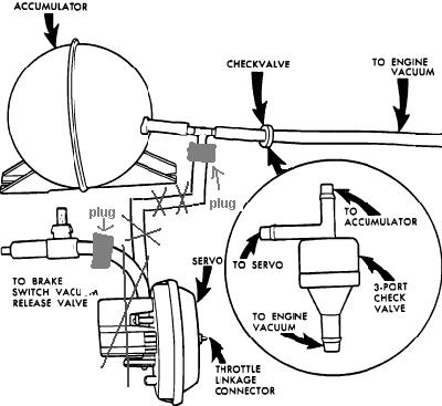
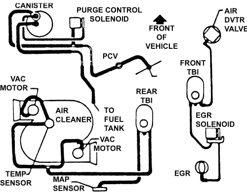
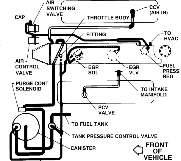
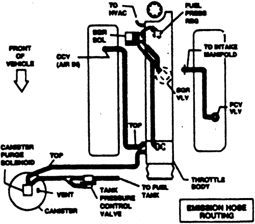
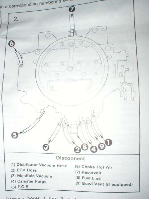
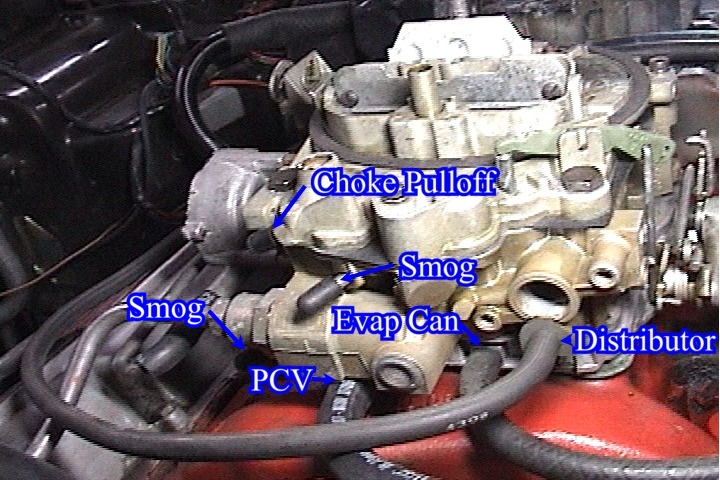
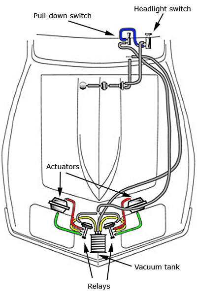
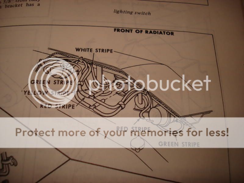
labeling connections

viewtopic.php?f=50&t=6098

c3vacuum2.jpg

81vacdiag.jpg

http://www.corvettefever.com/howto/53360/index.html
CarbFrontVacuumFitings.jpg

If you want confirmation for a certain year corvette then Chiltons repair manual, or a chevy shop manual
usually has several diagrams for each year and configuration:


c3vacuum3.jpg


if you break a line or can,t find a line location, you should be easily able to fabricate a fully functional replacement line, if you want to buy a direct replacement call these guys

http://www.ecklers.com/search.asp?actio ... chHistory=

http://www.ecklers.com/search.asp?actio ... chHistory={CE049489-2F7F-4AC3-8519-6219AF833BE6}^^Keyword%3A+vacuum+line^^free_text+%3D+%22vacuum+line%22+%3B+

related info
http://www.mamotorworks.com/corvette?frame=3.3850

http://www.vette2vette.com/

http://www.google.com/imgres?imgurl=htt ... 2&ct=image

vacuumdiagram.jpg


c3vacuum4.jpg


80-82vacuum.png


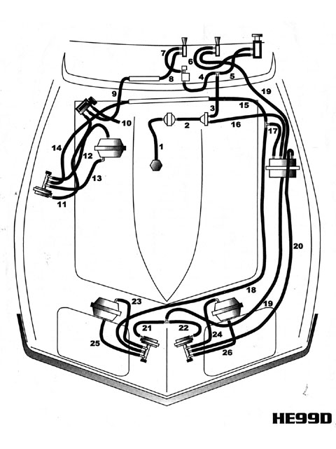
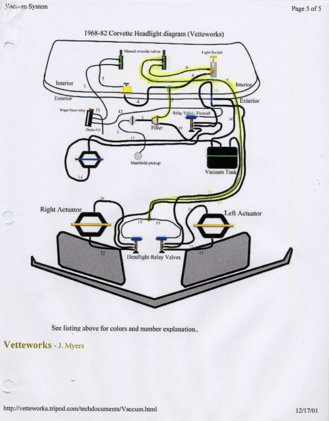
http://vetteworks.tripod.com/techdocuments/Vaccum.html

http://www.docrebuild.com/dr-r-web/SPARK2.pdf
is_it_right_1981_vacuum_system_diagram.JPG


c3vacuum5.jpg


Vacum_Secmatic.jpg


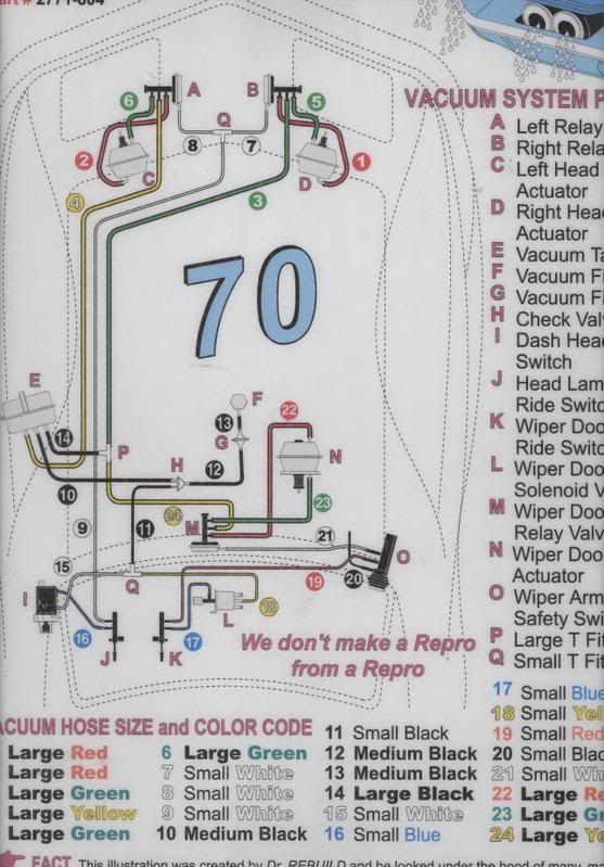
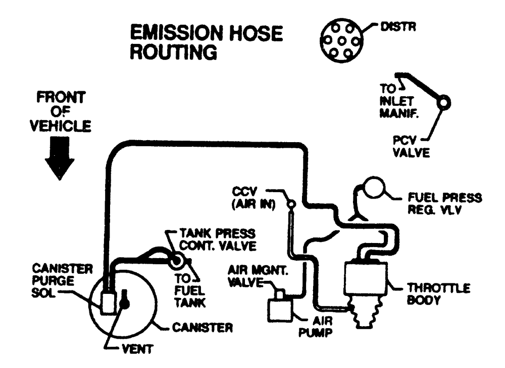
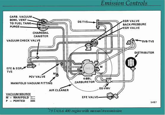
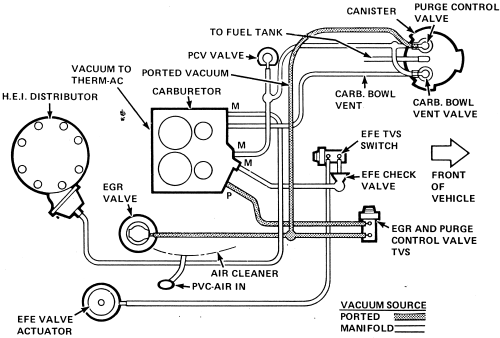
this may help some guys

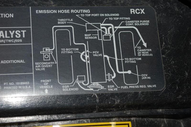
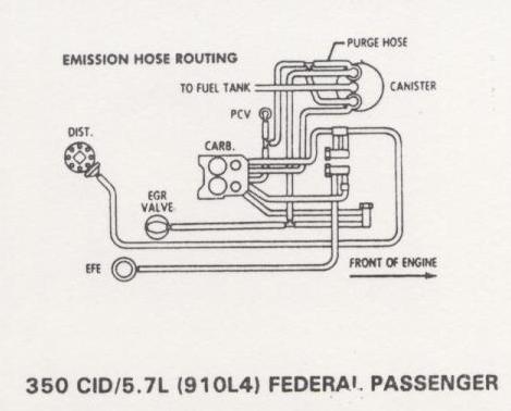
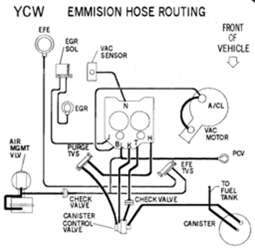
here are the diagrams if someone wants em :)


DSC08531.jpg


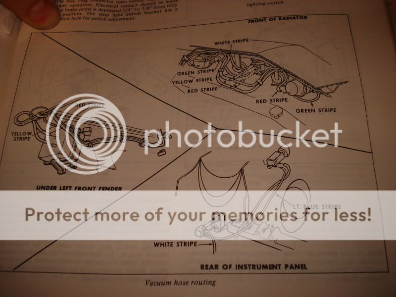
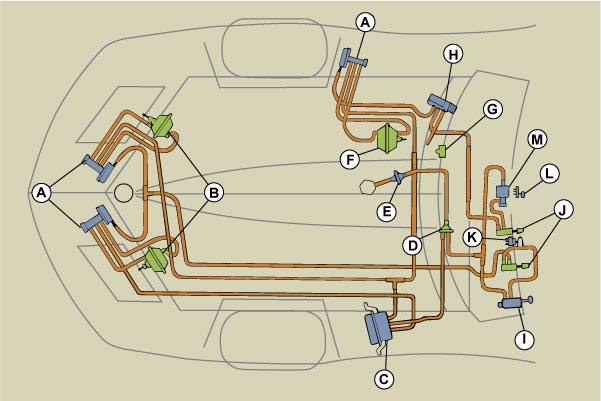
and vacuum lines up closer:
DSC08532.jpg
 
Last edited by a moderator:
Re: c3 corvette vacuum diagrams
0900c1528008fdc5.gif


cruise control vacuum lines for c4 corvette
47625702d1215002059-want-to-remove-cruise-control-vacuum-lines-cruisejp.jpg

c4 corvettes
link to sensor info you might need

posting.php?mode=edit&f=80&p=1025

http://chevythunder.com/fuel%20injectio ... 20DIAGRAMS
1984
19841vac.gif


1985-91
vacuumlines.gif

1992-96

1992-96vac.gif

vacuum.jpg

48180634d1501790797-1995-convertible-lt1-vacuum-line-routing-diagram-vacuumdiagram002large.jpg

VACUUM LINE DIAGRAMS

This page shows the most common vacuum line diagrams for stock TPI setups:


1985-86%205.0L%20TPI%20vacuum%20diagram.gif


The diagram above is for 1985-1986 5.0L F-body (Camaro/Firebird) MAF TPI

1985%202.8L%20MPI%20vacuum%20diagram.gif


1985 2.8L V6 MFI Camaro-Firebird Vacuum Line Diagram

1985%20Corvette%20vac.%20dia.gif


1985 Corvette 5.7L TPI Vacuum Diagram

1986-89%20%202.8L%20MPI.gif


1986-89 2.8L V6 MFI Camaro-Firebird Vacuum Line Diagram

1987-89%205.0%20&%205.7L%20TPI.gif


1986-1989 5.0 and 5.&L TPI Vacuum Line Diagram

.
1988-92%205.0L%20TBI%20man.%20trans.gif


1988-92 5.0L TBI Camaro-Firebird Vacuum Line Diagram. Manual trans

1988-92%205.0L%20TBI%20auto%20trans.gif


1988-92 5.0L TBI Camaro-Firebird Vacuum Line Diagram. Auto. trans

1990-91%20Corvette%20vac.%20dia.gif


1990-91 Corvette 5.7L Vacuum Line Diagram

1990-92%205.0%20&%205.7L%20TPI.gif


This diagram is for 1990-92 F-body (Camaro/Firebird) Speed density TPI

1990-92%203.1L%20MPI.gif


1990-92 3.1L V6 MFI Camaro-Firebird Vacuum Diagrams
 
Last edited by a moderator:
OMG, I think you just saved me an insane amount of time!

I just got my car back after getting headers installed and now it idles TERRIBLY and I can hear the dreaded vacuum leak hissing sound. They removed the SMOG pump as it's obviously not doing anything without the air recirculation ports in the stock manifolds, but I'm guessing that they didn't plug the vacuum line.

The diagrams showing where the smog system's vacuum lines go with a stock QJet I think will come in VERY handy in tracking this down.


Adam
 
Hey Grumpy, thanks for the work you put out over gathering all the vacuum schematics. I was lucky that the owner before me took care of the headlight and wiper door system on my '71, they work to near perfection. Many don't know that there were Rolling production line changes to the 69,70 and 71 model yrs. for the vacuum system.
The only thing that needs some attention now is the secret headlight washers that only ran in production until the beginning of the second half of 1971. Ira can have the fun that goes with sorting that out!
Along with a dozen or so small features there are a few little known details not finishing the second half of 71s production and gone by the 72 model year. There is no where that I know of that lists all these items until you look at the NCRS Judging manual specifically written for 1970 - 1972 Stingrays.
 
Can anyone explain to me why the heck there are so many different diameters of vacuum hose on our cars? Vacuum is vacuum; the diameter of the hose shouldn't change the amount of vacuum....
 
Can anyone explain to me why the heck there are so many different diameters of vacuum hose on our cars? Vacuum is vacuum; the diameter of the hose shouldn't change the amount of vacuum....
That's a great question.
Think of an engine as a big air pump. During combustion the piston down stroke is pulling in air at a rate that is determined by the inlet source such as a throttlebody and it's opening size relative to the cylinder's capacity. You have the greatest amount of work for the engine to pull in air behind a closed throttle plate (high vacuum)(small hose). Opening the throttle plate (a large hose) and engine work (vacuum) is decreased as the air pressure differential becomes damped behind the throttle plate due to the abundant ambient air supply in front of the throttle plate.
Different mechanical devises with actuation derived by vacuum may have different vacuum (and timing) needs. The greater the size hose, the lower the vacuum will be in a given amount of time. A small hose will provide a higher pressure over a shorter period of time.
So different sizes and lengths in vacuum lines are needed for operational management. Keep in mind when purchasing rubber hose that it must be vacuum rated so that the hose does not collapse under high vacuum and each fitting and excess length creates friction as well as restrictions. Avoid the many ways lines get pinched.
I really need to clean this up. I'll get a better explanation later when I can keep my eyes open. LOL!
 
Last edited:
Back
Top