c4 vette alignment specs

Grumpy

The Grumpy Grease Monkey mechanical engineer.
Staff member

related linked info
,
skipping reading through, the links reduces your chances of finding the info,
YOU MAY NEED!

http://garage.grumpysperformance.com/index.php?threads/upgrading-the-suspension-on-a-c-4.483/

https://tech.corvettecentral.com/2011/07/wheel-alignment-specs/

http://www.superchevy.com/how-to/vemp-0012-wheel-alignment-c4-corvette/

http://cartechstuff.blogspot.com/2013/02/c4-corvette-alignment.html

http://www.eurovettes.com/suspension_settings.htm

https://www.ecklerscorvette.com/1985+chevy+corvette.html?cat=1177&ea_a=&ea_bc=&ea_c=suspension-and-chassis.html&ea_path=-ymm%3d%271985%7eCHEVROLET%7eCORVETTE%27

http://www.superchevy.com/how-to/corp-0708-c4-corvette-suspension/

https://tech.corvettecentral.com/2013/11/c4-suspension-overview/

http://garage.grumpysperformance.co...ing-the-correct-tools-helps.12466/#post-75831

http://garage.grumpysperformance.co...hub-c4-corvette-replacement.10263/#post-41247

http://garage.grumpysperformance.com/index.php?threads/wheel-bearing-replacement.3128/#post-8340

https://www.corvettemods.com/Suspension_c_510.html

http://garage.grumpysperformance.co...mport-bearings-bushings-etc.13046/#post-67874

https://www.corvettemods.com/C4-Cor...ete-Front-Suspension-Rebuild-Kit-_p_8842.html

https://www.rockauto.com/

https://www.vette2vette.com/

https://www.ecklerscorvette.com/c4-parts.html

http://garage.grumpysperformance.com/index.php?threads/under-car-safety.26/

http://garage.grumpysperformance.co...c4-corvette-wheel-tech-info.12099/#post-72999

shop for suspension and wheel bearings and hubs and shocks , springs very carefully there is a great deal of comparatively low priced absolute junk quality components listed for sale for corvettes.
buying and using , only name brand, well respected and when available American made parts will save you more cash and induce far less problems, in the long term

http://garage.grumpysperformance.com/index.php?threads/upgrading-the-suspension-on-a-c-4.483/

if you look through the ROCKAUTO , ECKLERs , etc. catalog's ,
for example you'll frequently find prices that range from absurdly cheap too fairly high, but you can bet your last dime the cheaper crap won,t match the quality, clearances and proper metallurgy, buy the higher priced, name brand premium parts or youll find out why I suggested you do so rather rapidly in many cases


https://www.rockauto.com/en/catalog...350cid+v8,1041208,suspension,ball+joint,10070
vetal1.jpg

vetal2.png

vetal3.jpg

vetal4.gif

vettesu7.jpg


c4 alignment specs (Bluewasp)
VetteBrakes recommends straight from their 2002 catalog page6:

Daily Street:
Front: Toe = 1/32" in
Camber = 0 degrees
Caster = 5-7 degrees positive
Rear: Toe = 1/8" in
Camber = 0 degrees

Advanced Street:
Front: Toe = 0"
Camber = 1/4 degree negative
Caster = 5-7 degrees positive
Rear: Toe = 1/8" in
Camber = 1/2 degree negative

Autocross baseline:
Front: Toe = 3/16" out
Camber = 1 1/2 - 3 degrees negative
Caster = 4-5 degrees positive
Rear: Toe = 1/16" in
Camber = 3/4 - 2 1/2 degrees negative

Track baseline:
Front: Toe = 0 - 1/16" out
Camber = 1 - 3 degrees negative
Caster = 4-7 degrees positive
Rear: Toe = 1/8" in
Camber = 3/4 - 2 1/2 degrees negative


if you have clear related photos or info on the parts you bought and installed ,
and the quality or lack of quality please post the info,
so others are warned or benefit from your experience,
 
Last edited:

http://tech.corvettecentral.com/2013/11/c4-suspension-overview/
C4 Suspension Overview


This is the first installment of a C4 suspension overview series. Click to view the second article, Click to view the third article

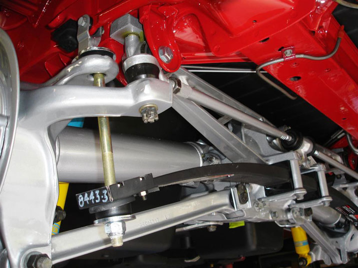
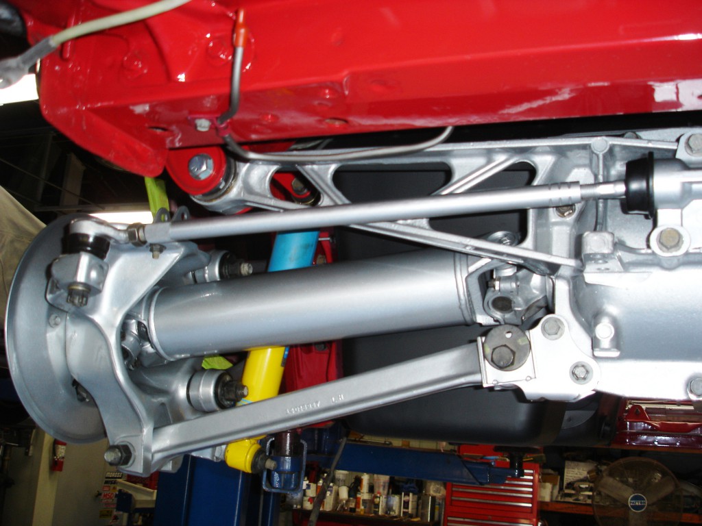
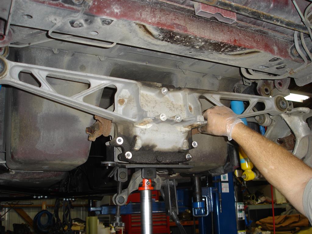
The fourth generation Corvette was a radical departure from General Motors early Corvette engineering. It eliminated a perimeter frame to support the suspension and driveline. Two front frame rails integrated into the first ever Corvette uni-body construction. This made for an interesting driveline mounting installation. The front suspension subframe was bolted to the frame rails while providing engine mounting points. The lack of a transmission crossmember added another twist, with a torque arm supporting the transmission and connecting it directly to the differential. The differential was mounted with two large bushings at the outer uni-body rear frame area. Rear vehicle weight was supported by a transverse spring that bolted directly to the differential rear cover.


The design allowed entire suspension and driveline installation/removal by simply removing sixteen bolts. The body (uni-body) structure could be dropped down on the assembled chassis and be a rolling C4 Corvette within minutes on the assembly line. Unfortunately, the rear suspension was not much different than the C2-C3 Corvette, with the suspension pivoting on the differential’s pinion shaft. It did work quite well despite the lack of upper control arms at the rear to keep the spindle in control. There was a major cost savings with the use of fixed length axle shafts instead of plunging axle shafts (constant velocity) that the C5 Corvette later used.

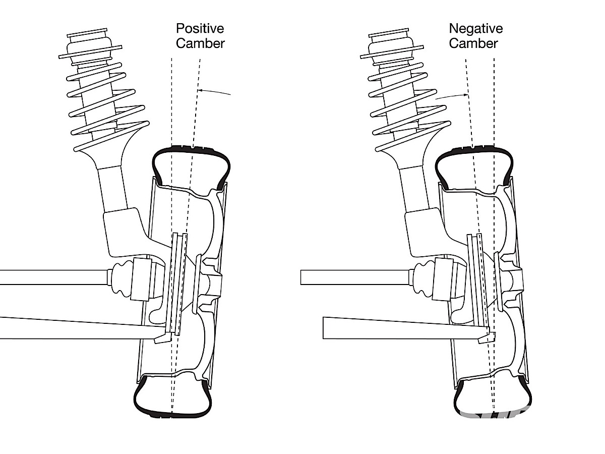
From a performance standpoint, there are a couple of interesting facts to be aware of. If an axle shaft breaks from extreme torque loading, you can expect maximum negative camber immediately resulting, with the tire rubbing on the inner fender well. Vehicle stability will be compromised, but due to its design, there will be no rear steer to send you off the road. Those who have experienced the loss of a trailing arm bushing or complete loss of toe shims in a C2 or C3 know the feeling of rear steer. The rear steers left or right on the throttle, and it steers the opposite direction off the throttle. On a rough road, it may require a stop at the closest bathroom for a change of underwear. The axle shaft universal joints are also an integral part of the suspension camber control. They not only handle driveline torque; they must also withstand vehicle weight. They are not supporting the entire 3500 pounds of the car; as the suspension oscillates over pavement changes, universal joint load also changes.

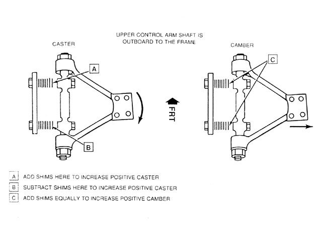
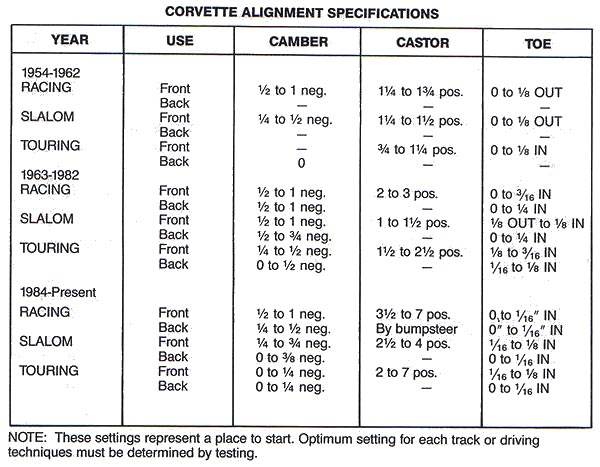
With the differential being the center pivot point for the rear wheels, wear does occur to the differential pinion shaft inside the differential. Changing the differential fluid on a regular basis keeps the inherent metal coursing through the fluid from exacerbating wear, slowing down the inevitable pinion shaft wear. The 1984-1985 front suspension alignment specifications were similar to the C2-C3 Corvette specs with a minimal three degrees of positive caster. Positive caster is a beautiful thing at high speed, planting more vehicle weight at the front tires. By 1986 positive caster was increased to six degrees and has been there since.

1984-1987 upper control arms must be used with 1984-1987 spindle knuckles. GM changed the design three times in that time period. 1984 spindle knuckles had one year only small width caliper mounting pads, requiring spindle knuckle replacement for any 1984 brake upgrade. 1984-1987 steering rack and pinion assemblies were narrower with a rubber isolator steering shaft. 1988 Corvettes have reinforced shock absorber mounting points on the lower control arms, making them a better choice for coilover shock installations. 1988-1996 spindle knuckles are taller, which changes the suspension geometry in a positive manner as the suspension travels through its upper and lower limits.

The C4 Corvette received aluminum suspension components for the first time. Rubber replacement bushings are not available. However, Corvette Central offers rear suspension spindle rods and urethane bushings. Almost immediately, urethane bushing manufacturers made all of the bushings available as a kit. GM offered replacement front and rear control arms with OE rubber bushings, but these have been discontinued. Like the previous generations, C4 Corvettes require bushing replacement. The original rubber bushings have been quite durable. This might be due to the fact that many C4s were driven on a regular basis. According to several prominent rubber component manufacturers, everyday use is always superior to long term storage.

As it turns out, the compounds that help preserve the rubber become active as the rubber is worked through its range of motion. For example, tires flex as they spin. This works the compounds through the rubber and slows down the drying out process. Ultimately, you will need to change the rubber bushings in your C4 sooner than later. The rear camber strut rod bushings wear the most due to their thin strip of rubber that wraps around the inner sleeve. The rear spindle rods are next, usually cracking up and becoming loose in the sleeves. By far the front upper and lower control arms last the longest. When it comes time to service the bushings, there are a few choices. Corvette Central offers new upper and lower control arms with urethane bushings installed. They also have complete urethane bushing kits to replace every bushing, front and rear.
Before searching for the correct bushings, some facts should be known. Rubber bushings are quiet, ride easier and have a shorter life span than urethane bushings. Rubber bushings are vulcanized to the inner and outer sleeves; as they twist, they shear, which works the compounds to the surface and preserves the rubber. This is why the rubber bushed suspension components should never torqued until the vehicle is at ride height. Torqueing the inner sleeve at the lowest point of suspension travel requires the rubber to be sheared past its design limits.

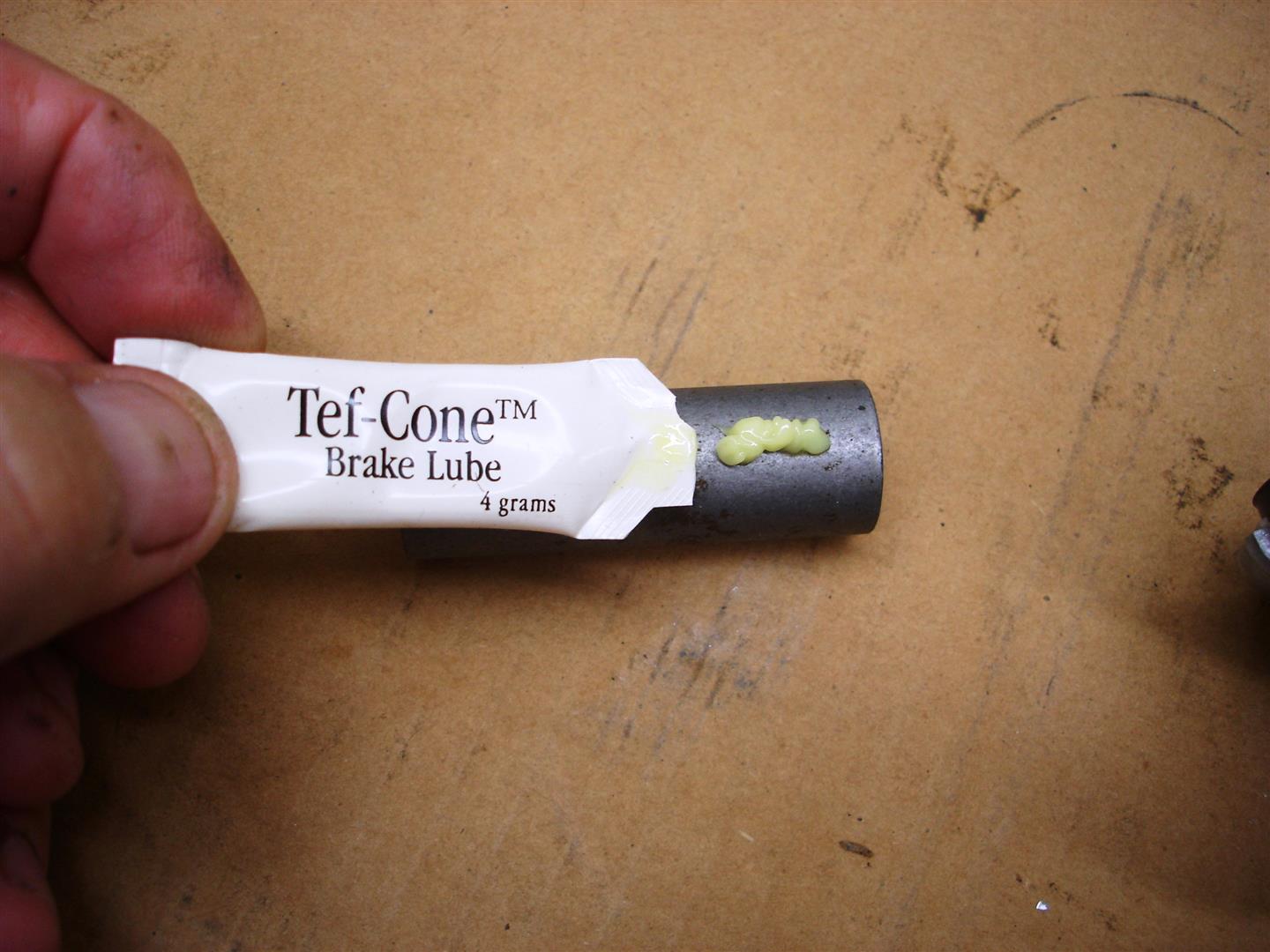
Urethane is currently the best choice. Urethane bushings have positive and negative attributes. Noise is one downside; rough ride can be another. Well lubed urethane bushings will end up being noisy usually dependent on weather conditions (colder wet days seem to aggravate them). The noise does abate on warm summer days. On the plus side they last longer and are easier to install once the rubber bushings are removed. They wear as they rotate on the inner sleeve. When installed correctly, urethane bushings allow unimpeded suspension travel. Chances are the typical Corvette owner may never need to change urethane bushings.

That brings us to the replacement of the bushings and disassembly of the suspension.

Front Suspension Disassembly


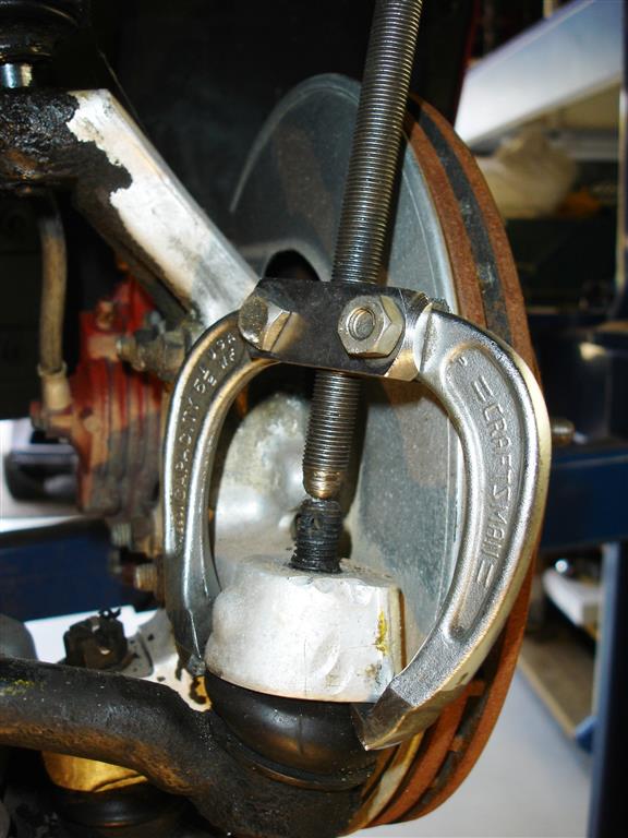
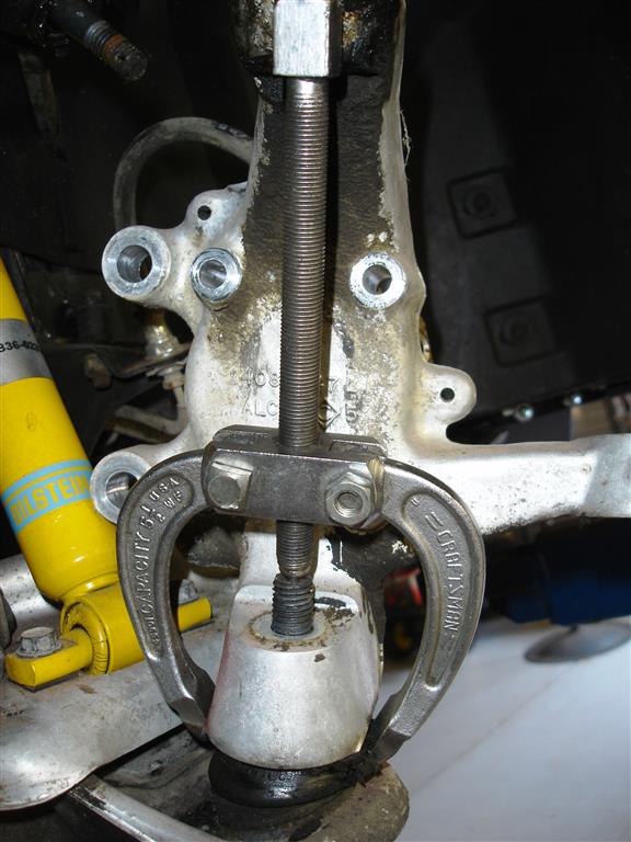
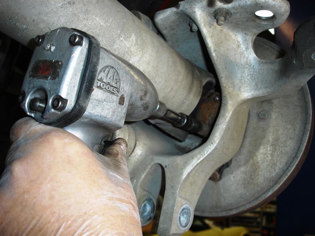
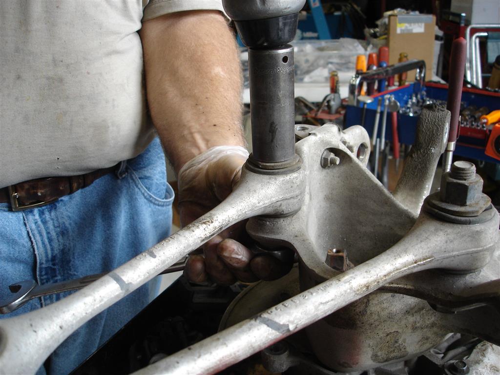
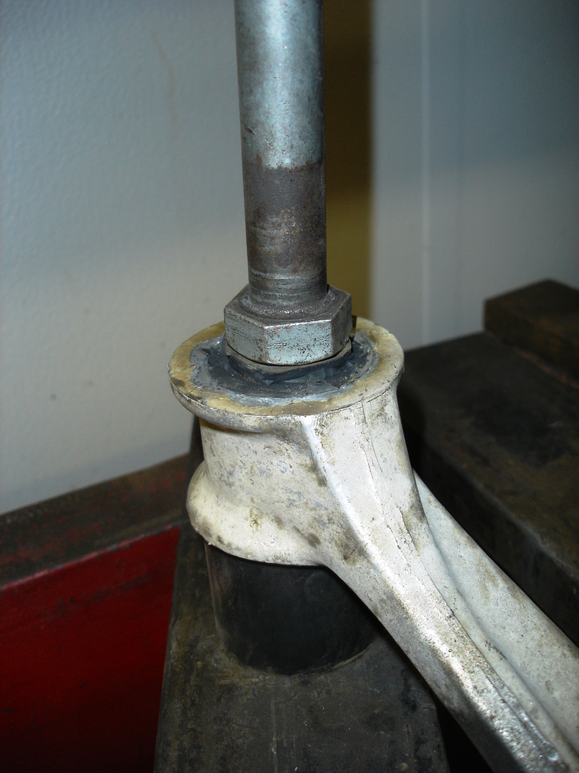
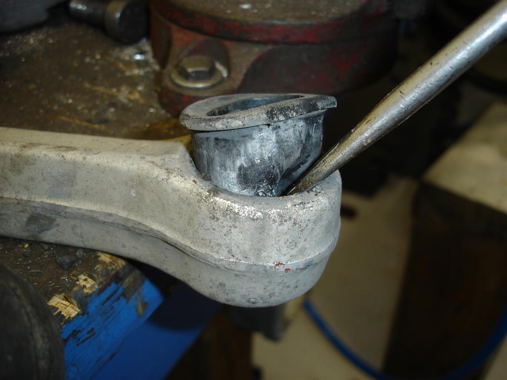
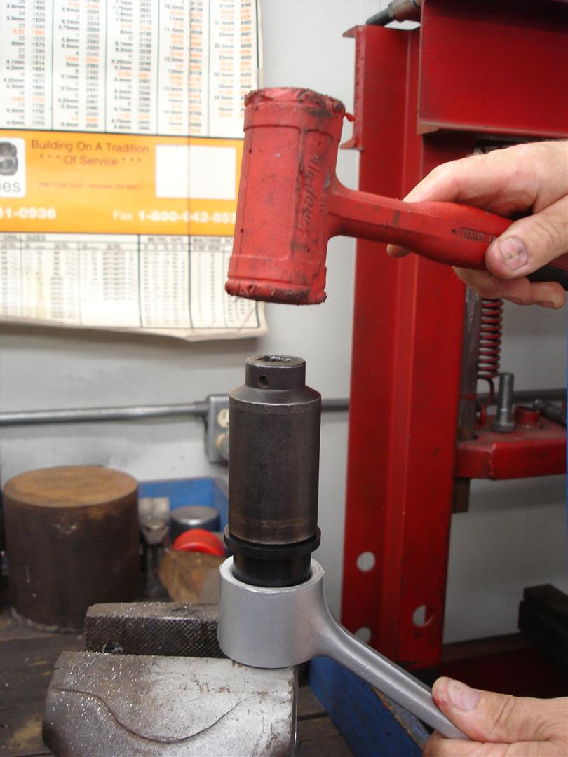
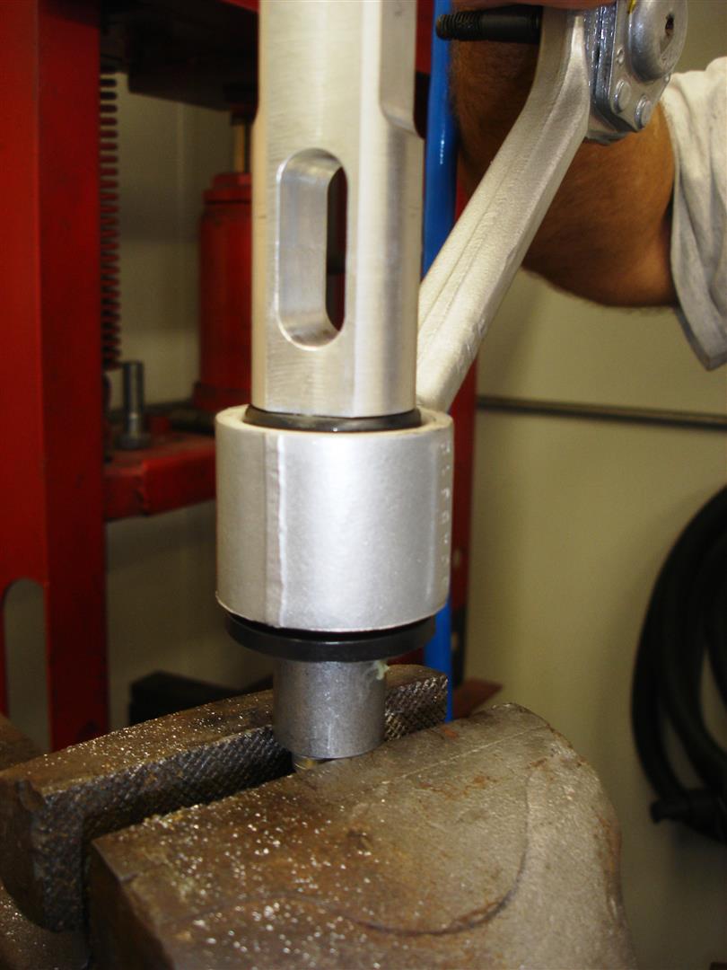
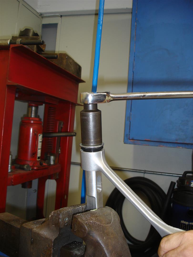
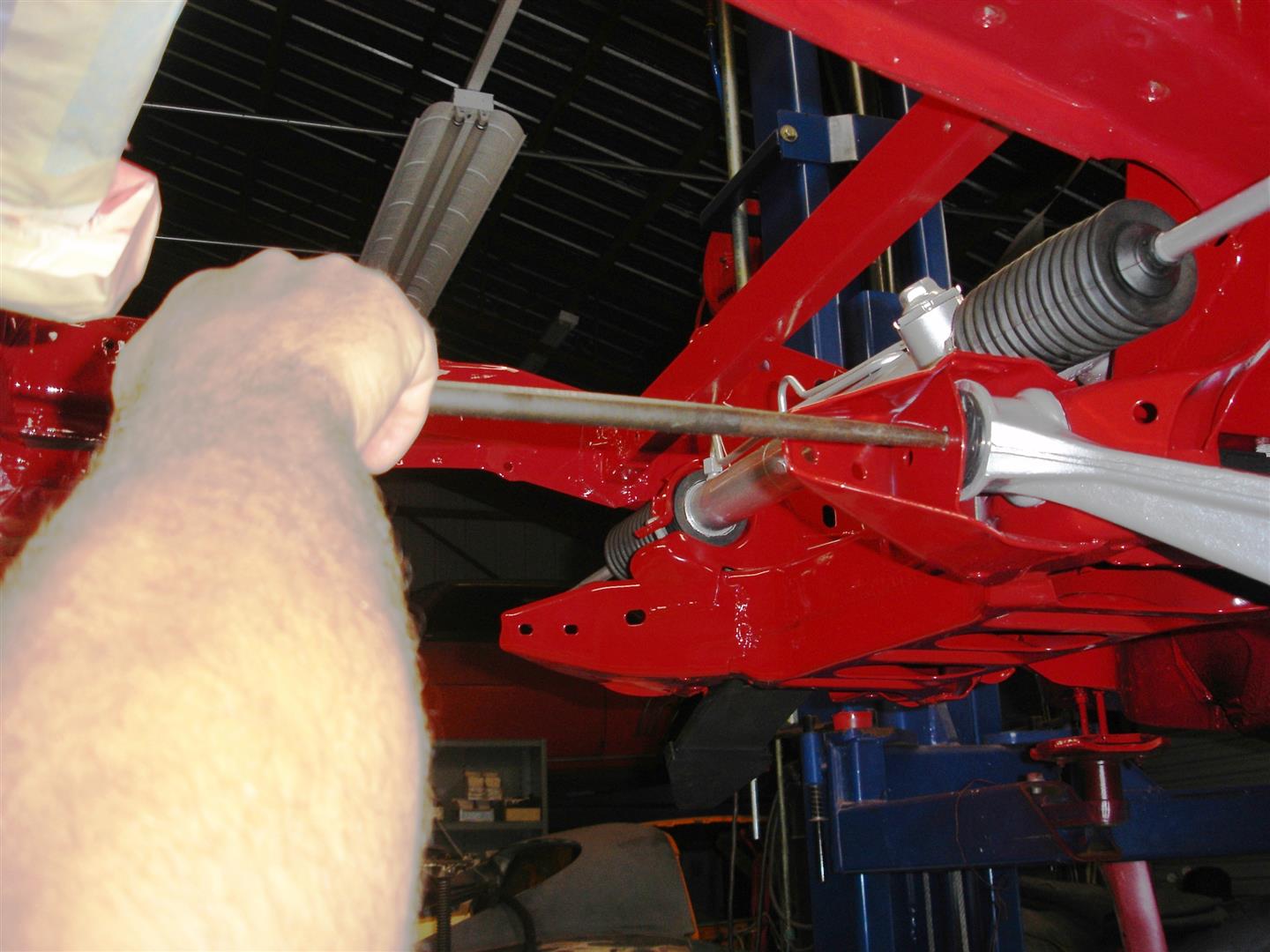
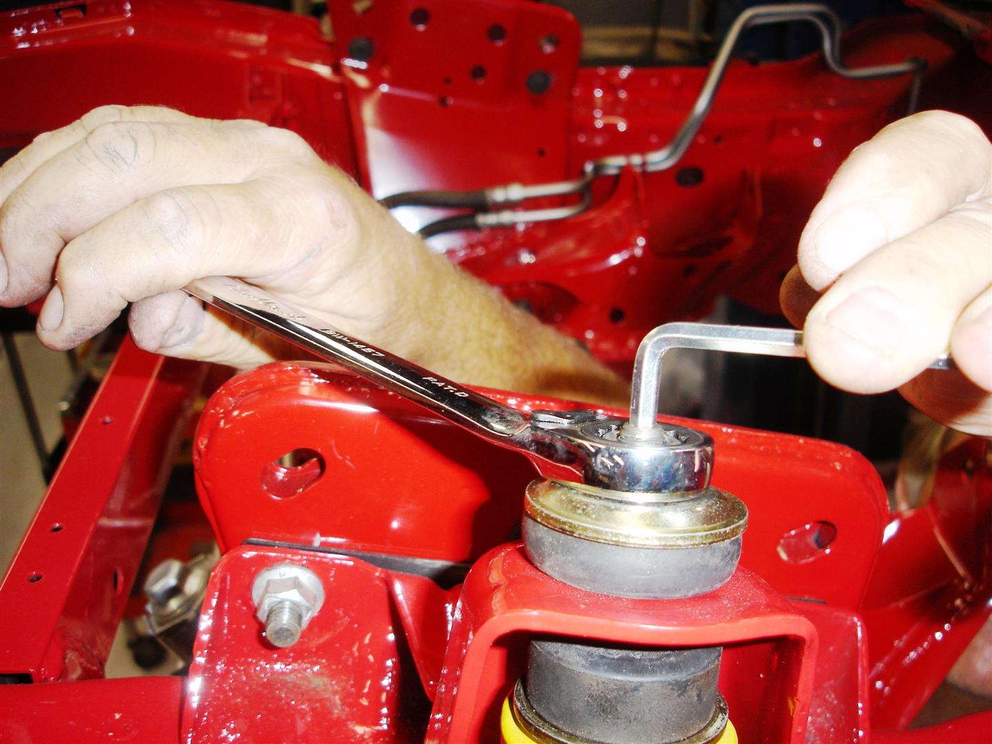
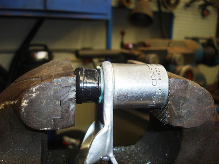
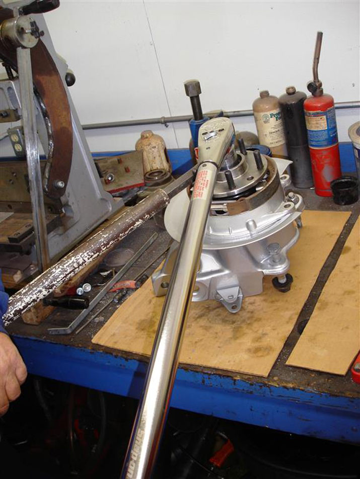
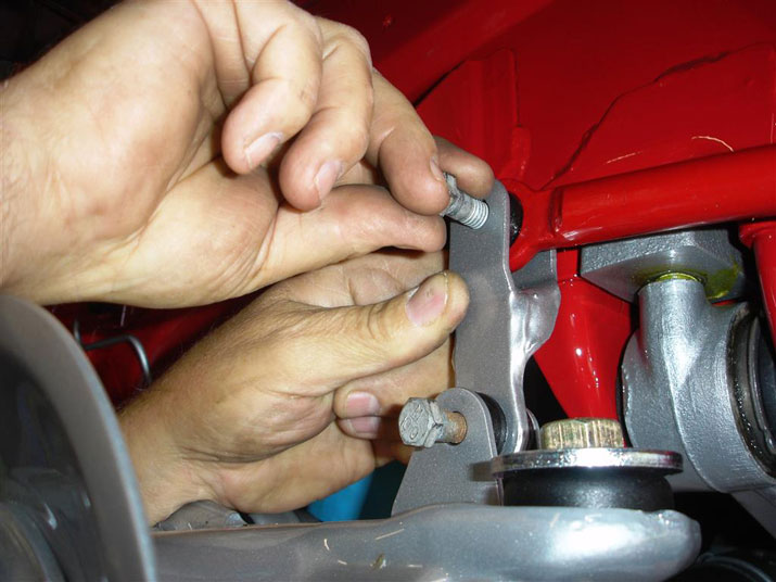
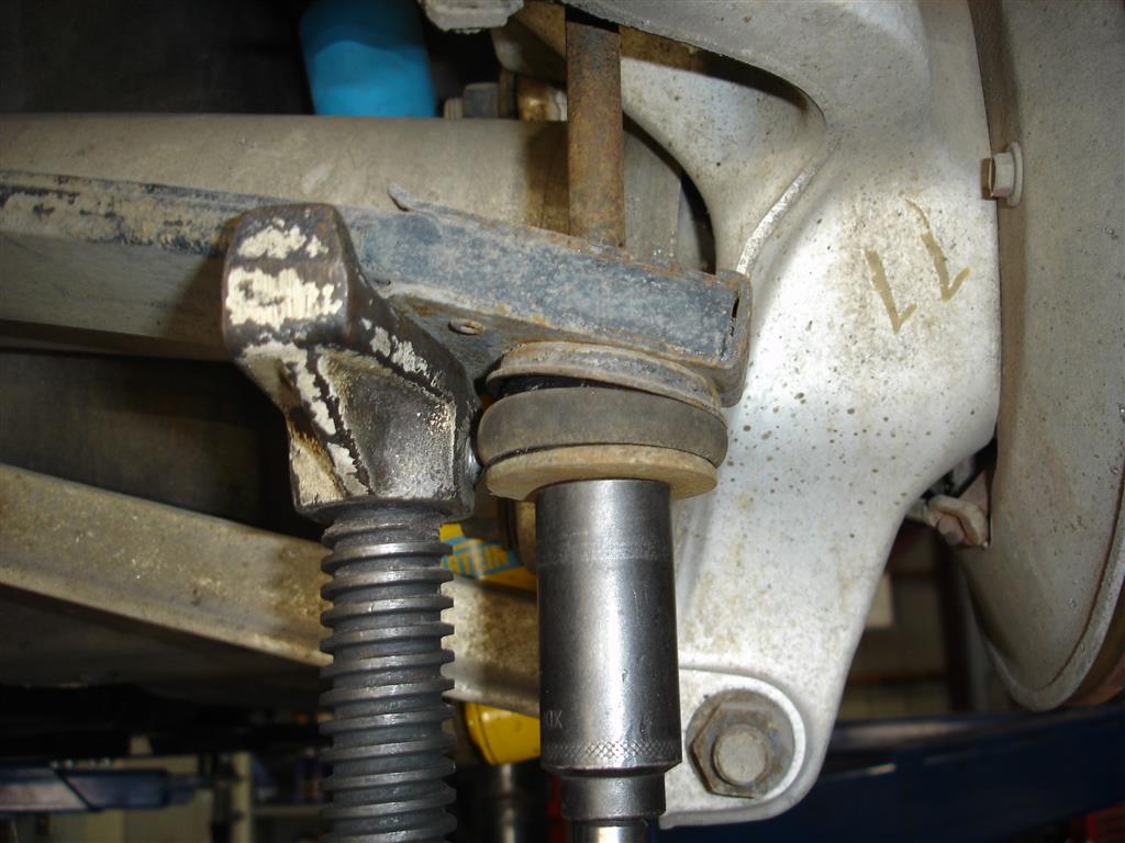
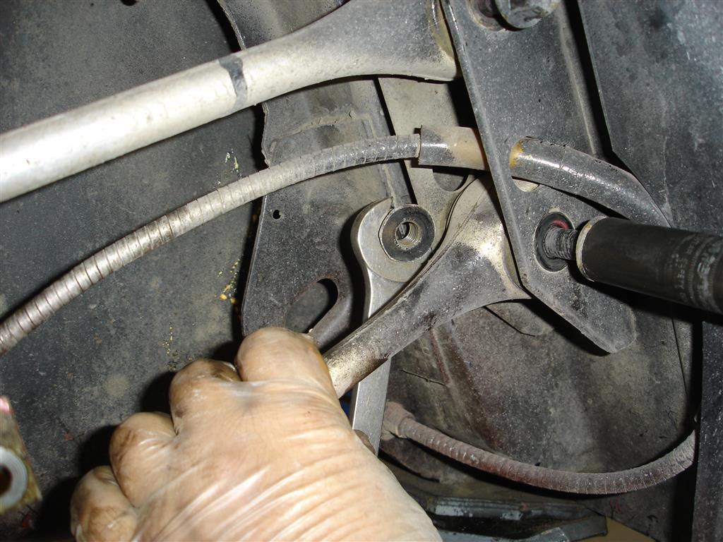
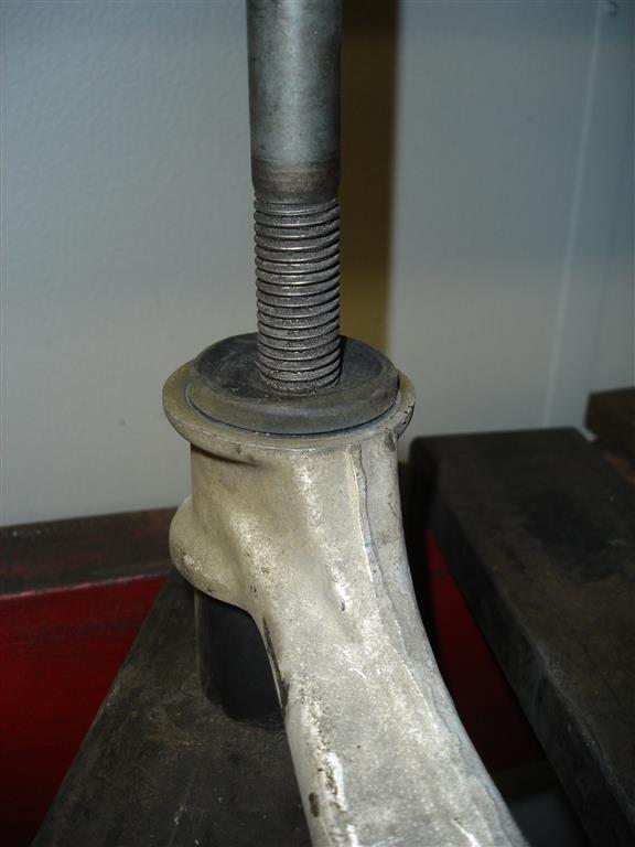
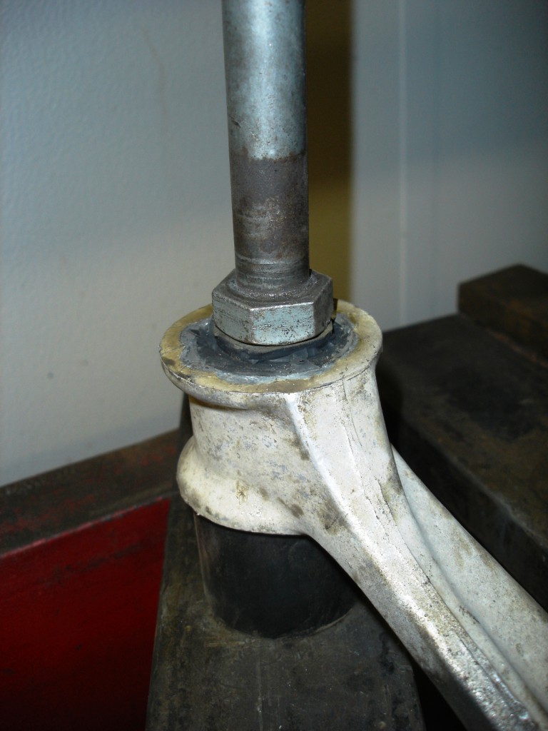
There are a couple ways to dislodge the tapered stud from the spindle knuckle. Some use big hammers to shock the stud loose. Others use pickle forks to force them between the tie rod end and knuckle. The downside is the boot will be damaged if you plan on reusing it. Additionally the metal gets gouged. I prefer to use this simple Craftsman two jaw puller to force the stud out. I use this tool when removing all tapered suspension studs to avoid beating up the aluminum. The same tool works with the earlier iron pieces, although many times it requires a whack on the top of the forcing screw with a hammer after tightening the screw. I remove the tie rod end first to allow the spindle knuckle to easily move around during disassembly.


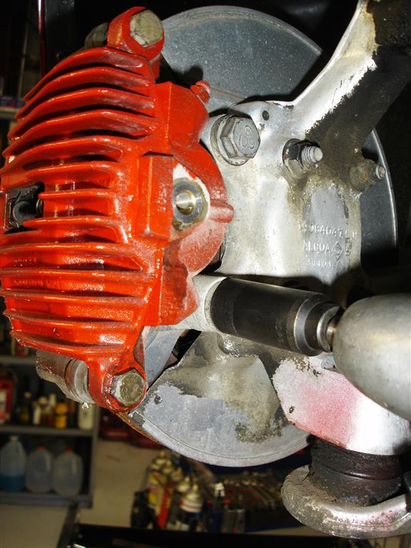
The caliper can be removed from the spindle knuckle mount next. If you plan on servicing the wheel bearings , removing the brake hose is a good idea. Avoid hanging the brake caliper from the hose. If you have 100K miles or more on your C4, now is the time to replace the hoses. Corvette Central has stainless steel braided hoses available which alleviate the possibility of ballooning hoses and spongy pedals.


Sway or anti-roll bar removal is next with a 15mm socket and wrench to hold the nut. The entire suspension uses metric fasteners. Be careful that the wrenches fit the fasteners tightly. These are very good fasteners with built-in washers, so try to avoid losing them and place them in specific areas to remember what went where.


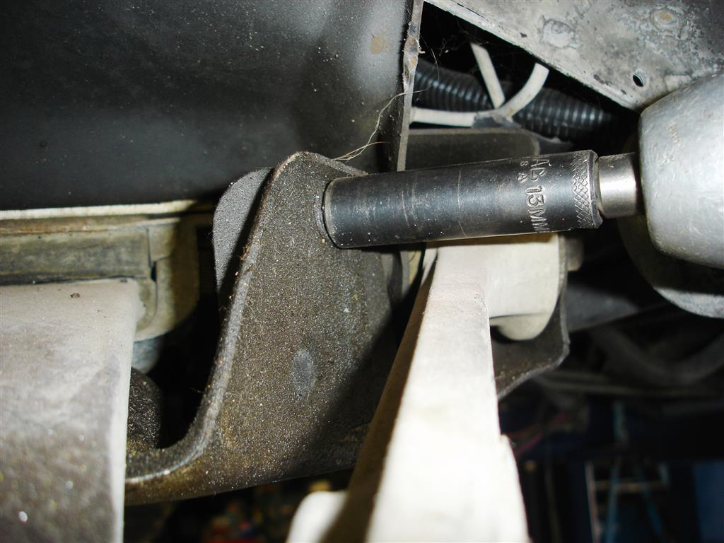
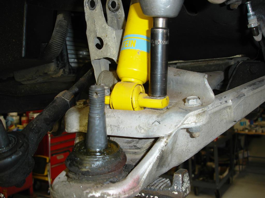
Early C4s have these transverse spring travel limiters. If you plan on removing the front spring, remove them now. There are two 13mm screws on the sides and two on the bottom. If you forget to remove them, the spring must be unloaded if the lower control arms have been removed. The best policy is to remove them first.


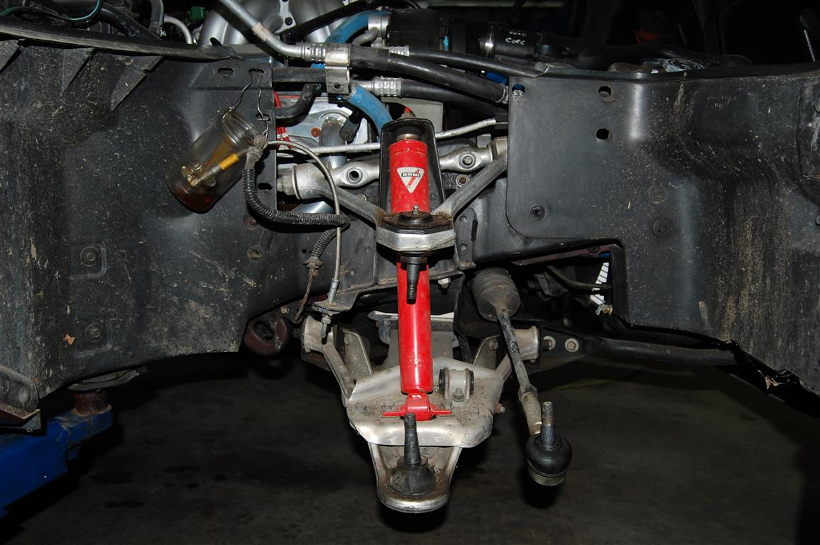
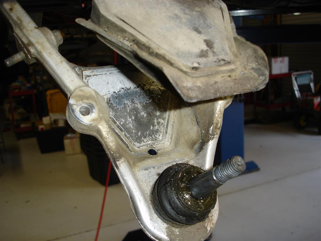
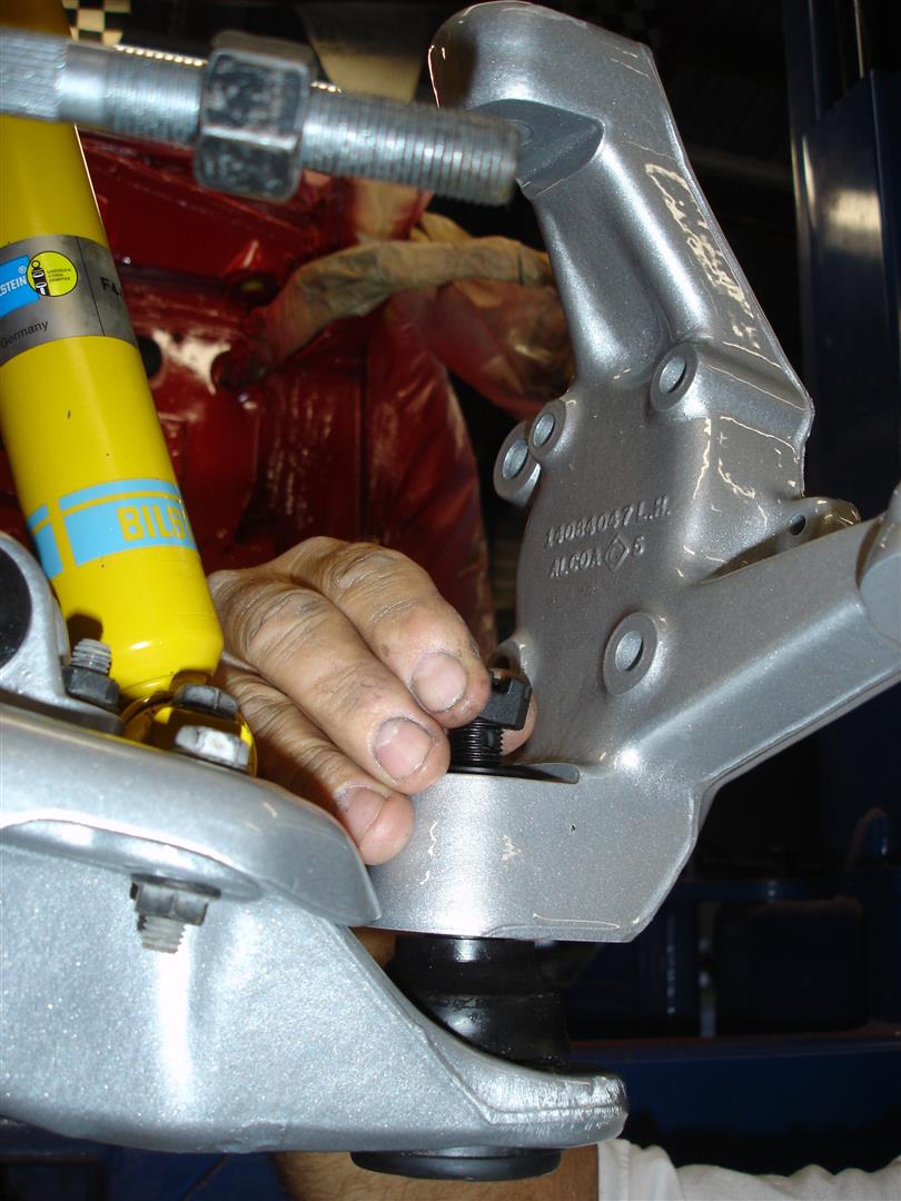
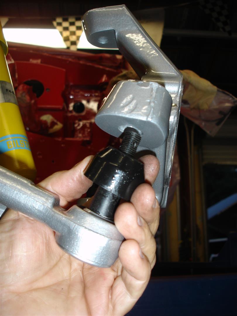
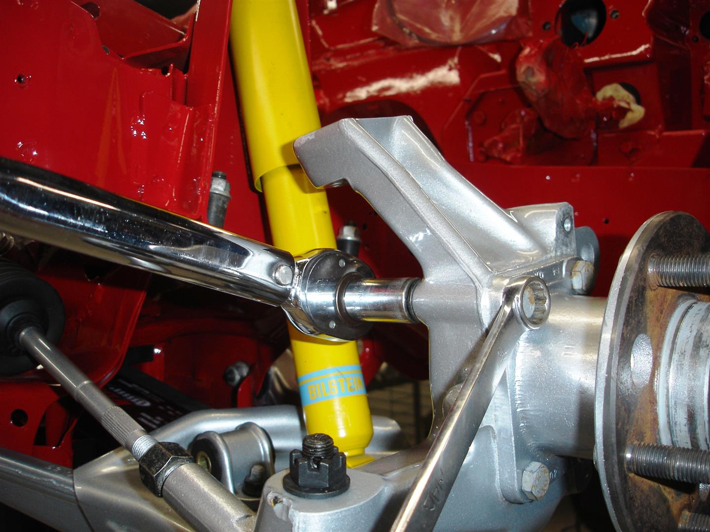
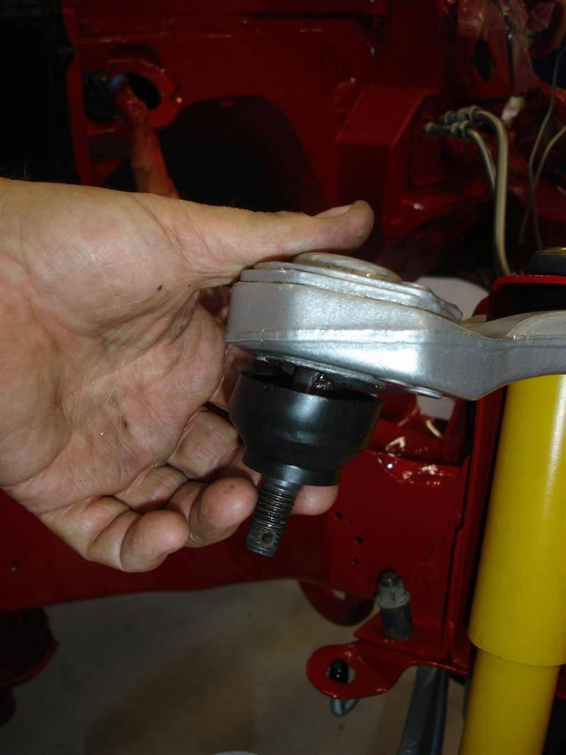
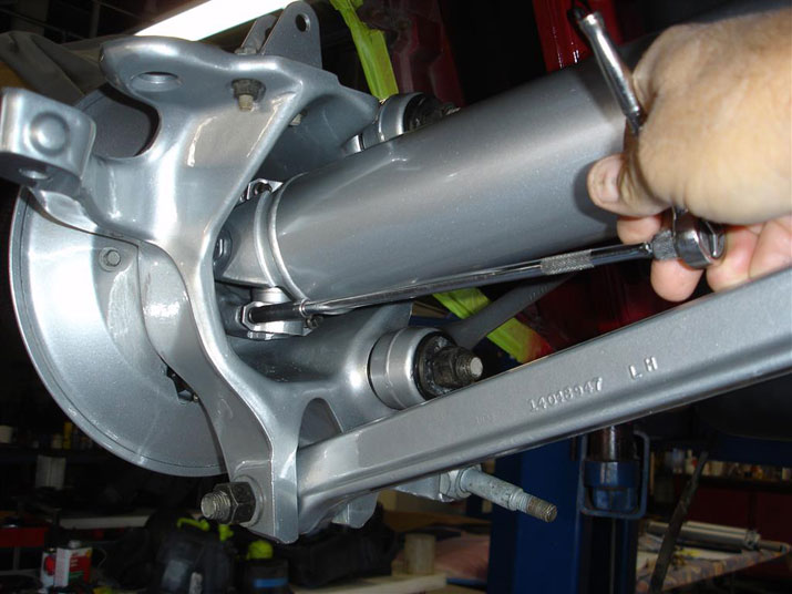
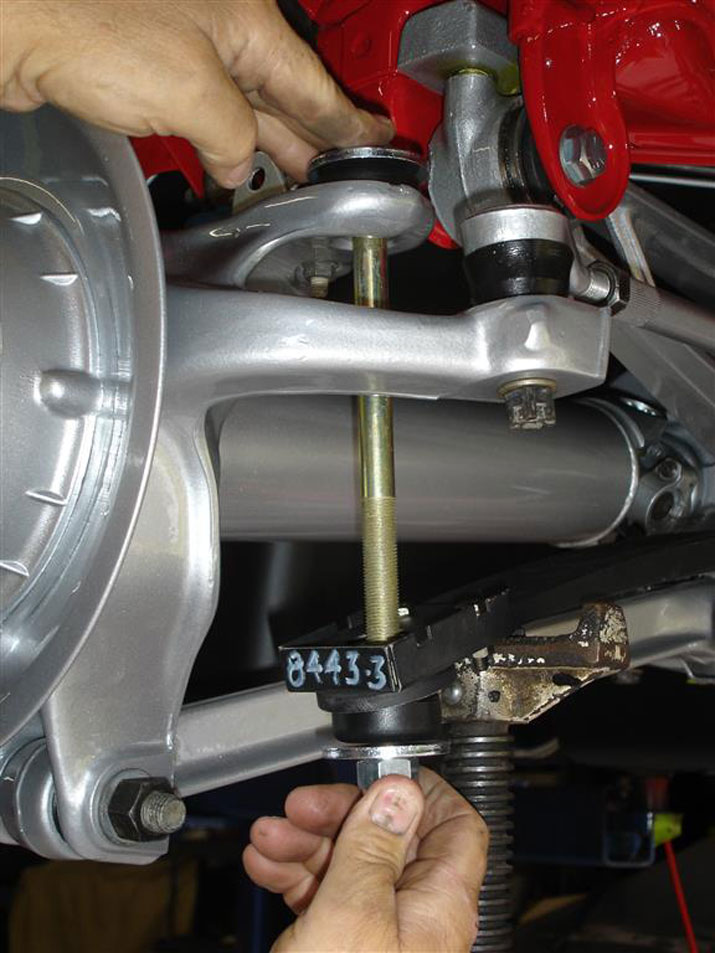
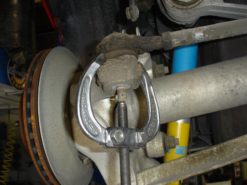
The ball joint studs are removed with the same puller. The knuckle can be removed from the ball joints as long as the shock absorbers are not removed or loosened. There will be slight tension on the studs making the removal process easier. This early C4 is getting a full suspension restoration, so as you can see, the wheel bearings were removed for easier knuckle removal. Many times the studs are not very tight in the aluminum, making this an easy task with the puller.


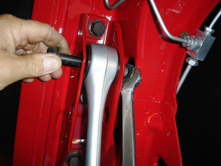
Now the upper control arms can be removed with an 18mm deep socket. The control arm bolts have flats on the inside to keep them from spinning during removal; try to keep pressure on the socket at all times if you use air tools for removal. The hammering action of the impact will beat up the frame area where the bolts sit. Note the position of the spacers and shims between the upper control arm shafts and the frame. All C4 Corvettes have short and long spacers to set the initial caster; 1984-1985 Corvettes will have long spacers at the rear (closer to the firewall) with short spacers at the front. 1986-1996 cars have the spacers reversed: short at the rear and long up front for increased caster. In the shop, we set all C4s up with the long spacer up front, short at the rear. The best policy is to record where the shims where and place them in the same position. Once the suspension service is completed, all C4s receive the same suspension alignment set-up specifications. The immediate result is a huge smile on the 1984-1985 C4 owners face.


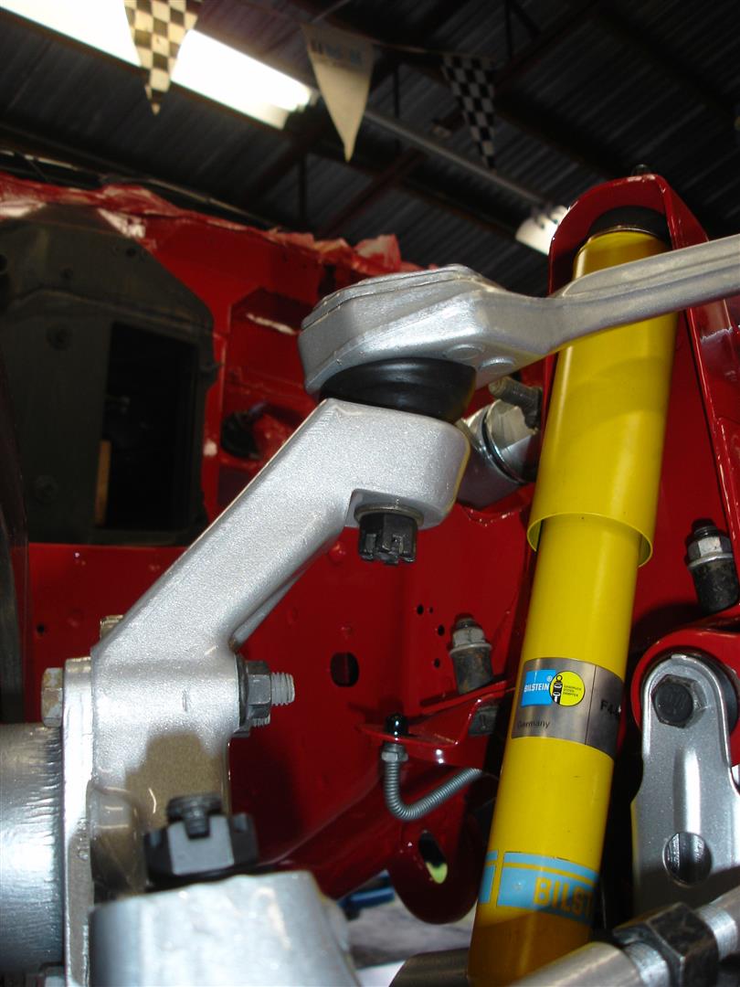
This can be a slight problem, but as you can see, the control arm did come out for service. The bolts must be backed out to get the control arm up and over the shock mount. When it comes time to assemble, make sure that the control arm bolt flats are in the correct position and seated flat against the frame or a sudden change in vehicle control can be experienced.


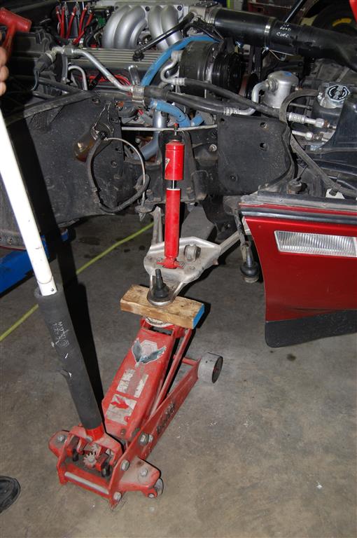
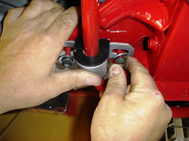
The upper shock mount is removed with the floor jack placed under the lower control arm. Correct jack positioning is essential so it can roll inward as the spring unloads downward. The 2 x 4 block of wood keeps the jack from slipping on the metal surfaces. I remove the lower ball joint grease fitting to allow the wood to sit flat on the ball joint.


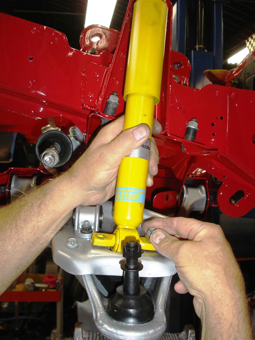
Shock removal is next. This 1986 has the old style plate to mount the shock and anti-roll bar. I remove this mounting plate on the 1984-1987 C4s to make lower control arm removal easier. 1988-1996 cars have the shock mount cast into the lower control arm.


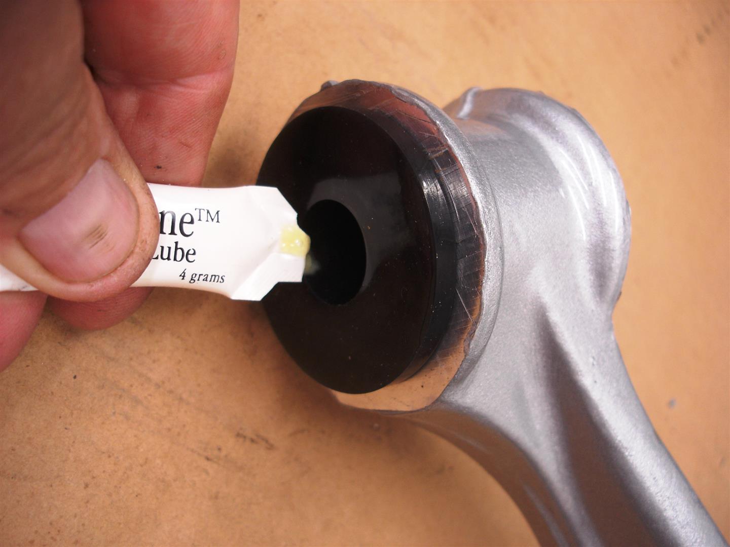
The plate is removed and the control arm pushed downward away from the spring. I apply silicone grease to the area in the control arm where the spring sits during assembly.


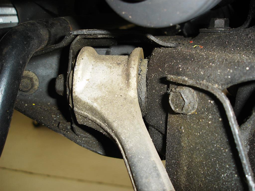
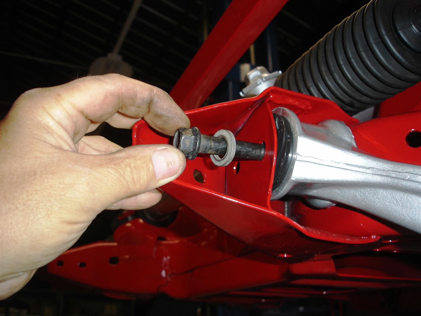
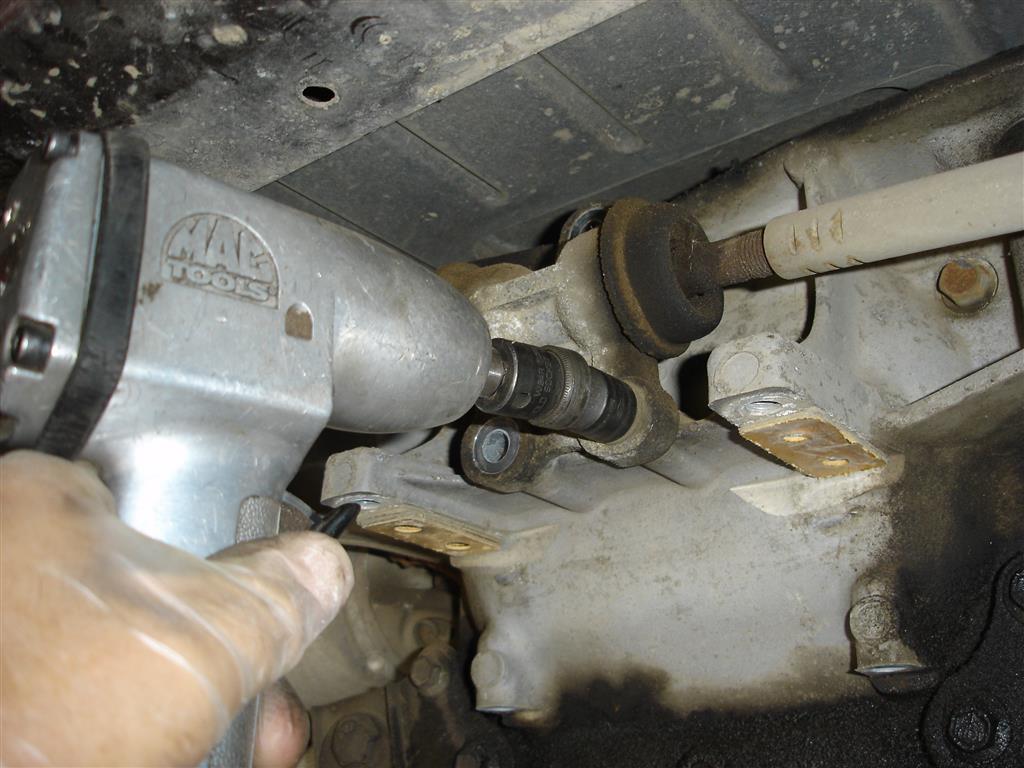
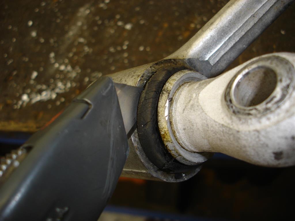
These lower control arm rubber bushings are cracked up and ready for replacement. Removing the lower control arm 15mm pivot bolts can be difficult. Accessing the inner 18mm nut requires a shallow socket. Wrenches will not sit flat and the nuts are really tight. When the time comes for assembly, these bolts must absolutely be torqued to make sure they are tight enough. I often have to tighten them for customers complaining a clunking sound in the front end during braking or over large bumps. Once the front lower control arms are removed we’ll move to the rear.


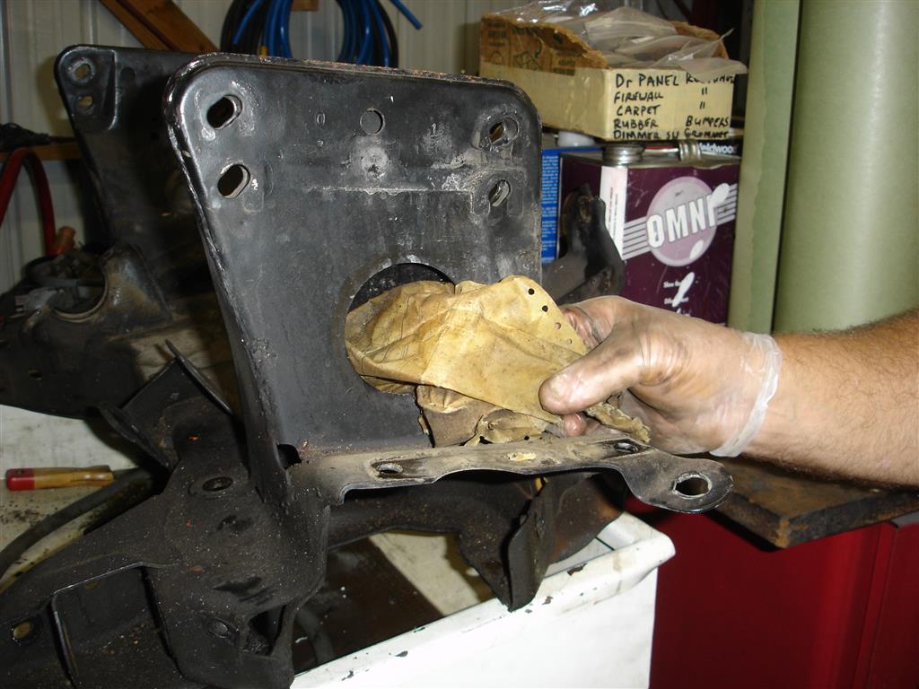
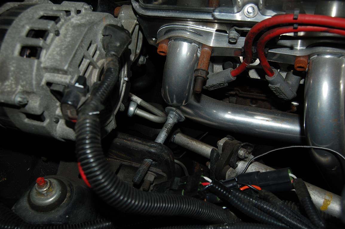
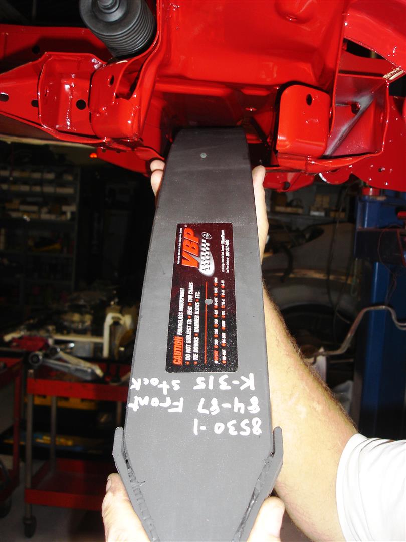
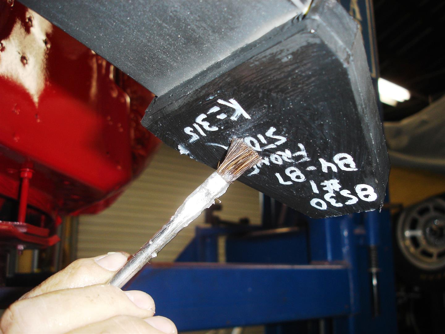
For those of you wondering where GM hid the build sheet, this 1985 sheet was found in the front K-member after removing it from the front frame rails. Removing the K-member is a major task, requiring engine removal holding it off the engine mounts. The brake lines must also be removed.

Rear Suspension Disassembly


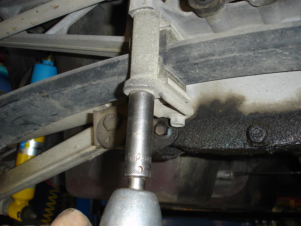
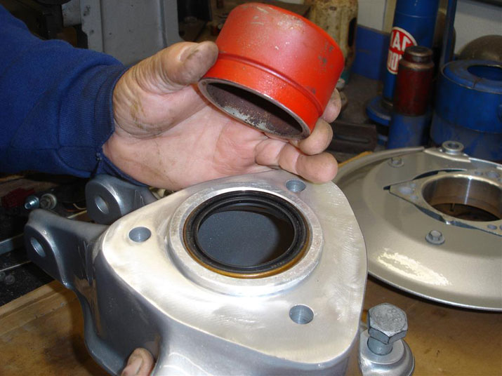
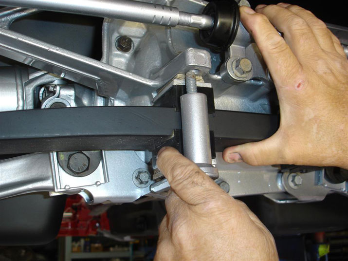
Rear suspension disassembly begins with rear spring unloading. Note the jack is placed on the metal spring end reinforcement. Placing the jack on the fiberglass portion of the spring can damage it and cause failure. Once the 21mm nut is removed, the rubber spring cushion and washer should be removed. I have found the cushion can catch on the bolt and make you think the spring is unloaded. The cushion then pops off under high pressure. Once the spring cushion and washer are off ,the jack is slowly backed off unloading the spring.


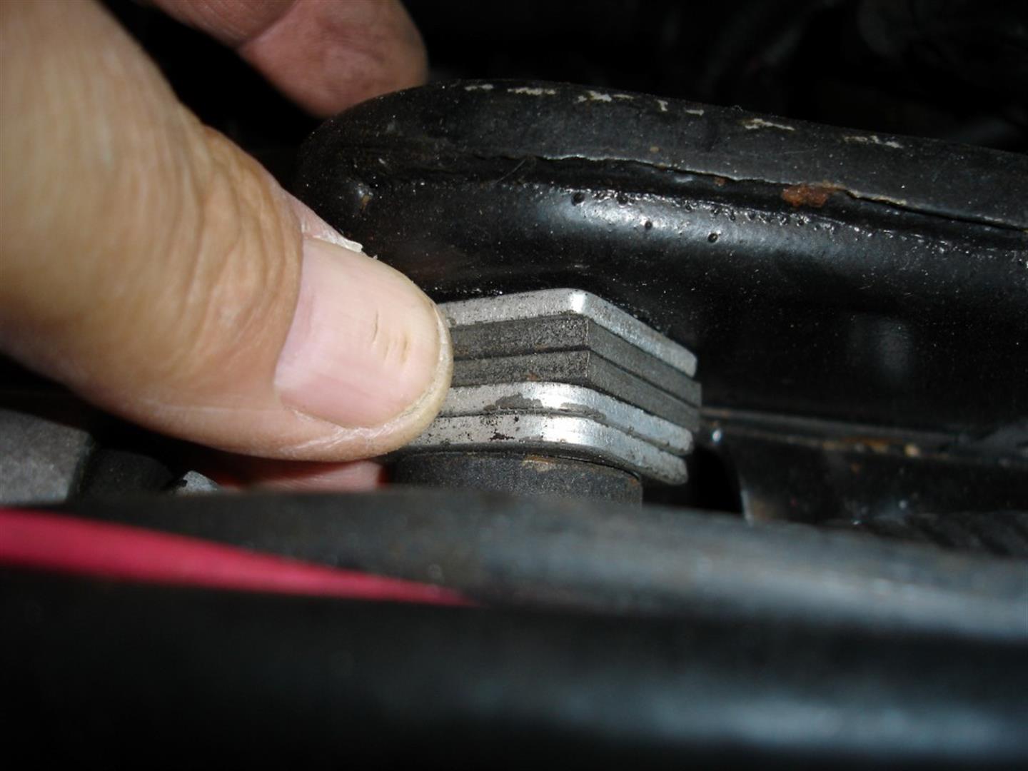
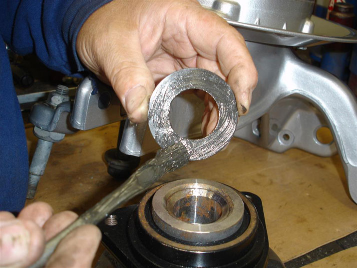
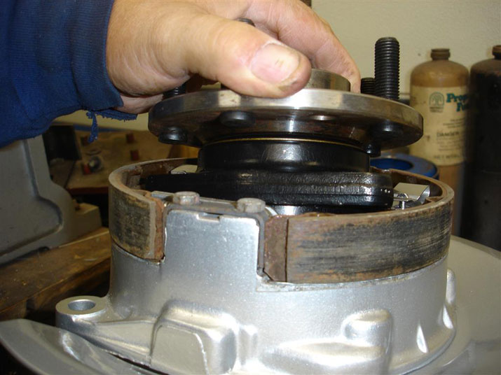
With the spring unloaded at both ends, the spring can be removed from the differential housing. The 15mm bolts are backed off a couple of turns at a time until the retainer is loose from the spring. Removing one bolt at a time completely can snap one or both of the retainers from the spring tension. Note the stack of aluminum and fiber spacers at each retainer for correct reassembly.


The toe link tie-rod ends are removed with the gear puller. Many times, these just pop out after the nuts and washers are removed. A steel washer must be used at each stud to prevent the nut from digging into the aluminum.


If you plan on removing the differential, the toe link can be removed from the differential housing. 15mm screws hold the toe link assembly onto the housing; these do not have to be removed for rear spindle knuckle work. If you replace the toe link or tie-rod ends, measure the overall length of the toe link before disassembling the rod ends. Adjust the new link or rod ends to the same length for the trip to the alignment shop.


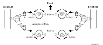
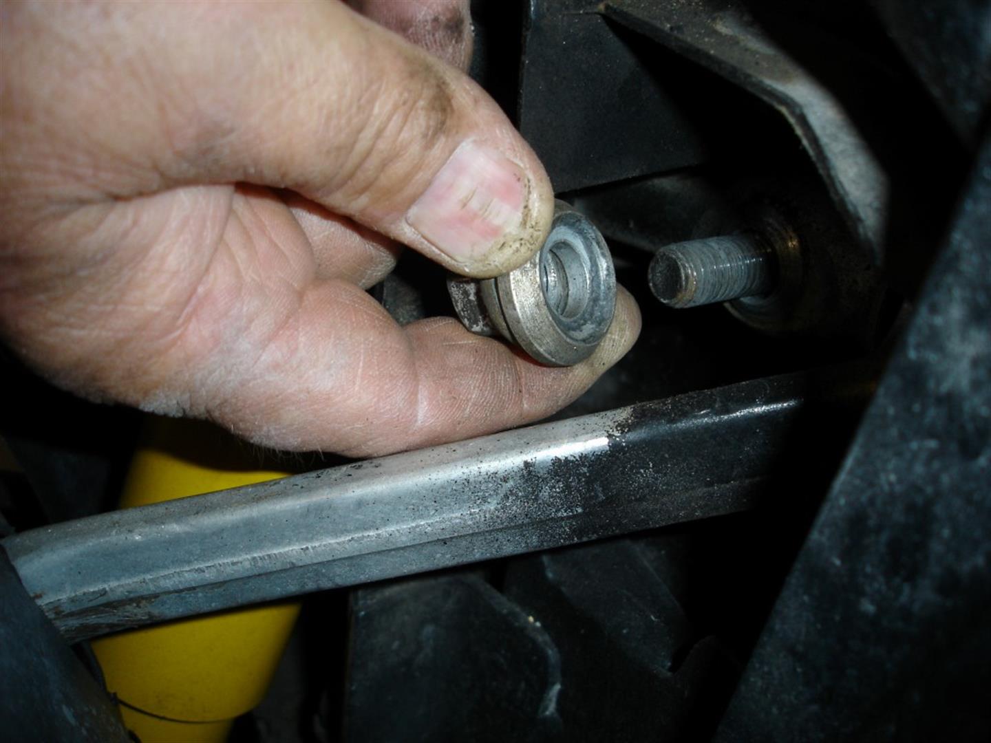
Marking where the rear camber cams are before disassembly will get you close enough for a safe trip to the alignment shop. Remove the 21mm nut while holding the 21mm bolt, then remove the washer and cam bolt.


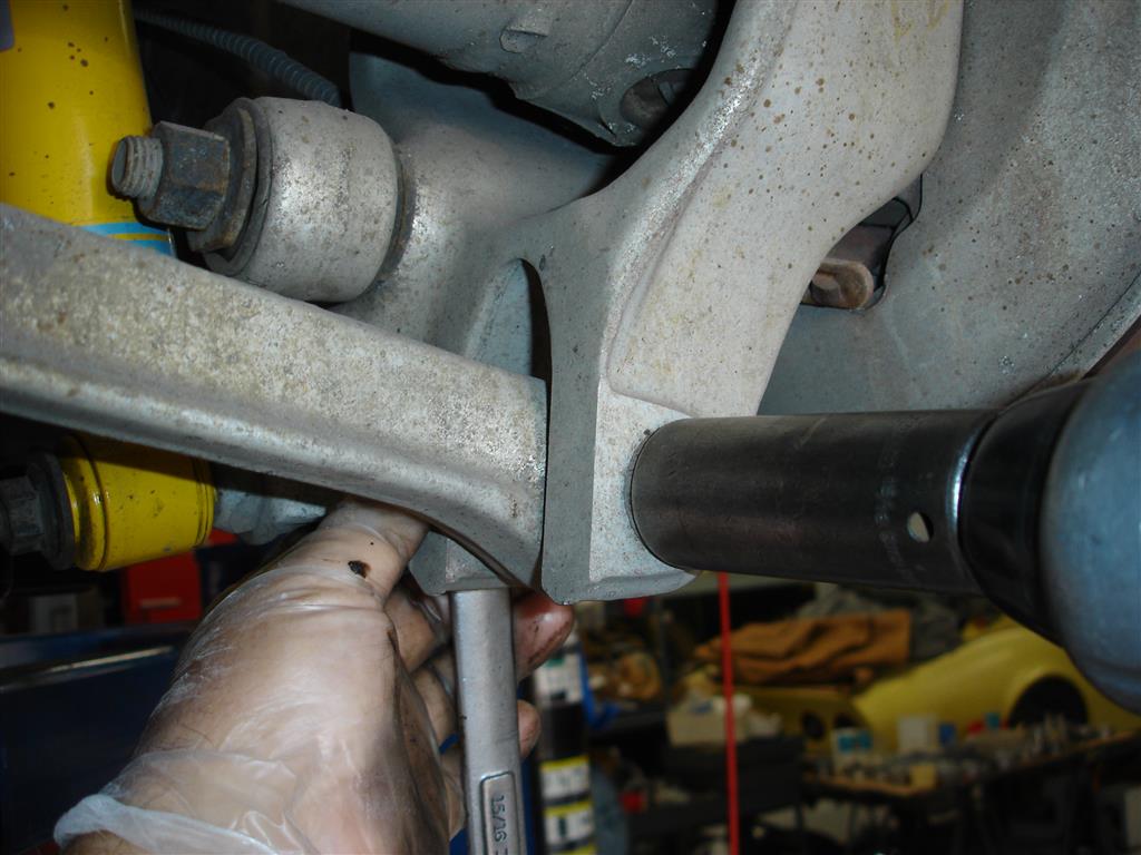
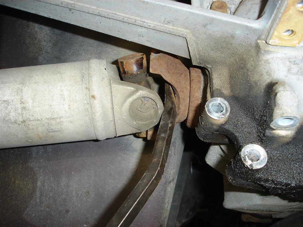
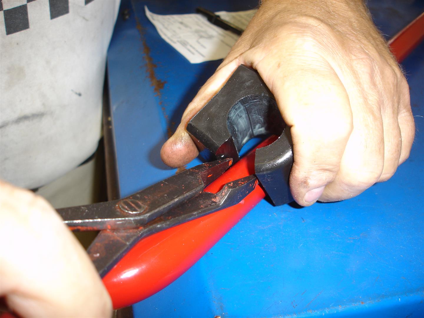
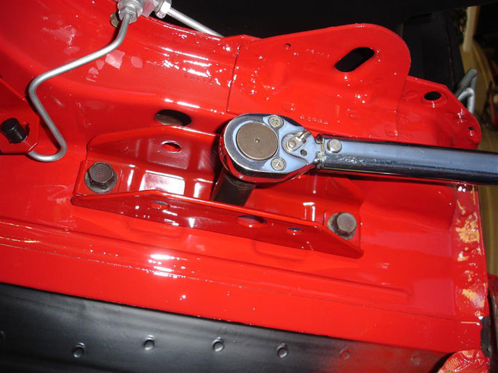
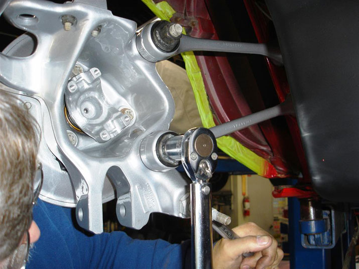
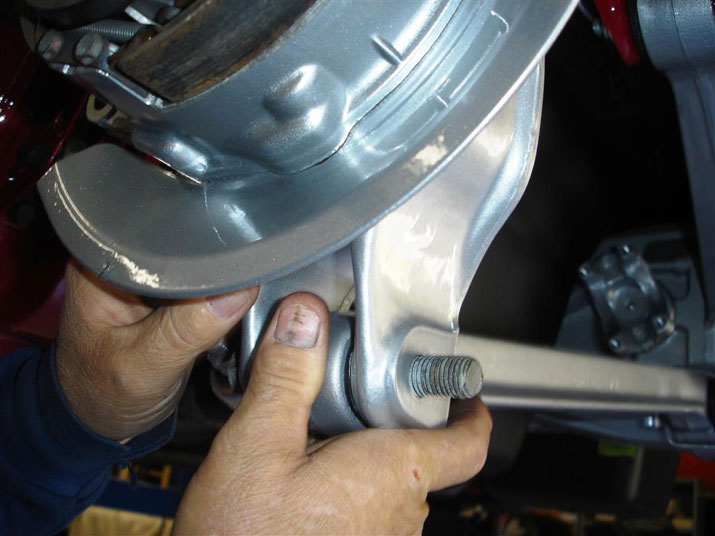
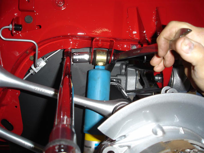
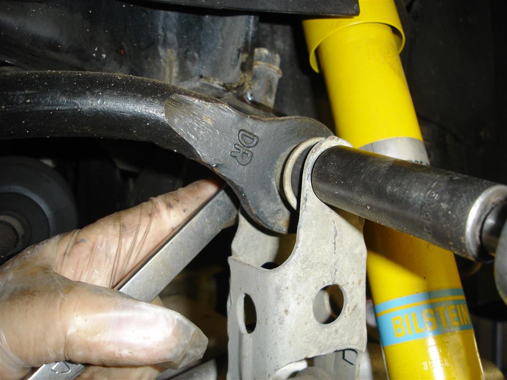
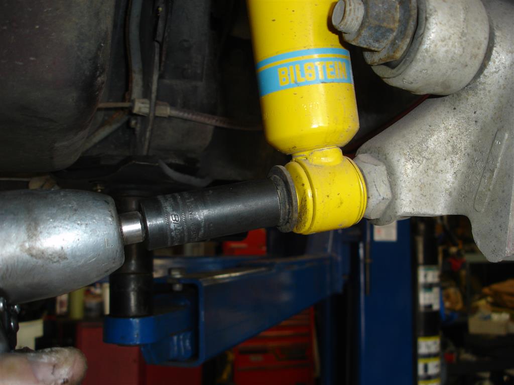
The outer camber strut rod connects to the spindle knuckle with a large bolt and nut; I find that removing the nut is always easier than trying to turn the bolt out of the nut. A 24mm or 15/16 socket fits the large bolt and nut best. There is no need to support the knuckle during the camber strut rod removal.


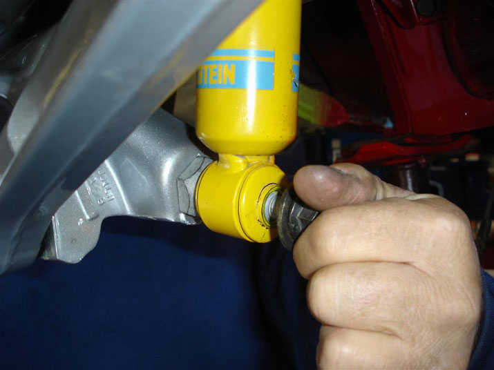
Lower shock mount nut removal requires an 18mm socket. The spindle knuckle will drop down a bit, but will not be a problem with spindle control when the shock is removed from the stud.


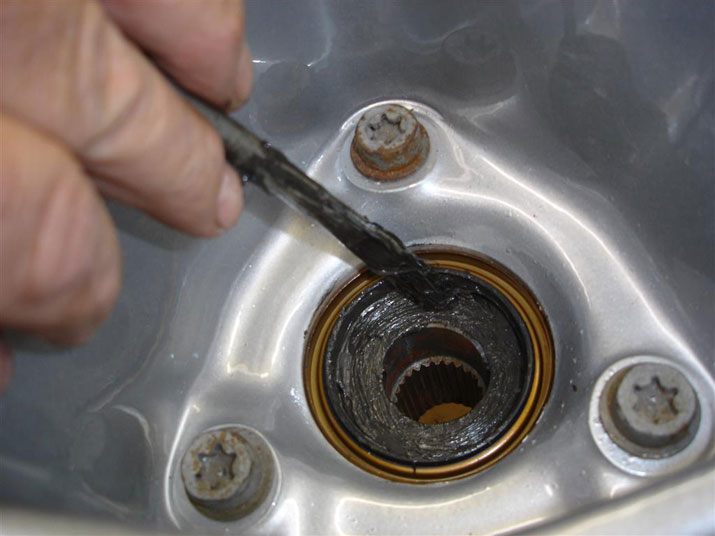
Axle shafts are removed with an 8mm socket; rotate the axle shaft so that two bolts are removed on the inside at the top.


At the outside, the 8mm screws are removed at the bottom side of the axle. Once both sides are done, at the inside top and outside bottom the shafts are rotated 180 degrees. The remaining screws are then removed.


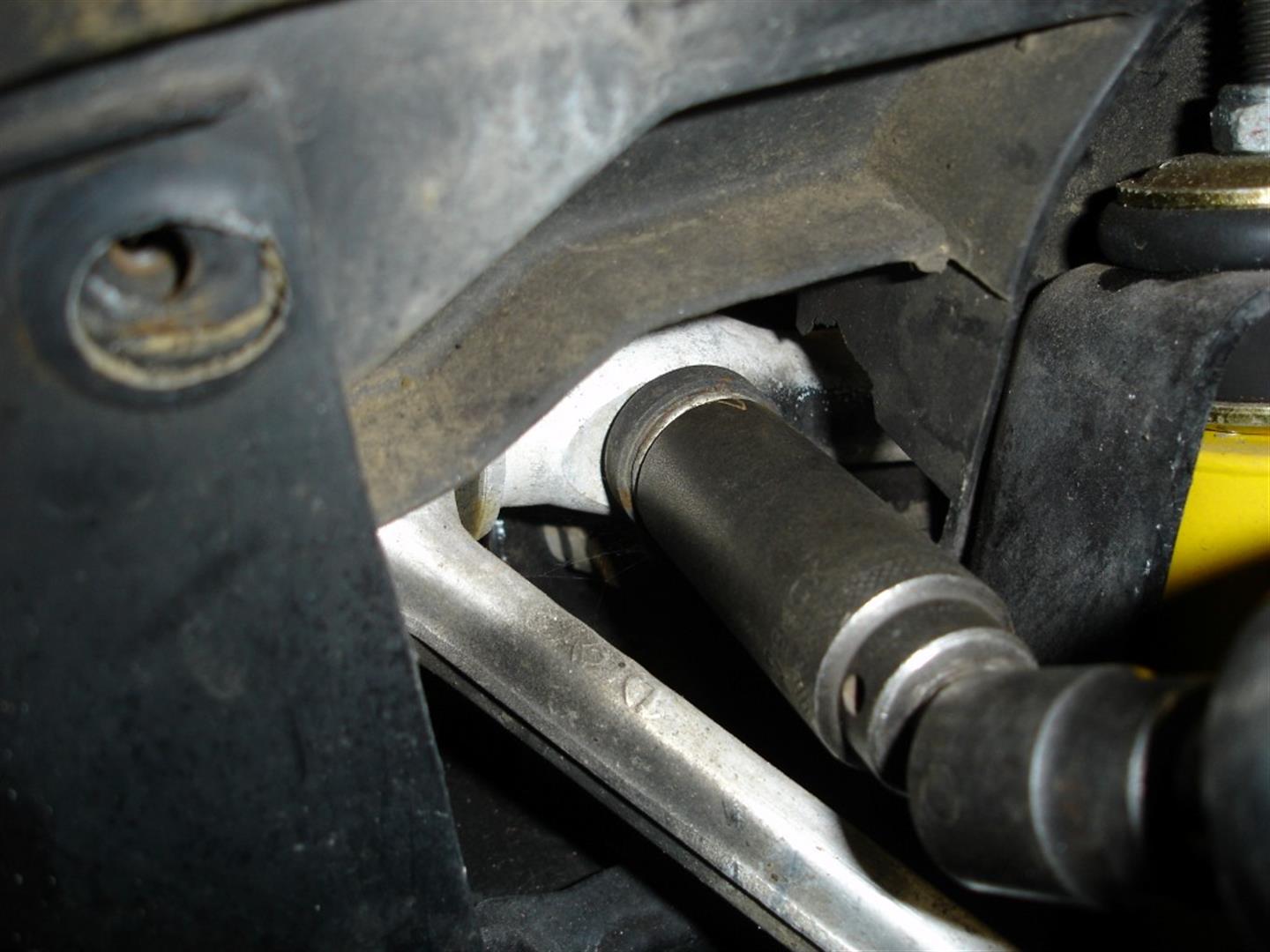
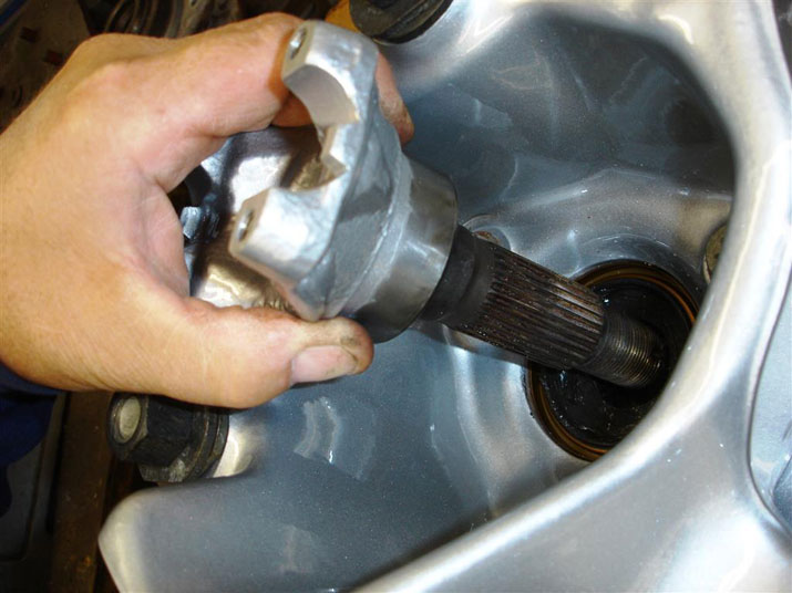
The inner camber mount supports were removed for easier axleshaft access. This differential was leaking before the camber mount supports were removed. Once removed, the leak became quite noticeable. The decision was made to remove the differential for a reseal. A large pry bar is used to pop the universal joints out of the axle shaft yokes. Be careful to pop both cups loose before trying to remove the axleshaft or a universal cup can be dropped and the needle bearings will be all over the floor.


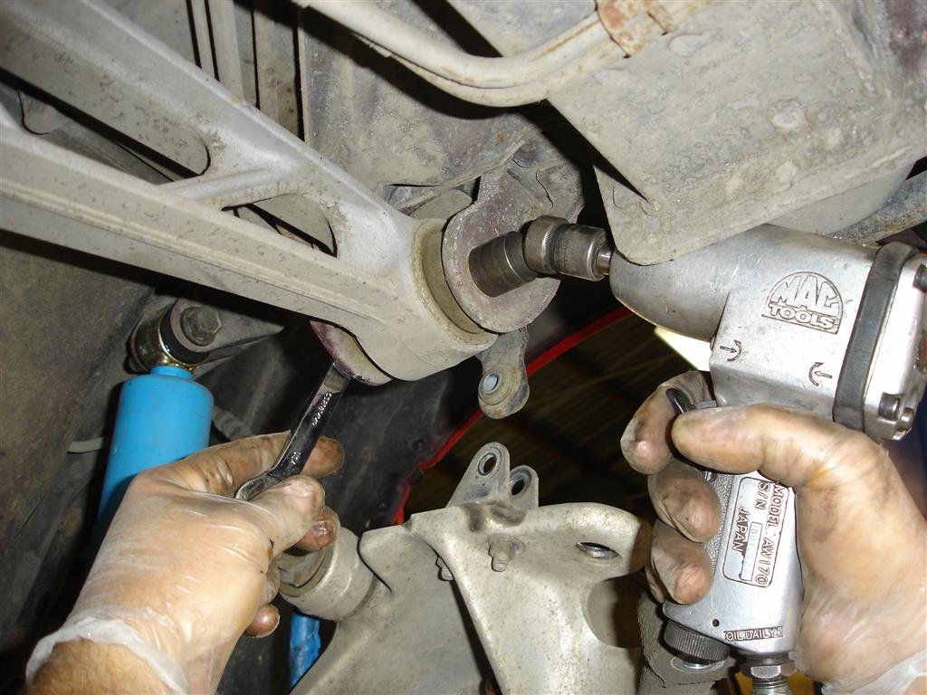
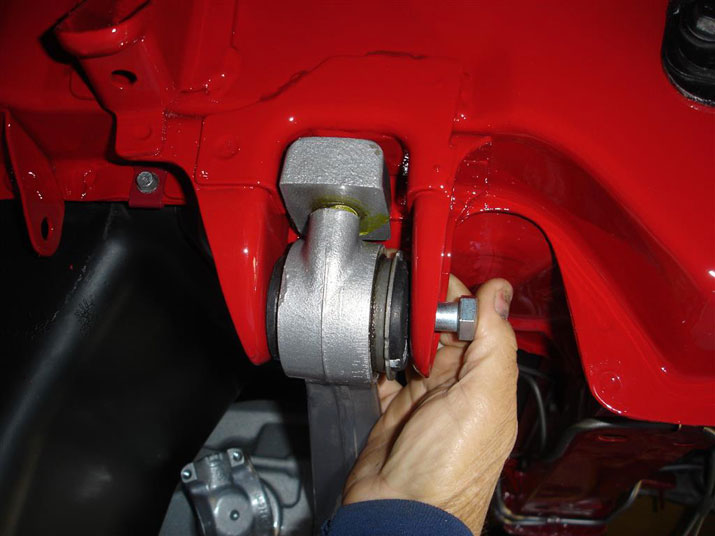
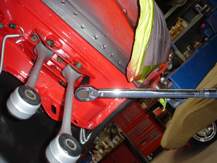
Our project included removing the differential from the chassis for repair of the leak and to replace the cushion supports. An 18mm socket and wrench are used to remove the through bolts holding the differential in place.


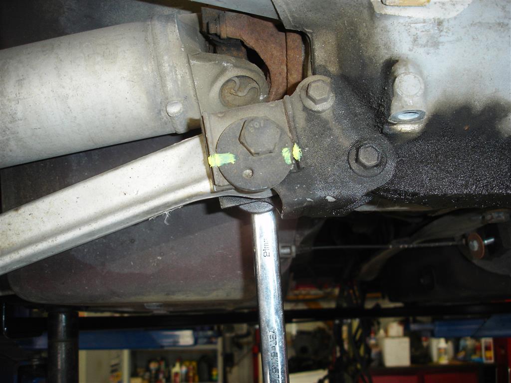
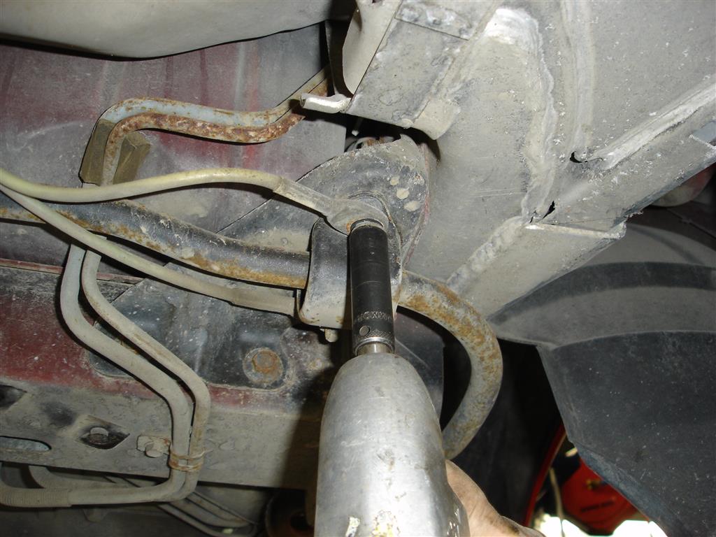
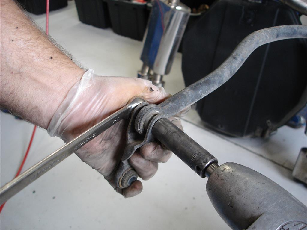
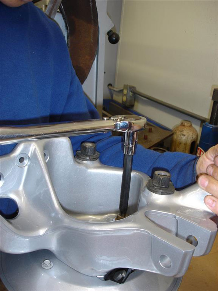
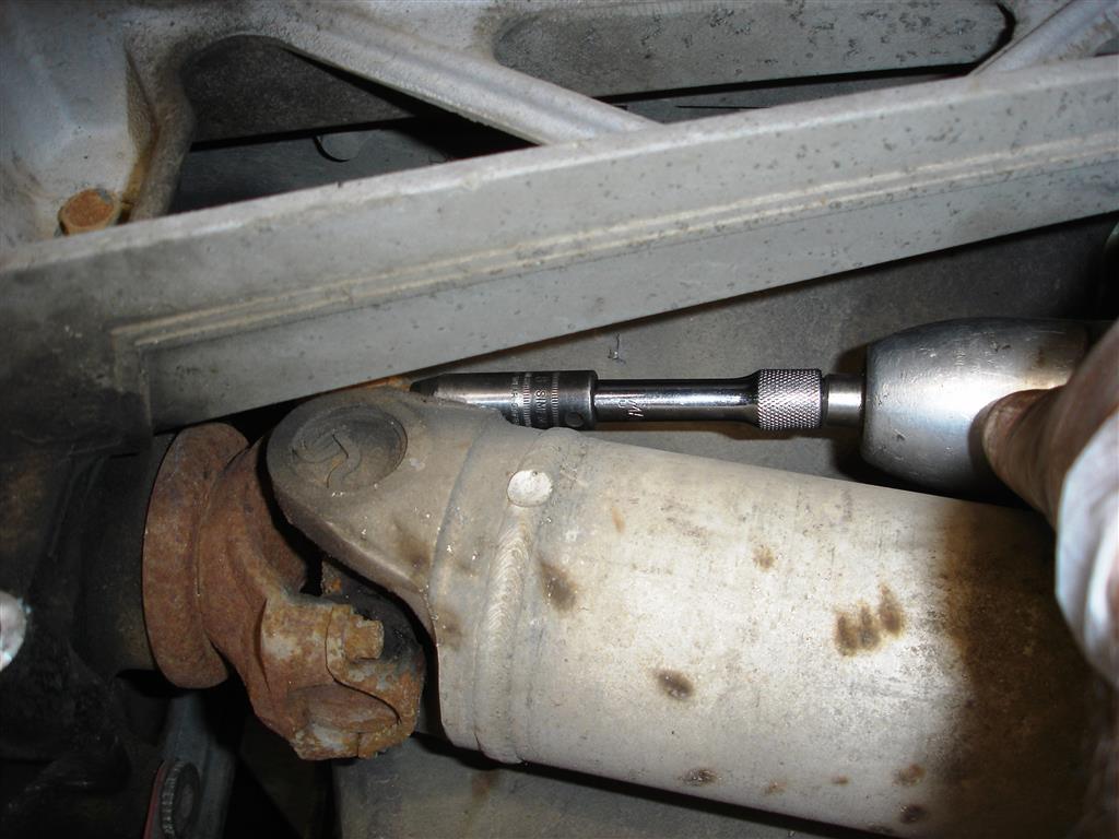
Before the differential can be removed, the 21mm long bolts placed vertically in the front of the differential must be removed. These bolts have a 21mm nut that is free spinning; I use a short 21mm wrench to get it into position to hold onto the nut. The driveshaft must also be removed with an 8mm socket. Finally, the torque arm must be supported as the differential is lowered out of the C4.


The anti-roll bar is removed from the chassis. Removing the spare tire and carrier make this easier. 13mm nuts hold the fuel tank crash protection retention straps. The 13mm nuts holding the anti-roll bar retainers are then removed.


This shows the link being removed from the anti-roll bar. The same 18mm nut and 15mm bolt are removed from the spindle knuckle.


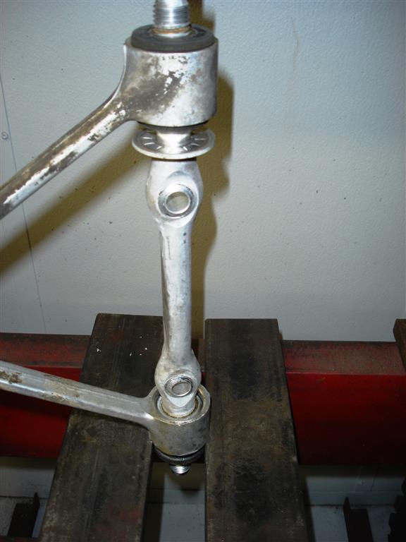
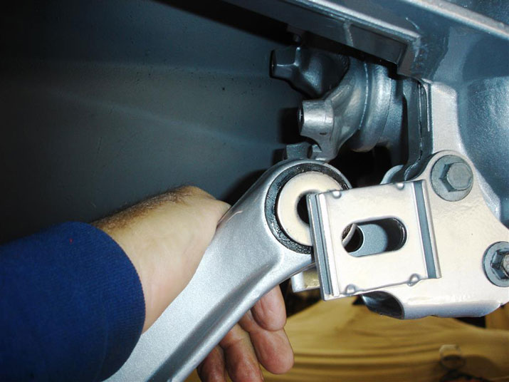
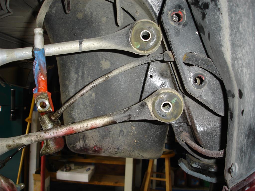
I remove the spindle rods from the chassis so the knuckle assembly can be brought to the bench for disassembly. The process can be done a few ways. If you are just replacing spindle rods or bushings the bolts can be removed from the bracket. You have to be careful with the nuts during disassembly or assembly, as they can drop into the chassis if they fall out of the wrench. You can remove one spindle rod at a time and replace it or the bushings, or leave the spindle knuckle in place.


The spindle rod bolts, brake caliper with parking brake cable mount and brake hose are removed. The spindle knuckle assembly is then ready to come out.


With the spindle knuckle assemblies on the bench, the spindle rods can be removed with the 24mm socket and wrench. The spindle rods can be removed completely with the spindle knuckle assembly in the car, but they must be supported. Do not rely on the brake hoses and parking brake cables to hold them in place.

Suspension Bushing Service


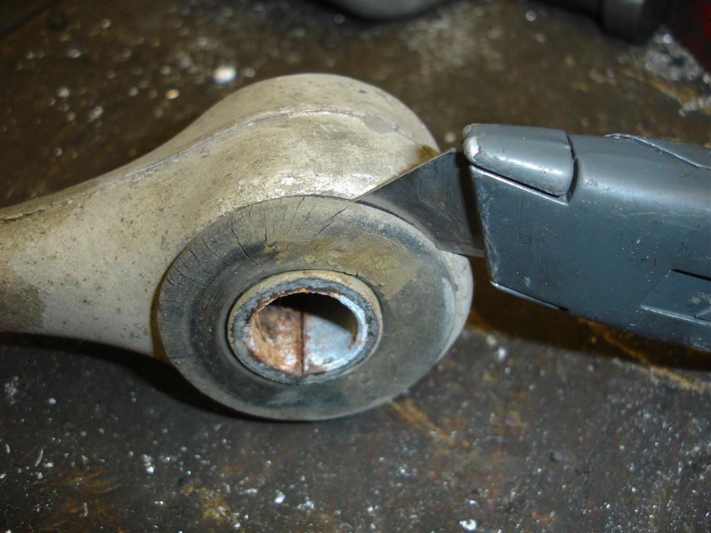
There are a few ways to remove the rubber bushings: burn them out, force a drill bit into the rubber until it comes loose or do them in this manner. I begin by cutting the outer portion of the upper control arm bushing that protrudes past the arms bushing opening. This keeps the rubber from wedging itself between the washer and arm end as the bushing is pushed out. The upper control arm shaft will be pushed out through this bushing first using the small washer to push the rubber out.


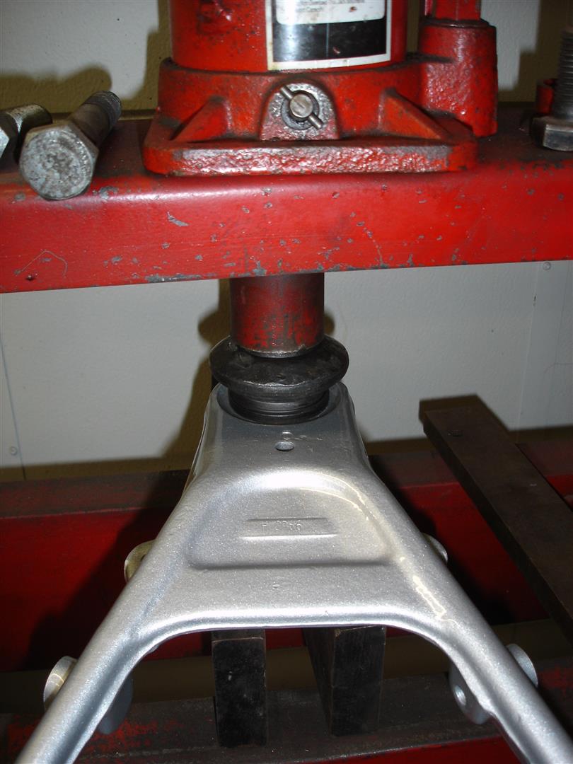
I have placed the upper control arm in the press, capturing the arm end on the two metal plates and pressing on the shaft itself. You can see the small washer is pushing the rubber out of the arm with the shaft. One very important thing to watch for is shaft movement through the upper bushing; it must pass through without restriction. If the shaft is caught on the upper bushing during the process, the shaft will collapse the aluminum arm easily. If necessary, a piece of steel can be used to prevent the arm from collapsing. Place it from one side of the arm to the other. To date, I have never had a shaft stick in the other bushing. If the shaft does not rotate when the nuts are removed from the shaft, beware. Chances are the shaft is stuck.


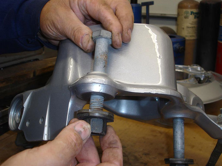
On the opposite end, a washer head bolt is used to push the metal sleeve out of the rubber. Once the sleeve is out, the rubber is easily removed.


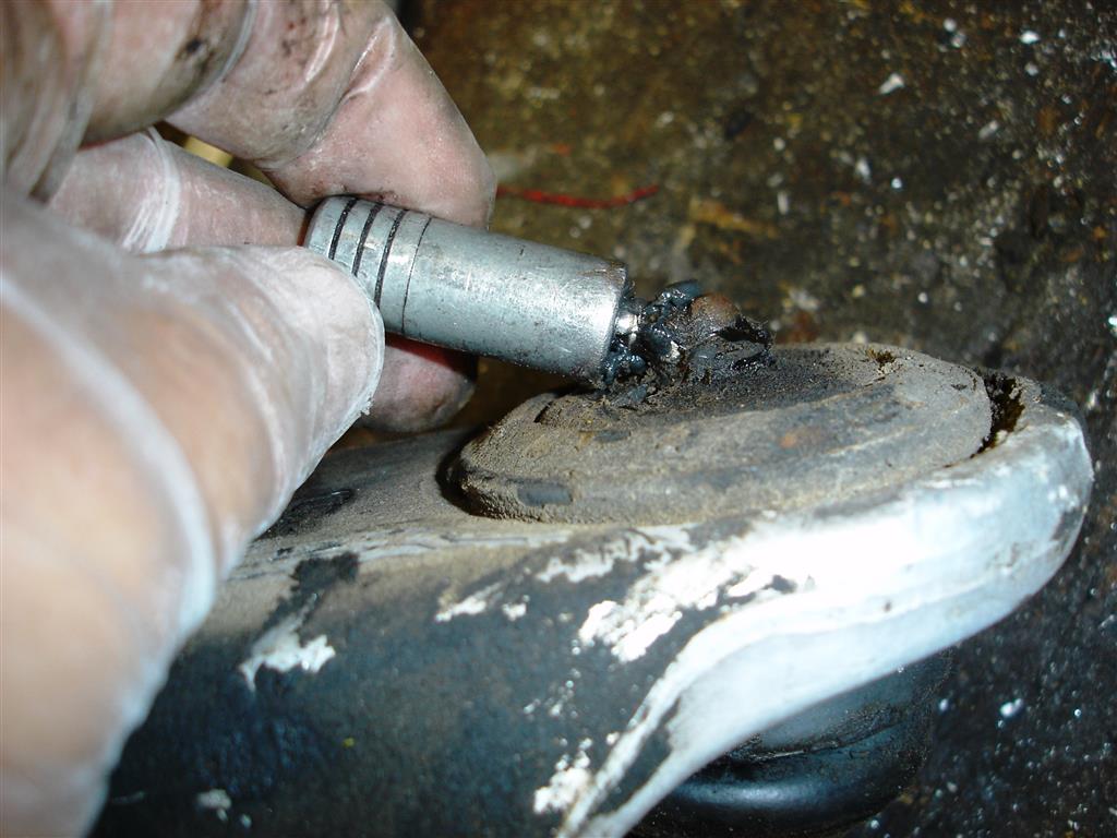
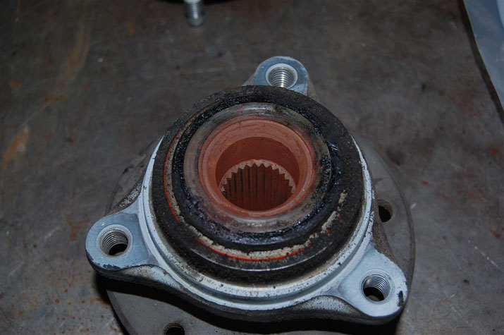
FYI: if the grease gun will not go onto the lower ball joint fitting, it is time to replace the joint. As the ball joint wears, the wear indicator draws inward, making it difficult to connect the grease gun. Replacing the fitting with a straight fitting makes it difficult to grease with the wheel in place and is dangerous because the ball joint is worn beyond its service limits.


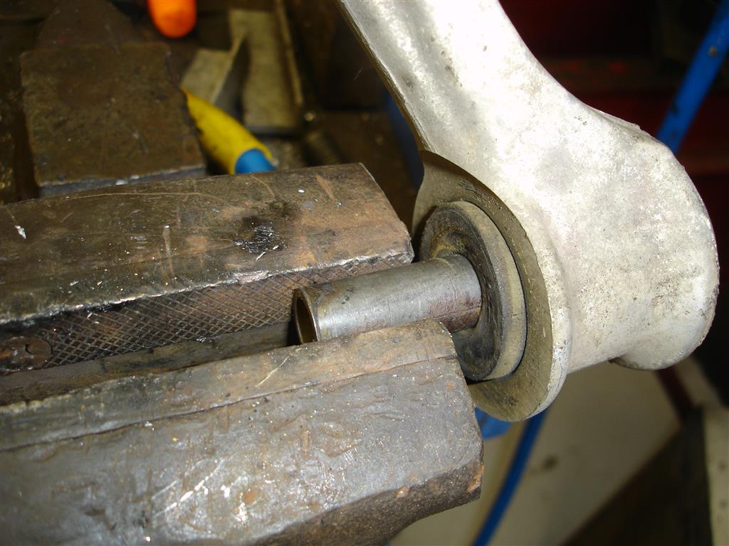
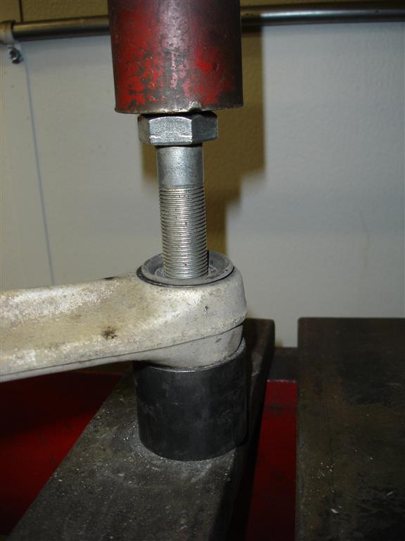
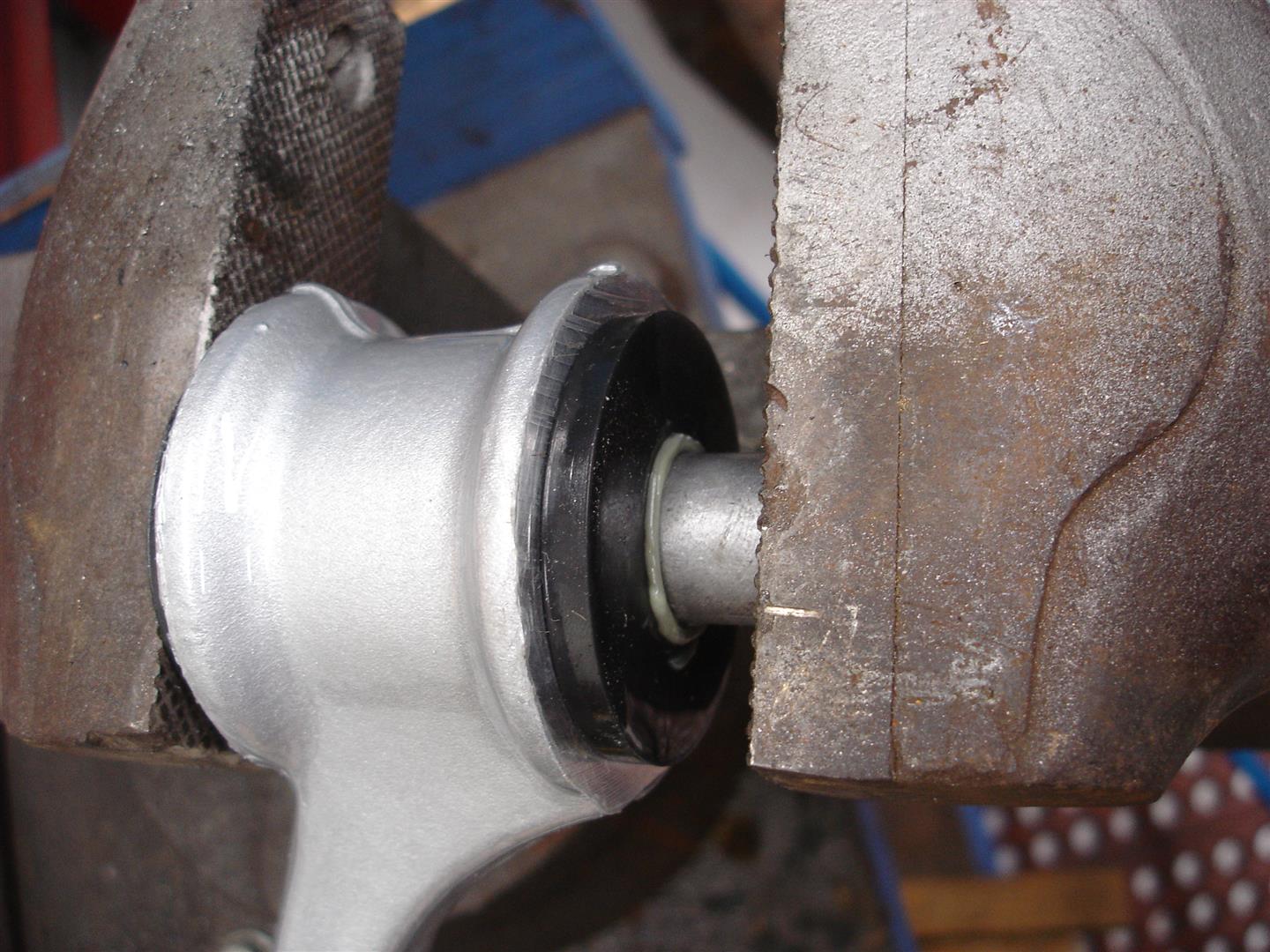
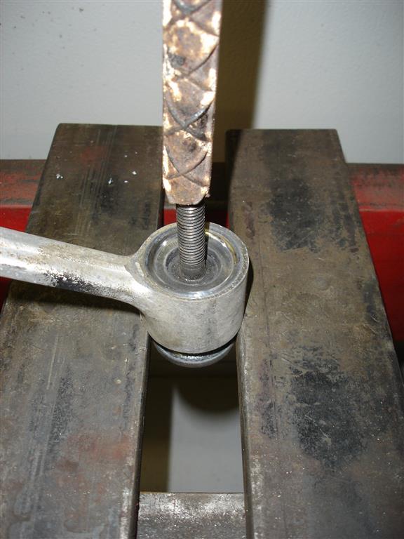
The lower control arm bushing removal begins with removing the steel sleeve. This may seem simple and it is, as long as the correct diameter pushing tool is used. If the diameter is too large, it will be stuck in the bushing like the sleeve was. I use a hydraulic press for all of the bushing removal operations; if necessary, your local automotive machine shop should be able to handle this.


Once the sleeve is almost out, it can be grabbed by a vise and pulled out completely. The sleeve must be fully removed to simplify rubber bushing removal.


The bushings outer rubber edge was cut off to ease bushing removal. The press is used to push the rubber out with a sleeve placed on the lower part of the control arm to receive the bushing.


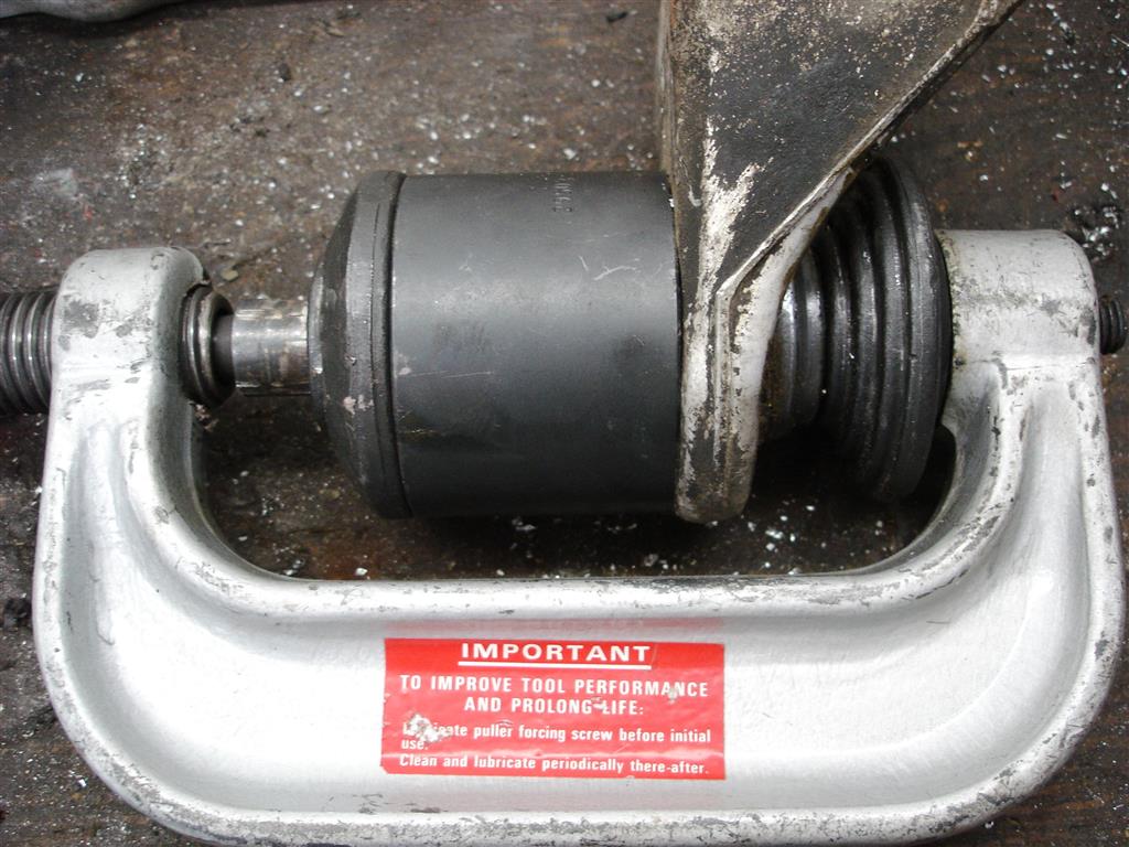
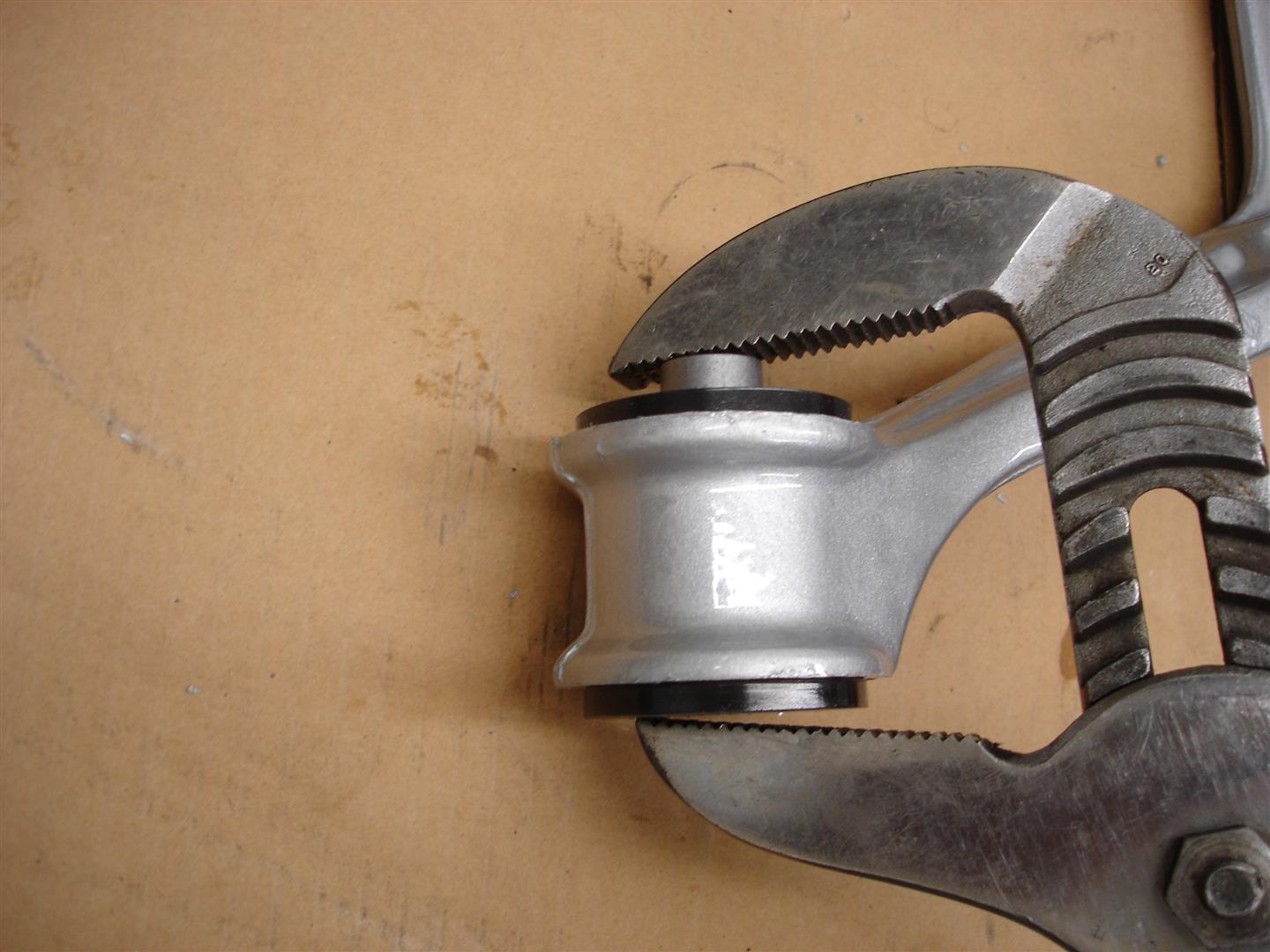
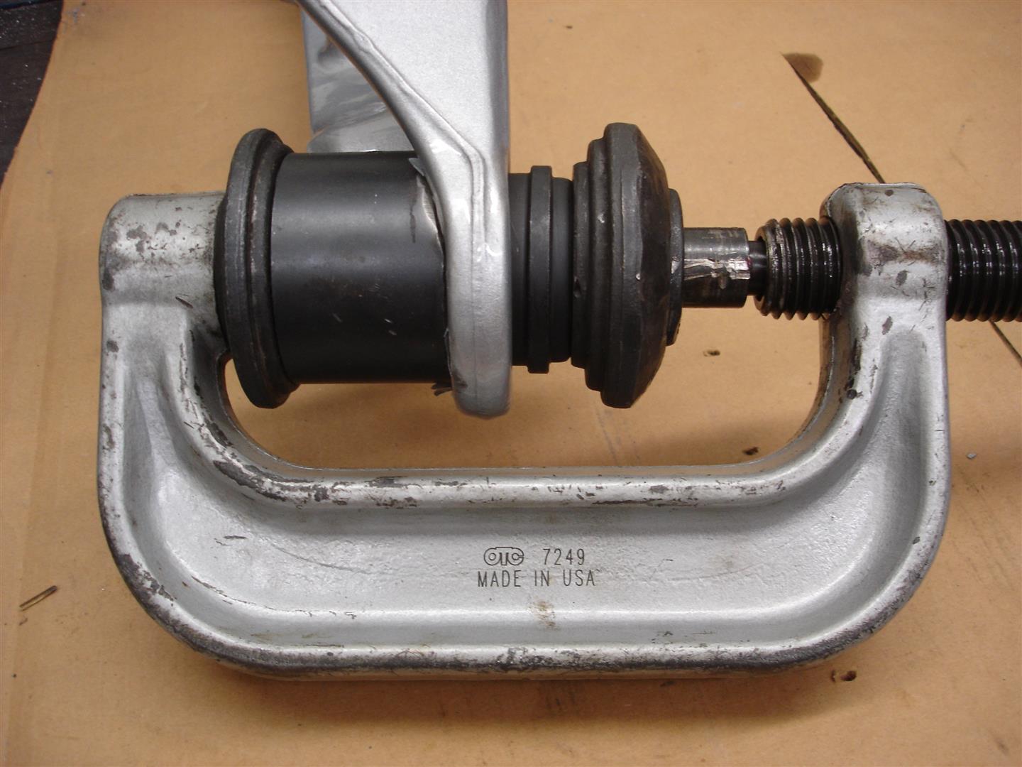
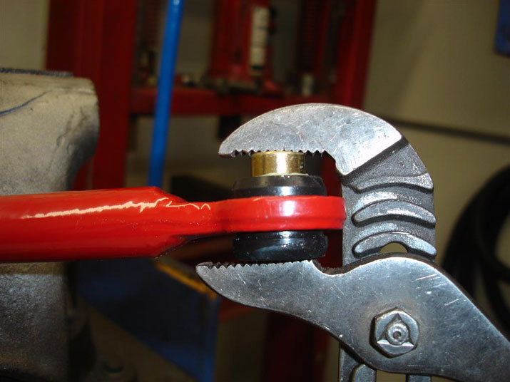
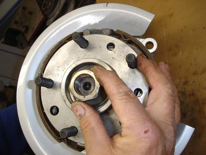
This super duty C-clamp is used to remove and install the lower ball joints. If you do a web search, they can be found for under $100.00 and are very useful for many suspension/driveline projects.


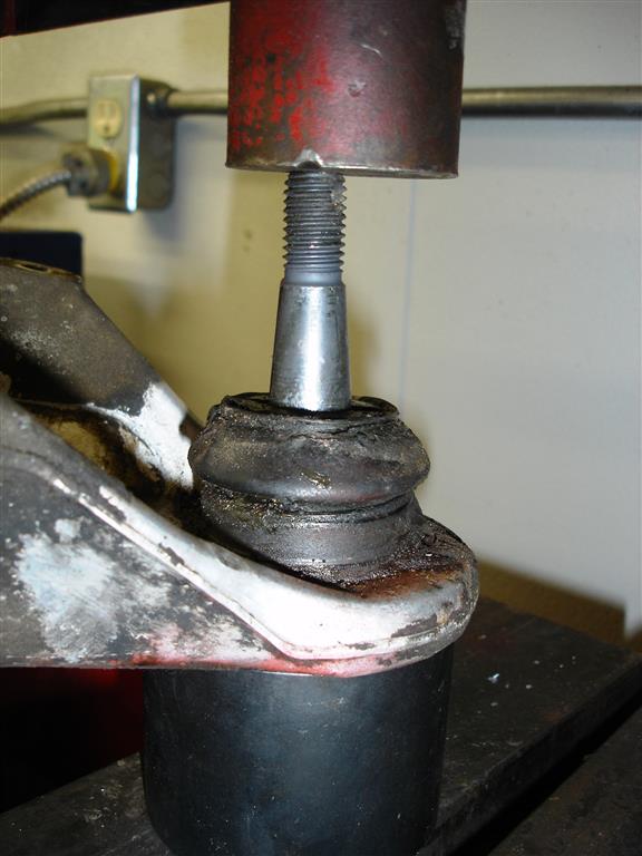
A hydraulic press can also be used for ball joint removal.


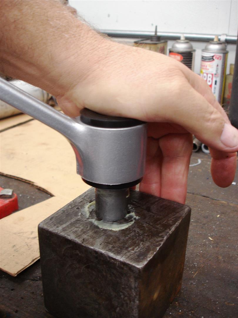
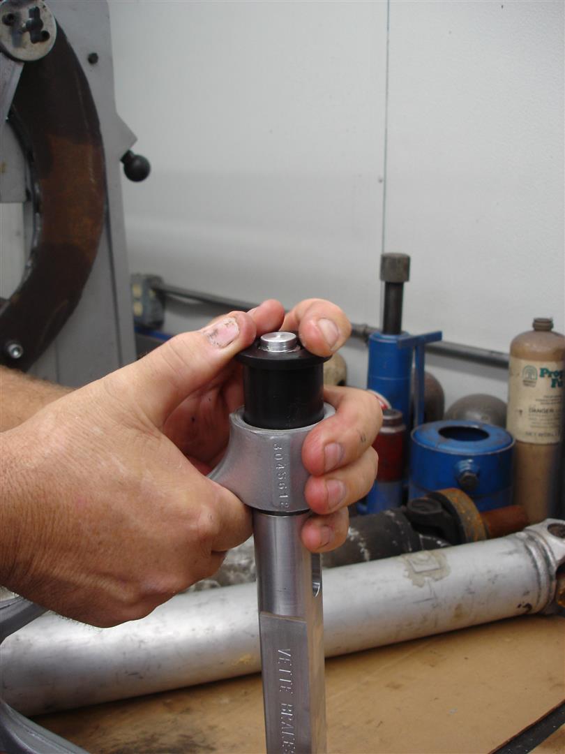
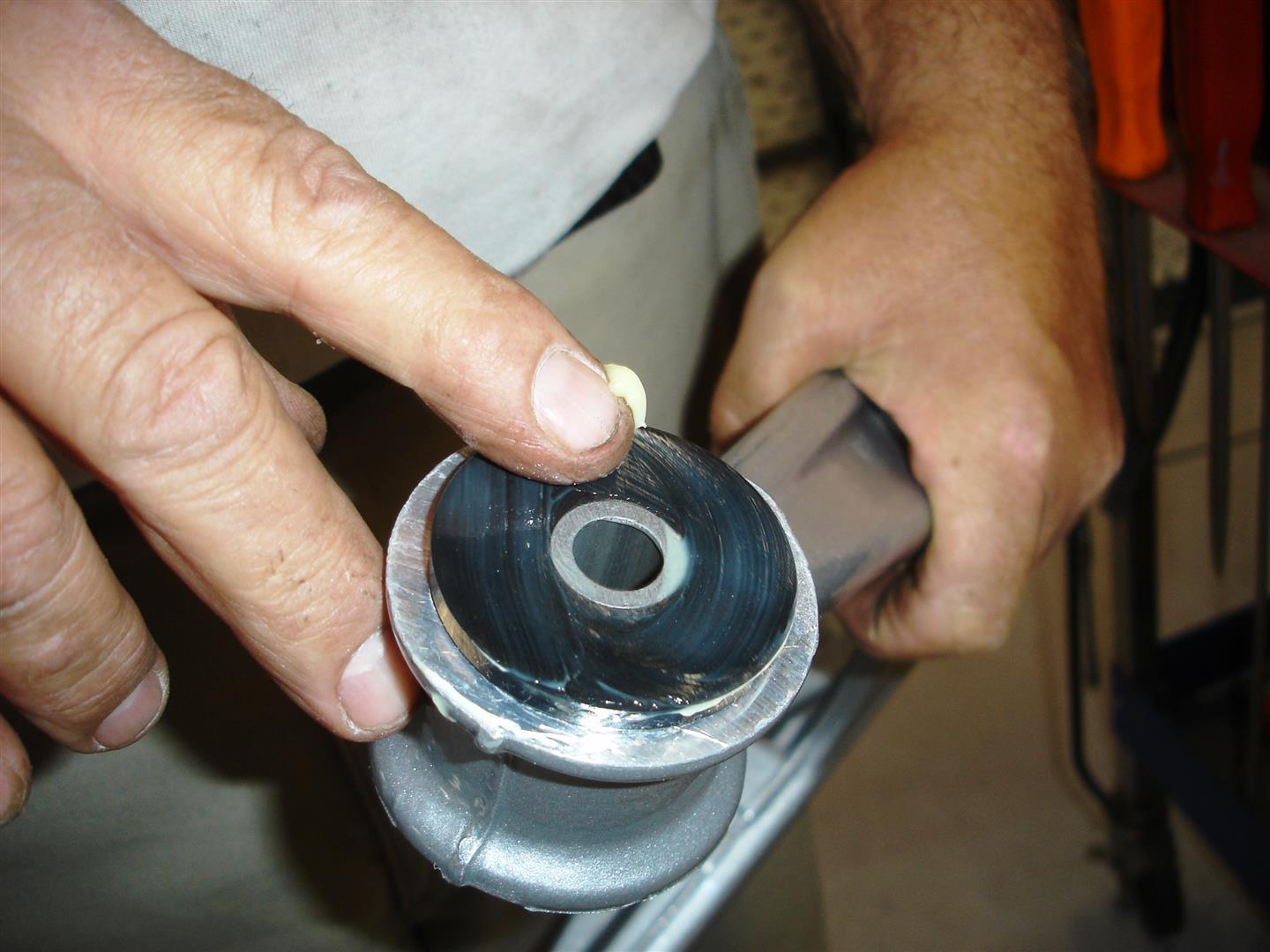
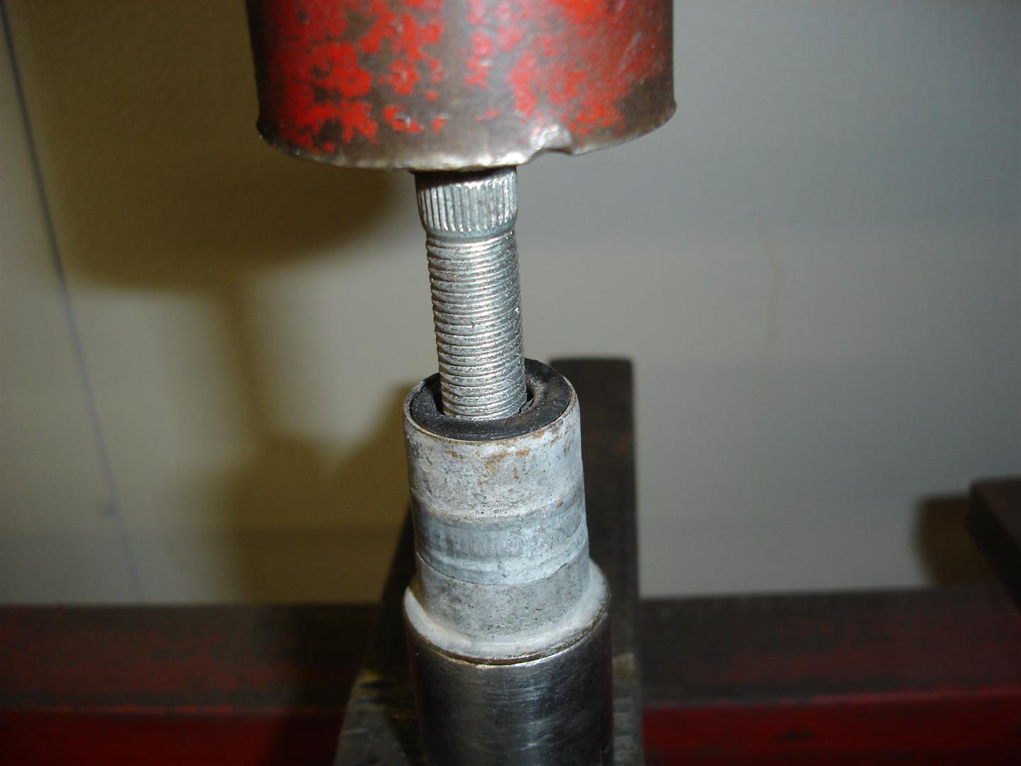
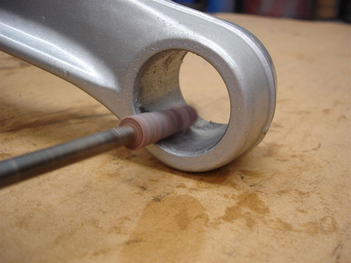
The rear spindle rods get the same rubber removal to ease disassembly. Like the upper control arms, the sleeve is pressed out. the rubber is then easily removed.


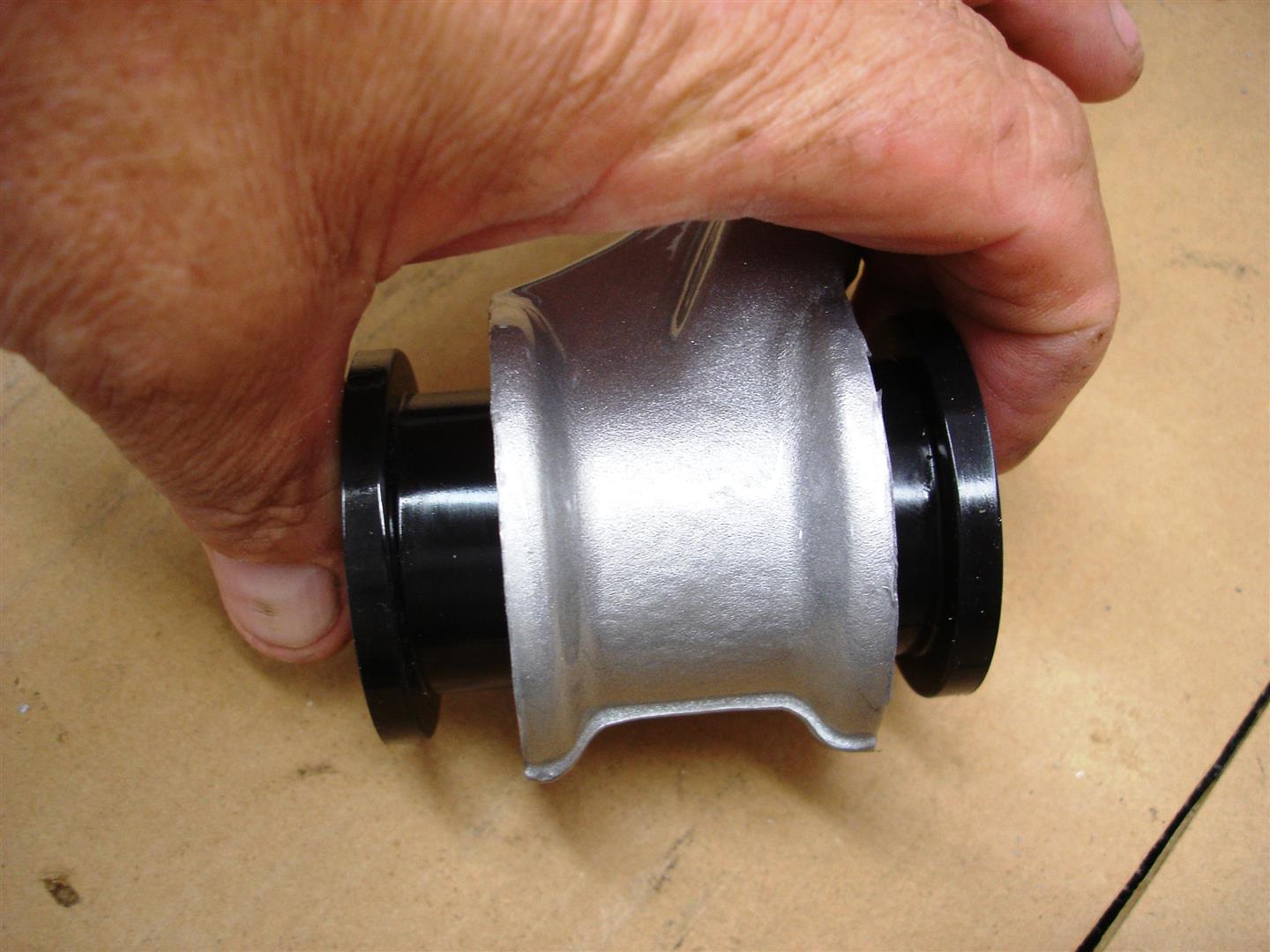
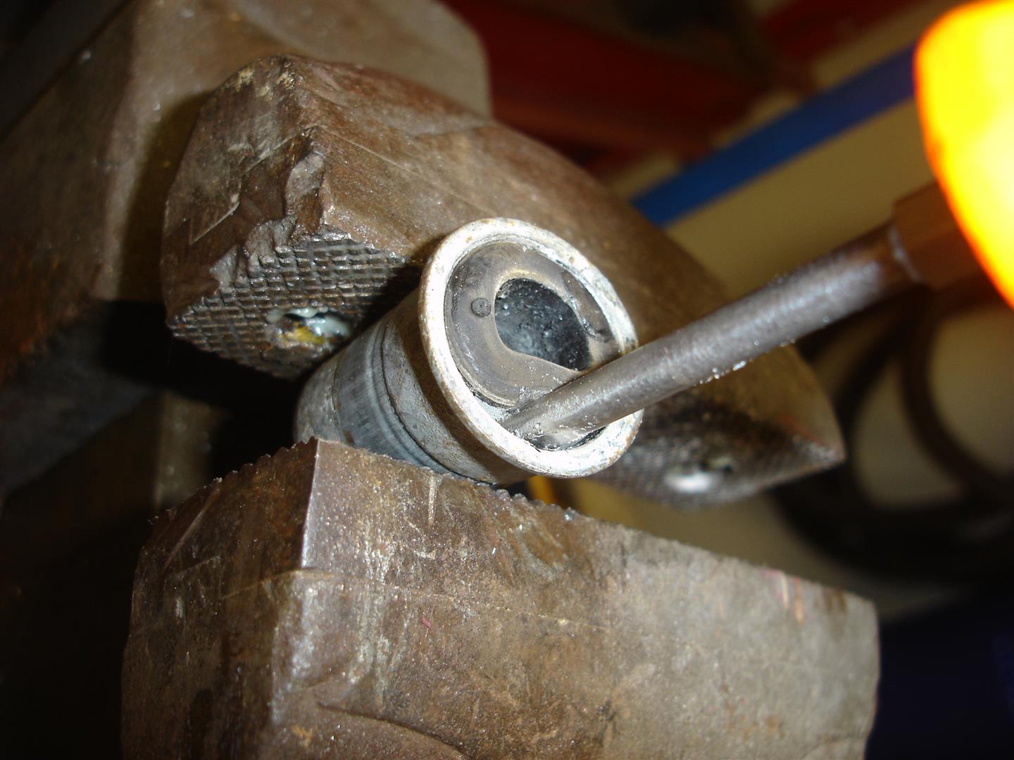
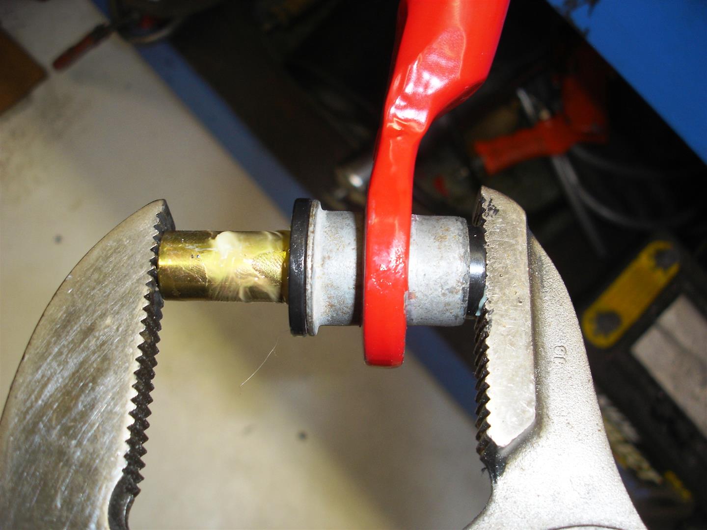
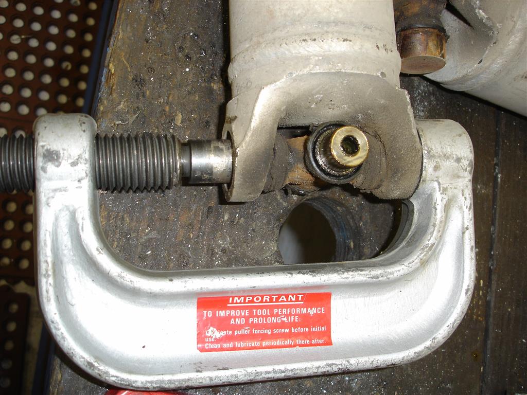
The one exception is rear camber rod bushing removal. There is no trimming required; the sleeves push out of the thin rubber bushings easily. The C-clamp can be set-up to do the same work as the hydraulic press. The C-clamp tool kit comes with sleeves and pushing/pulling plates to fit just about any set-up you need. There is no reason that it would not work pushing the sleeves and bushings out of the control arms.


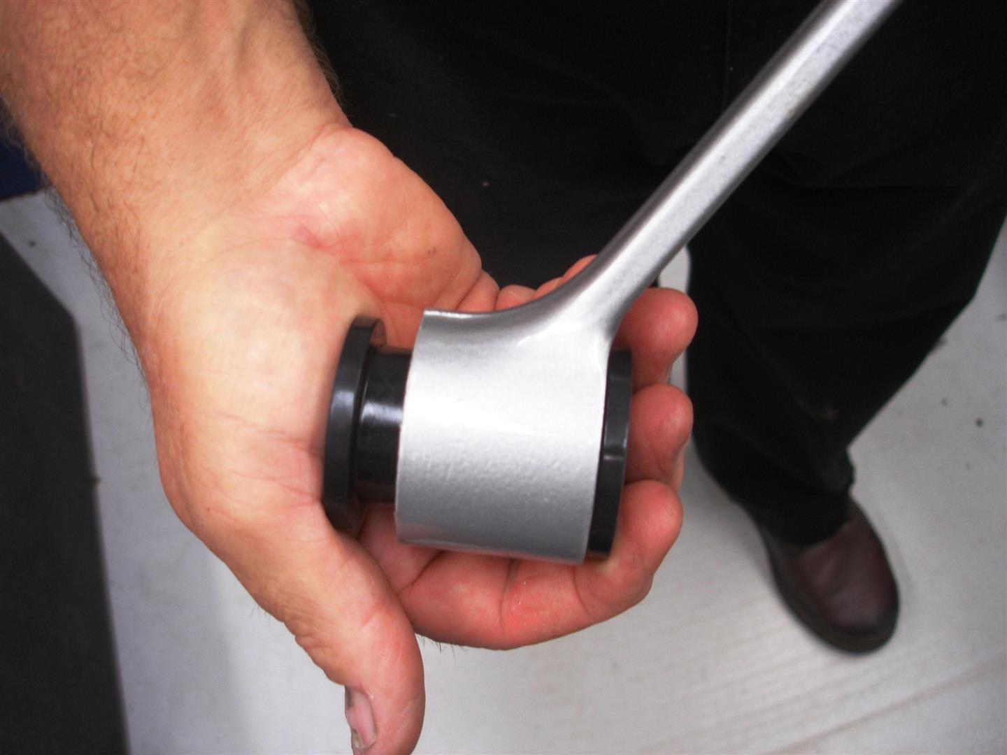
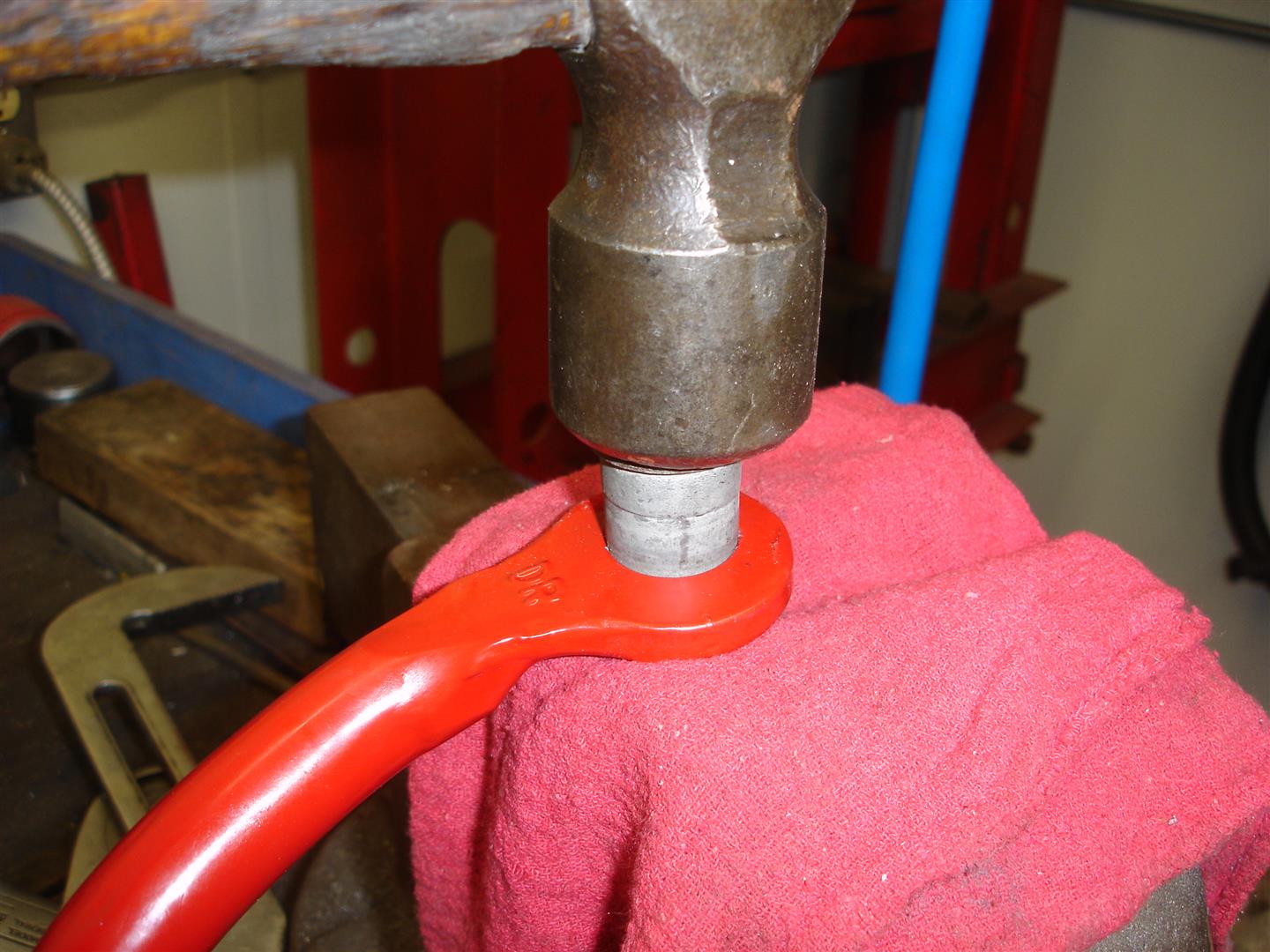
This is how all of the bushings can be removed once the sleeve is out. They are not vulcanized to the control arm or camber rod ends.


This is another use that the C-clamp was designed for, pushing the universal joint cups out of the yokes. Always remember: the aluminum is tough but can be easily distorted when using a press or the C-clamp tool. If the object to be pushed out does not move with a few turns, back off and make sure the tool is not catching on something.

This is the first installment of a C4 suspension overview series. Click to view the second article, Click to view the third article

Story and photos courtesy Chris Petris
 
Corvette Front Suspension Bushing Service


This is the second installment of a C4 suspension overview series. Click to view the first article, Click to view the third article.

Once all the original bushings are pushed out and the parts cleaned up bushing installation can begin.

There are a couple of things to be aware of before the first bushing is installed. The bushing bore must be clean and free of any snags of metal that may have been raised during the bushing removal process. Powder-coat or paint may also be in the bushing bore and should be removed to ease bushing installation. A raised area, whether it be paint, powder-coat or gnarled metal, causes the bushings inner sleeve to drag on the urethane, preventing smooth suspension movement. Unlike rubber bushings, urethane bushings should rotate smoothly throughout their suspension range of motion (one of the major reasons for the change to urethane). Too much clean-up of the bores is also a concern: the bushing should require effort to push in. You should be able to squeeze your hand and force the bushings in.

The bushing sleeves take some force to push in. It usually takes a vise or a large pair of pliers to aid in the sleeve installation.


These lower control arm bushings from a Corvette Central urethane bushing kit are being pushed in not quite as easily as this photo shows. I usually start the bushing in the control arm with the arm end sitting on the work bench, then the bushing is pushed into the bore. Note there is no lubricant silicone on the bushings. They should not rotate in the control arm bore. The outer raised edge of the bushing must sit flat against the control arm end. If not, you will have a difficult time getting the arm end to go into the chassis mounting point.


Now the bushing’s sleeve area should be lubricated with the supplied silicone grease. It’s a good idea to wipe the lube inside both bushings.


The sleeve also should be lubricated with the supplied grease, coating the entire exterior of the sleeve.


This is one way to push the sleeve in place. Note the grease building up as the sleeve is pushed into the bushing. The sleeve may seem to be tighter in the bushing than the bushing was in the bore; it is not though, the sleeve has to be pushed into the two separate bushings. Once the sleeve passes through both bushings, they become aligned and the sleeve should rotate without moving the bushings in the bushing bore. If the bushings and sleeve rotate together, the bore is too large or the sleeves outer diameter is too large. In some cases a piece of Scotch-Brite can be used to polish up the sleeve to remove any burrs that may be causing the extra tight sleeve fit. Remember: the sleeve should be tight, although it should rotate without extreme effort for the best suspension flexibility during road anomalies.


This large pair of Channel-lock pliers will suffice for sleeve installation. If I were using them, I would have put a piece of wood like a paint stick on the bushing side to keep from marking the urethane bushing during the big squeeze. I also put the pivot bolt through the sleeve to make sure there are no raised ridges causing the bolt to stick as it is pushed through. If the sleeve has any obstructions causing the bolt to be tight or not push through easily, use a rat-tail file to smooth the inner sleeve bore area.


Ball joint installation is next; here I am using a sanding roll on a high speed grinder to remove any paint or nicks that might be in the bore. Use caution here: do not remove any control arm material; only paint, powder-coat or debris. The ball joint relies on a press-fit and it must be tight once installed.


I prefer to use a hydraulic press for ball joint installation. It’s much easier to square up the ball joint during the big push. On the bottom side, a receiver sleeve bigger than the ball joint itself is used and then a disc sits on top of the ball joint during installation. You need to watch that the ball joint goes in straight, if it goes off to one side stop and push the ball joint out and try again.


This OTC ball joint press works well for installing the ball joints when the control arm is on the car. You do have to be careful: if you look closely, the ball joint is off to one side as it is being pushed in. This is not good, as it goes in at an angle it tears material away from the bore and it may seem tight but it really is not. If the ball joint goes off too far off center, it can break the control arm. Patience is the key. Monitor the ball joint as it is installed and take action if it is not going in square.


The same procedure is used for the upper control arm urethane bushing install. Start by installing one set of bushings in one end. Avoid putting any stress on the control arms two strut pieces, as they can be bent or worse yet broken. Remember: no grease on the bushing as it goes into the control arm end.


I have found that the sleeves go into the bushings slightly easier on the upper control arms. On its side they can be pushed in this manner. Note the silicone grease on the sleeve; apply grease to the sleeve and inner bore.


This upper control arm shaft is an experimental piece and is not available to the public. The assembly concept is the same though: place the washer on the shaft’s end before it passes through the bushing previously installed. This washer is very important: it prevents the upper control arm from moving around when side loaded. The factory upper control arm washer must be reused during assembly with a factory upper control arm shaft. Make sure any rubber is removed and the surfaces are smooth.


Now the smaller diameter bushing is pushed into the control arm. Sometimes they can be pushed in by hand, although I find these bushings require more effort.


This hammer and socket works well and is required most times to seat the bushing into the control arm. First and foremost, make sure the control arm is supported before any load is applied during the bushing install. Note the plastic hammer. It should not require a tremendous amount of effort to push the bushing in place. Make sure your socket or installer does not contact the control arm shafts aluminum threads as it installs the bushing.


Here the sleeve is being installed into the bushing. The arm is pushed downward by hand pressure only to seat the sleeve. Apply plenty of silicone grease to the sleeve before installation. The control arms shaft threads come very close to the vise jaws during this procedure. Care must be taken to avoid damage.


Now the part where good judgment comes in to play. GM does not have a recommended torque setting for the upper control arm shaft nuts. The upper control arms were not to be serviced; hence they have no guidelines to go by. It is very hard to determine what the initial torque was because a locking compound was used on the threads. In the shop, we apply blue Loc-tite to both shaft end nuts and torque them to 35-40 foot pounds. This may not seem very tight but we are dealing with aluminum threads. Once the project is complete and has been driven a couple hundred miles we recommended that the torque be checked. So far we have not had any problems with this torque setting. Keep this in mind, unlike the rubber bushings that would keep the control arm from disassembling if the nuts backed off the urethane bushings will come out. What happens next is total loss of control of the spindle knuckle.


Front spring installation is next. Here we are installing a stock spring rate in this 1985 Corvette for a smooth, all road surfaces ride. Many opt for a stiff front spring in the belief the tire/wheel assembly will be pushed onto the road surface, whereas the softer spring will let the tire leave the road surface easier. This is true to some degree if the frame supporting the front suspension is stiff. If not, the stiff spring bounces the tire over the road surface. I’ll discuss the spring rate further as we proceed. Always check the inner bottom side of the crossmember for any raised metal that might gouge the spring once it is in place. The spring is put in place and pivots loosely installed until the control arms are in place.


I apply a liberal amount of silicone grease to the urethane end cushions of the front spring for smooth spring action. These urethane spring pads are replaceable and may require replacement after 5-6 years depending on your road conditions. GM used rubber pads that tend to last longer but you lose road feel on track set-up Corvettes. The spring pivot mount retainers should be torqued to 48 ft lbs. I wait until the spring is in place with the spindle knuckles connected to both the upper and lower control arms before torqueing. This flattens out the spring and assures the spring is centered in the mounts.


The lower control arms are installed with more of that silicone grease on the outer bushing surfaces. It is critical that the bushings fit tight in the pivot to prevent suspension geometry changes. That means that the inner sleeve should be level or slightly below the outer surface of the urethane bushing.


The tight fitting lower control arm bushings require some help with this plastic dead-blow hammer during installation. Try to keep the control arm ends going in even avoiding a binding condition.


Once the sleeves are close a line-up bar is used to center the sleeves for bolt installation. It works best if both sleeves are centered before attempting bolt installation.


The hardened original GM bolts are installed with an extra thick washer at the bolt and nut sides. Because we are using urethane bushings, the bolts can be tightened and torqued now. The spring makes access to the nuts somewhat aggravating but not impossible. It is always recommended that the torque wrench be applied to the nut if at all possible. This assures an accurate torque reading whereas the bolt as some inherent twist and the applied torque will not be as great. The lower control arm nuts should be torqued to 82ft lbs. If the bushings are set-up correctly, the lower arms should move with some tension, not in a rigid state. If they just fall down on their own weight, the sleeves are too long and the bushings will move around and cause geometry changes. If the only way to move the control arm is with a jack the bushings are too tight and smooth suspension travel will not occur which is what we want.


This early 1984-1987 lower control arm has had the shock absorber/sway bar plate installed after the control arm is in place. Later 1988-1996 lower control arms do not use this plate and have the sway bar and shock absorbers mounted directly to the control arm. The later control arms are a better choice for a serious Road Race or Autocross competitor. The shock/sway bar mount plate requires constant checking for tightness when the 84-87 Corvette is used on track days. The tall jack stand is placed under the lower ball joint to prepare the control arms for spindle knuckle installation. May seem obvious but the grease fitting should be left out or taken out during this procedure to avoid breaking it off in the ball joint.


The shocks are installed using the original GM metric bolts into the J-clips. The J-clips make the install easy but they are a weak link to some degree. They do not have the same holding power as a nut. The bolts should be torqued to 19ft lbs. Later 1988-1996 have through bolts and nuts holding the shocks the nuts should be torqued to 20ft lbs. The sway bar link mount to plate bolts and nuts are torqued to 22ft lbs.


Once the upper shock mount is in place, the jack holding up the lower control arm can be released. I usually do the assembly this way to give me plenty of access to the components without a jack in the way. These Bilstein shock upper studs make it simple to correctly tighten the upper mount. They have a shoulder on the stud that the upper washer should be seated on; this prevents over tightening and cushion damage. The locking nut that Bilstein provides with the shock requires the use of an Allen wrench to prevent spinning the shocks shaft. A turn or maybe two most likely will not cause an issue. Spinning the shaft can cause the shaft to come out of the piston. Once the washer is seated, the nut should be torqued to 19ft lbs. In most cases, the cushions have enough drag once the washer is seated to allow the use of a torque wrench for the final check. Some aftermarket shocks do not have a shoulder for the washer to seat against. Run the nut down until the cushions begin to bulge. If not, the cushions will be crushed and split over time.


Now the spindle knuckle is set onto the lower ball joint stud. Note the washer between the nut and spindle knuckle: it must not be left out. The washer prevents aluminum damage as the nut is torqued. The ball joint stud is torqued to 50ft lbs, then the nut turned to the first available opening in the castellated nut and ball joint stud hole. Never back off the nut to align the cotter pin hole. A note of caution: if any paint or refinishing material is in the spindle knuckles ball joint stud hole, it must be removed or an improper torque reading will result. As the debris breaks away, the stud becomes loose. Eventually the loose stud will ruin the spindle knuckle as it wobbles around.


I replaced the original rubber tie-rod end boots with these Corvette Central urethane replacements. Although they are not retained to the tie-rod end as the originals, they will last much longer and cannot be blown out from over-greasing. All too often we find the inner wheel drum full of blobs of grease and dirt from blown out ball joint and tie-rod end boots. If greased properly (2-3 pumps of grease), the seals will not blow out or have major blobs of grease oozing out of the joints. If the urethane joints or ends are over-greased, wipe all the excess grease off and you will prevent dirty inner wheel drums. Another fact the entire front end should be greased 3 times for proper grease penetration. One time while the steering wheel is centered, again when rotated fully left, and finally when rotated fully right. It does not matter how you go right to left or vice versa; the rotation assures even greasing. The old adage applies here, a picture paints a thousand words and those grease/dirt blobs not only look bad they affect wheel balance. Although not a major concern, over a long period of time cumulatively it can alter wheel balance.


Two procedures here: the tie-rod end nut (with the washer under it) should be torqued to 32ft lbs and then tightened to line-up the cotter pin hole. The wheel bearing assembly is installed and (the nuts) torqued to 46ft lbs. If any coatings were applied, make sure the bearing and spindle knuckle seat areas are clean and free of any coatings. As the bearing works on the coatings between the mating surfaces, they break apart and the torque you think you have is much less.


I go back to the bench and prep the sway bar bushing outer sleeves for the new urethane bushings. The sway bar end bushings come from the factory as one assembly; they are easily tapped out of the ends. The sleeve must be pushed out of the rubber, a socket is used as the receiver and a wheel stud pushes out the sleeve. I have access to a press, a bench vise will also work for this procedure, just takes more effort. Make sure the pusher tool you use is smaller diameter than the original sleeve or it will be caught in the rubber.


Once the inner sleeve is out, the rubber is torn away from the outer sleeve and forced out. Remember we need this outer sleeve so take care to avoid distorting it. After the rubber is removed any traces of the rubber need to be removed with a knife, scraper or coarse sandpaper so the bushing fits without binding during installation.


The clean outer sleeve is tapped into the sway bar end until it seats on the sleeve’s shoulder.


The urethane rubber bushing from the Corvette Central sway bar end link kit is easily pushed in by hand into the outer sleeve. The inner sleeve is lubricated and pushed into the urethane bushing. This large pair of Channel-lock pliers should do the job without too much effort. If a large hammer is required for the inner sleeve install, chances are the outer sleeve has some old rubber left behind and the sway link will be too tight.


Your urethane bushing kit will come with this auxiliary urethane sleeve that fits over the existing outer sleeve. The auxiliary outer bushing prevents the inner bushing from coming out of the end link during loading. The belt sander is used to make the outer bushing level with the inner steel sleeve. If the auxiliary bushing is not machined, it will bind the assembly in the end link and eventually tear the auxiliary bushing and the assembly will become loose.


One of the first questions when ordering a urethane bushing set will be the sway bars diameter; GM used a few different diameter sway bars depending on the suspension package. A pair of snap ring pliers (such as these shown) helps a bunch when trying to force a urethane bushing over the sway bar. Silicone grease is applied before the bushing is installed and after to make sure the well worked sway bar is lubricated. Due to the open location of the sway bar pivot bushings, they often end up with plenty of dirt and debris mixed with the grease that finds its way between the bar and the urethane bushings. This is often the place that the urethane squeak begins. To avoid the squeaks while preventing sway bar and bushing damage, an annual disassembly and cleaning is recommend for those who use their Corvette on a daily basis. I have seen the steel bars worn with deep gouges from road dirt and grease as it chews into them. Of course the urethane bushings also wear and become loose overtime.


Once the bushings are installed with plenty of lube is on the bar and bushing, the assembly is put in place on the frame rail. The best policy is to install all the bolts and turn them in about half way. This makes installing the end links easier. Once the end links are installed, the pivot mounting bolts are torqued to 40ft lbs. It is very important that the sway bar pivot mounting bolts hold the 40ft lbs of torque. If the bolts or bolt hole treads are questionable and the bolts pull out, the sway bar cannot do its job. I often have to install a 10mm x 1.50 heli-coil into the frame bolt threads to assure a tight bolt. Heli-coil kits are available from most auto parts supplier and major hardware chains.


Now the end links are installed placing both links driver and passenger side onto the lower bushing with the other end on the sway bar. I find it easier to install the lower bolts on both sides first, placing them with the bolt head towards the rear of the car. If the bolts are turned around they can dig into the shock tube. I then install the upper bolts through the sway bar bushings. After all the bolts are installed, I snug them up and torque them to 35ft lbs.


This is another C4 that had upper control arm work that represents a factory control arm shaft. The upper control arm shafts use the concave thick washers to center and retain the shafts. Make sure the concave side goes towards the control arm shaft, there will be two of these concave washers, one on each side of the shaft. The lock nut goes on after the concave washer. Once the alignment is completed, the nuts should be torqued to 37ft lbs. I always check the torque of these bolts after a Corvette returns from the alignment shop.


The shim pack goes between the frame riser and a spacer. As mentioned above, a concave washer goes against both sides the control arm shaft. A spacer is also placed against the concave washer on the inside to preset caster and camber. 1984-1985 Corvettes have a thin spacer at the front control arm shaft retaining bolt and a thicker spacer at the rear bolt. This was for the maximum 3 degrees of positive caster that GM suggested in their Alignment Specs. By 1986, GM revised the positive caster to 6 degrees for better high speed stability. This was long before any suspension component upgrades took place in 1988. In the shop, I swap the thick spacer to the front, placing the thin at the rear to achieve at least 6 degrees of positive caster for the best possible handling. If you look at any original 1986-1996 Corvette upper control arm, you will find the washers are thick at front thin at the rear. Another note: if you look at the factory service manual, they show placing the thin spacer up front until the 1989. This is because the manuals are not completely rewritten until a new generation is on the scene. The alignment shop will install the correct amount of shims to set alignment. It is always best to record where the shims were during disassembly and then put them back like they were for the trip to the alignment shop.


I use a deep 18mm socket to access the upper control arm shaft nuts during assembly. When the front wheels are unloaded, the control arm drops down, making the nut much easier to access. The swivel shown should not be used during the torqueing process.


You may have noticed that the upper ball joints were not replaced. Upper ball joints do not wear at the same rate as the lower ball joints. The lower ball joints handle the vehicle weight while the upper joints are for stability. After the control arms are installed, Corvette Central supplied urethane ball joint boots replace the original rubber boots. I use a razor knife, cutting the boot as close as possible to the old boots metal retainer.


Washers placed under the ball joint stud nut are a necessity to avoid aluminum damage from the nut as it is tightened. It is also a good practice to tighten per the GM service manual, torqueing to their spec of 33ft lbs, then turn the nut until the cotter pin hole lines up. Always go tighter to line up the hole. Never loosen. Now the entire suspension gets a once over for cotter pins and correct fastener torque.

On the next installment, we tackle the rear suspension bushing installation and component installation.

This is the second installment of a C4 suspension overview series. Click to view the first article, Click to view the third article.

Story and photos courtesy Chris Petris
 
Suspension-Lead-Shot-11-e1436800286950-715x410.jpg

Corvette Rear Suspension Bushing Installation and Component Installation


This is the third installment of a C4 suspension overview series. Click to view the first article, Click to view the second article.

In this installment, we tackle the rear suspension bushing installation and component installation.

So far I have covered all the C4 suspension disassembly and have the front suspension assembled. I have also shown how to remove the rear suspension bushings for urethane bushing replacement. Early on we discussed the availability of rubber bushed suspension components. Corvette Central does have the spindle rods available with rubber bushings (584141 Set of 4) or with polyurethane bushings (584090 Upper, 584108 Lower). Camber strut rods are also available with rubber bushings (584151 84-89, 584097 90-96 used/Reconditioned). Corvette Central also stocks good used certified suspension pieces that have gone through an inspection process to assure the best possible condition from a previously used piece. Whether you choose rubber or urethane, I will cover the required steps to install the urethane bushings and all the suspension components. Before we get started assembling, there are a few items to cover concerning the rear suspension.

Rear Suspension notes/tips

The 1984-1985 Corvette used an additional seal that was placed in the rear spindle knuckle to keep dirt, grit and water out and off of the bearing/seal assembly. I prefer to install this seal (Part #584157) in all C4 1984-1996 rear suspension spindle knuckles to keep the bearing and seals clean. The seal fits in the spindle knuckle and the yoke is machined in the same manner whether you have a 1984 or 1996 suspension assembly. There is less chance of water or dirt entering the area between the spindle bearing yoke splines and the bearings seal area.

GM used a ball bearing spindle bearing assembly with two rows of ball bearings for the least rolling resistance. The inner and outer ball bearing set is the same size, keeping them tight for many miles. Depending on the environment they have been through, they can go well beyond 200,000 miles. Hitting large potholes at high speeds will shorten their life, as will out of balance tire and wheel assemblies. The constant bouncing of the wheel/tire assembly beats up the ball bearings. The rear wheel bearing assemblies also have to handle torque application via a splined yoke to the bearing. Automatic transmission equipped Corvettes are typically easier on the splined connection to the bearing and may never experience the typical clicking of loose splines. Although I have seen nitrous equipped automatic transmission equipped C4s wear the splines quickly and the clicking begins. Manual transmission equipped C4s usually all end up with loose rear wheel bearings from on and off the throttle applications. A distinctive click is heard as the transmission is shifted from reverse to drive or vice versa as the splines wear. So far I have not had to replace a spindle yoke to tighten up the clicking splines. A new bearing assembly takes care of that. Proper torque sequence and a revised final torque are critical to long lasting bearings. GM recommends that no weight be applied to a new wheel bearing assembly until it is properly torqued. Installing the bearing and placing the C4 down on the ground for the torqueing procedure is a no-no. GM made some changes along the way concerning the final required torque specification. The 1984 service manual shows the spindle nut torque at 151-177 foot pounds. The 1996 Corvette service manual shows a recommended 164 foot pounds of torque for replacement bearings. To avoid premature loosening of the splines and loose wheel bearings, I torque all of the rear wheel bearings to 175 foot pounds with manual or automatic transmission equipped C4s. Of course you can use a big bar and hope for the best on reaching the required torque. If need be, go rent a big torque wrench for long lasting bearing life.

There is a rear toe link used to control rear wheel toe-in or out. The link spans across the rear of the suspension. It is anchored to the center of the differential rear cover with tie rod ends connecting it to the rear spindle knuckles. Unfortunately many suspension and steering pieces are replaced before this wearable part is replaced. The most obvious symptom of a failed toe-link is rear steer when you accelerate or decelerate. On and off the throttle moves the rear spindle knuckle changing the direction that you are traveling without ever touching the steering wheel. I don’t find many of the toe-links worn but it does occur. The rear steer can be very dangerous with a severely worn toe-link sending you from the inside to the outside of the lane. You can feel a loose toe-link by grabbing the wheel at the 3 o’clock and 9 o’clock position and see if it has any perceptible wiggle. If so, you have found your unintended steering culprit. The toe-link has inner and outer tie-rod joints. Most often the outers wear first. If so they must be replaced while a worn inner tie rod link will require complete link replacement. GM also used two different toe-link tie rod ends; early 1984-1991 #584119 used a male threaded rod end, while the 1992-1996 #584125 used a female tie rod end. Due to the equal length of an early or late toe link assembly they can be used on any 1984-1996 Corvette rear suspension system.

I have seen more than one rear anti-roll (sway bar) bar installed incorrectly causing the anti-roll bar to rest on the rear bumper aluminum support. The anti-roll bar then becomes the rear spring as it binds on the bumper support, keeping the rear spring unloaded. The anti-roll bar ends must go up as they wrap around from the pivot points, it may seem natural that they go down to connect while the rear suspension is unloaded. Once loaded the suspension travels upwards requiring the upswept anti-roll bar ends.

Now it’s time to go over the photos and shows how it all goes together.


The rusty hub and splines indicate a loose spline fit at the bearing drive hub. If you had a clicking noise when putting your C4 in gear or on hard acceleration you found the problem. Note the build-up of grease, dirt and general gunk around the bearing from the lack of the extra seal part number 584157. This hub is out of a 1996 Grand Sport. As you can imagine the manual transmission torque played a role in spline wear.


I’ll start with the anti-roll bar bushing (584101 stock, or 582308 poly) installation. One side of the anti-roll bar link and one side of the anti-roll bar need a bushing pushed into them. Note the copious amount of grease applied to the bushing surface that will be pushed into the link end. The 15/16 inch twelve point socket is used to receive the bushing as it passes through the links rod end. Go slow and watch for chunks of urethane as the bushing is forced into place. If any major amount of material is cut-off during installation the bushing will come out during operation.


The bushing sleeve is pushed into bushing next. A pair of Channel Lock pliers or the vise that was used to push the bushing into place can be used. Plenty of lube should be applied to the inner portion of the bushing and the outside of the sleeve.


This camber strut rod end is being cleaned up with a high speed grinder and 120 grit sandpaper roll. Like the front suspension pieces, remove just the remnants of rubber or any corrosion build-up. Removing too much material allows the bushing to move around and change suspension geometry. Too tight and the bushings will not rotate freely during suspension travel.


The urethane bushings push into the rod ends easily without any lube on the rod end bushing surface. Lube should only be applied to the inner bushing surface where the sleeve rides on the bushing. The sleeve is then pushed into the well lubricated bushings; the vise is used to make sure the sleeve goes in squarely.


Note; during the spindle rod bushing installation make sure to install one thin and one thick sleeve during bushing and sleeve assembly on the four spindle rods. The thick wall sleeve rod end connects to the body while the thin sleeved side connects to the spindle knuckle.


The differential will require installation to hang all the suspension/driveline pieces onto it. I decided to keep the original rubber bushings due to their new like condition. There are new urethane differential support bushings available (#584124) These are not available in rubber at this time. While this may seem counterintuitive with all the urethane bushings, it is for better ride on city streets. The rubber bushings will allow some flexibility over potholes while the urethane bushed suspension components maintain a tight handling feel. Once the differential is in place the bolts are torqued to 89 foot pounds. The two front torque beam bolts are torqued to 59 foot pounds. This is one of those places guessing how tight the bolts are can cause some real aggravation. Over-tightening the torque beam bolts can distort the differential housing causing seal leaks and vibrations.


Now we begin the assembly of the spindle rods to the spindle knuckles. This project required a complete suspension refinishing so I removed the spindle rod supports from the chassis. You may want to install the spindle rods into the support before placing the support on the chassis. You can also leave the support on the chassis. If you do remove it, torque the support bolts to 63 foot pounds.


The spindle rods are installed now, if you decide to install the bracket sans the rods. Beware the nuts can fall into the chassis if you let one go. They can be fished out successfully with a magnet. Remember the thick sleeve goes here or you will not be able to install the knuckle side of the spindle rod. Additionally the spindle rod will fit very loosely at this end if the rods are installed incorrectly. Another thing to remember: the shorter of the two rods is on top.


This project has urethane bushings in the spindle rods so we can torque the spindle rod nuts at this end to 63 foot pounds. I prefer to use the torque wrench on the nut side of a bolt and nut arrangement if possible. In this case I had to do the opposite. The urethane bushings allow me to position the spindle rods where they need to be during spindle knuckle installation. Rubber bushings would require me to assemble all the components loosely, then torque them with the vehicle at ride height.


This is my preferred way to install the spindle rods and support. Torque the spindle rods in place in the support then the support to the chassis. If all is well the spindle rods should move with some resistance after torqueing.


After doing a few of these C4 rear suspension restorations, you remember to install the spindle rod bolts into the spindle knuckle first. The bolts go towards the center of the Corvette. Adding the washers and nuts keeps them in place until the other pieces are assembled. If the caliper mount and backing plate are installed before the bolts are in place, they must be installed in the opposite direction. Just one of those trying to keep the job look like the factory did, the assembly things I believe in.


If you have a 1984 or 1985 you should install this secondary seal in the spindle knuckle. As mentioned earlier I install this seal in all 1984-1996’s. This is the Corvette Central part number 584157 seal that was discussed early on in this rear suspension installation segment. If you prefer you can leave the seals out on the 84-85, but they really do help keep junk off the bearing assembly and out of the splines.


Apply a light grease to the spindle yoke washer that is sandwiched between the yoke and bearing assembly. The bearing race and yoke are hardened metal alloys, the washer keeps them from working on one another and prevents bearing race damage. Quite often these washers are missing from a previous repair; they can stick to the old bearing and get misplaced during the assembly. Corvette Central has them under part number 584093 and they should be reinstalled or replaced if missing.


The 1984-1987 caliper mount and parking brake shoe assembly are installed onto the spindle knuckle and then the bearing assembly is set in place. 1988-1996 would have just the caliper mount installed before the bearing is put into place. Make sure no paint, powder-coating or debris is left on any mounting surfaces before the pieces are stacked together.


Now the bearing is torqued to 66 foot pounds with this Mac Tools specialty T55 long drive Torx bit socket. I make one pass at 45 foot pounds to seat the bearing and then do the final 66 foot pounds of torque. This socket works equally well with the axleshaft and yoke in place if you are replacing just the bearing assembly.


Before the yoke is slipped into the splines grease is applied to the auxiliary seal and the washer.


For the best possible bolt torque, I always clean the threads before assembly. Years of dirt and grease make the bolts feel tight when in reality they are not. In this case primer and paint have gotten into the threads. A 5/16-24 thread tap does the job quickly. A light application of oil can save many hours of work or yoke replacement cost to prevent a broken thread tap. If the thread-tap breaks off in the yoke, the hardened steel will make it very difficult to remove.


Threads clean and the seal surface polished now, the yoke is installed.


Now the washer and nut are installed. Check the washer for cracking especially in the center before installation.


The spindle bearing hub nut is torqued to 175 foot pounds with a 400 foot pound torque wrench. As I mentioned earlier, proper torquing of the spindle nut is very important for long bearing life and keeping spline wear to a minimum. Also note there is no load on the bearing.


We’re ready for the spindle knuckle installation on the spindle rods. If the shorter spindle rod is on top and the thin sleeves are on the knuckle end all should go well. After the bolts are snugged up, they should be torqued to 107 foot pounds. A 15/16 inch wrench and socket work well, fitting the nut just right.


GM calls these camber strut rods spindle rods also. This can get you in trouble when it comes time to torque them. The washers with the raised center should be installed onto the inner sleeve before installing the camber strut into the differential housing bracket. This is where the camber bolt is installed and final torqued to 187 foot pounds. I always check this bolts torque after the alignment shop finishes. Back in the beginning we showed how the camber cam is marked so that the alignment will be close enough for a trip to the alignment shop. If you cleaned everything up and no longer have a mark for alignment, position the camber cam in the centered position. It should be fine for the trip to the alignment shop.


I prefer to connect the rear spring as the very last part of the assembly. With the spring disconnected, I can then raise and lower the spindle knuckle by hand making it easier to get the bolts to line up and go through the spindle knuckle. The outer camber strut rod nut is torqued to 107 foot pounds.


The axle shafts are installed before the toe-link assembly so the spindle knuckle can tip out during the axleshaft installation. The long 18 inch extension works well for the installation. The strap bolts are torqued to 25 foot pounds.


The toe link assembly was installed on the differential cover, torqued to 50 foot pounds and now the tie rod ends are installed in the spindle knuckle. Make sure the washer is installed under the nut to prevent the steel nut from digging into the knuckle’s aluminum material. The tie rod end nut is torqued to 35 foot pounds and then tightened until the closest opening in the castellated nut lines up with the cotter pin hole in the tie-rod end. I often find these nuts were not tightened properly and the tie-rod end comes out of the spindle knuckle without any effort. Although easier for me, the loose end will eventually wear the spindle knuckle and cause a rear steer issue. Also, never back off the castellated nut to insert the cotter pin. Always go tighter.


We’re getting close to that trip to the alignment shop. These new Bilstein shock absorbers from Corvette Central will enhance our urethane bushings and make this early C4 hold tight on the corners. The lower nut shown is torqued to 61 foot pounds.


This is how you can tell an early C4 from a late C4. This large upper shock retaining through-bolt is replaced with a stud mounted shock at the top. The early C4 shock absorber through-bolts are often not tight enough, causing popping noises over bumps. They should be torqued to 50 foot pounds. The later stud style should have the stud nut tightened until it reaches 19 foot pounds of torque. The upper plate that the shock stud goes through is torqued to 25 foot pounds.


The rear spring is installed, placing the shim pack in the same location they were originally. The shim packs are fiber plates with aluminum shims that sit on top of the spring cushions. If you want to lower the back end slightly all of the shims can be placed on the bottom. Start all the bolts and tighten them incrementally while watching the shims making sure the raised areas are going into the spring retainer. Once the spring retainers are seated, the bolts are torqued to 37 foot pounds.


The outer spring bolts can be replaced with longer bolts to drop the back end. This ten inch long spring bolt from Corvette Central replaces the original nine inch spring bolt. Note the long threaded area on the bolt for fine tuning of ride height. The jack is placed carefully on the spring end metal reinforcement to prevent damage as I raise it for bolt installation.


The urethane bushed rear anti-roll bar is installed loosely until the link ends are connected. Once the links are connected the anti-roll bar nuts are torqued to 22 foot pounds.


Finally the anti-roll bar links are installed into the spindle knuckle and bar end. Each bolt and nut is torqued to 30 foot pounds.


All of the pieces are in place. Now is the time to do a complete once-over, checking all the bolts and nuts for tightness. Rotate the axleshafts to make sure there are no strange noises and the differential is full of gear oil. If all is well, install the wheels and torque them to 95 foot pounds and head to the alignment shop.


1984-1985 Alignment Modifications for Maximum Positive Caster


Refinishing Suspension Components

Recently I have had a couple of questions concerning possible structural damage from the coatings that could be used on suspension components. The choice to powder-coat suspension pieces is entirely up to the vehicle owner, whether the pieces are steel or aluminum. I do not feel that powder-coating is a bad thing or detrimental to the component’s lifespan. I am not a materials or metallurgical engineer or think I know enough to say that the powder-coat process is safe or not. I do not recommend heating any metal that is used in suspension or steering unless it is done in a controlled environment by the manufacturer or by their recommendations.


The concern is the heat required during the powder-coat process. There is no definitive proof that the heat (400 degrees for approximately an hour) used in powder-coating will age the aluminum, weakening it. Many variables must be considered, shear strength and grain for example. Factory wheels and many aftermarket manufacturers use the powder-coating process on their wheels.

I mention powder-coat because it is popular; in our shop we routinely apply a urethane coating to all of our suspension pieces. In the past I have found that powder-coat can be a problem when it comes to keeping suspension pieces tight (torqued properly). If a customer prefers powder-coating, they are notified that additional steps must be taken during assembly and it will cost a bit more for the assembly.

Here’s why. I had a customer with knock-off wheels that continued to come loose. I tried every way to tighten them. After removing the wheel I inspected the surfaces. On the hub and wheel face it was apparent that the powder coat was breaking loose from the hub’s surface. As the material broke away the wheel would loosen. I consulted the problem with the owner and suggested that we remove the coating where the hub and wheel mated. After removal, the wheels stayed tight. Since then I am reluctant to leave the powder-coat on any surfaces that are bolted together and subjected to loading that makes the metals squirm around. During the painting process I also use the same method, keeping the paint off the mounting surfaces and then carefully torque each component. In race trim we have not had any loose component issues.
I had 17" 1993 wheels and tires on my 1985 corvette , it used spacers but I don't remember the exact specs/dimensions

you might want to consult the custom wheel vendors that do the swaps all the time as to your options

this might help


vendors

 
Last edited:
Back
Top