calculate fuel injector size

grumpyvette

Administrator
Staff member
fui3a.jpg


be sure you calculate the correct size injector and be sure you order the correct size injectors you need
be sure to accurately calculate the injector flow rate needed at the delivered fuel rail pressure
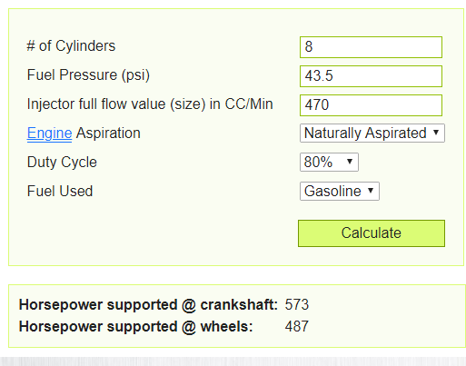
example on my corvette a 470cc in each runner port injector is approximately a 44 lb injector
vettinject.png


https://fuelinjectorclinic.com/flow-calculator


https://www.injectorrx.com/injector-size-calculator/

https://injector-rehab.com/shop/Injector-Flow-Conversion.html

https://fuelinjectorclinic.com/hp-calculator

https://www.witchhunter.com/injectorcalc1.php

http://www.wallaceracing.com/injector-sizing.php

http://www.raceworks.com.au/calculators/injector-hp-calculator/

http://www.rcfuelinjection.com/Technical

http://www.enginelabs.com/news/calculating-fuel-demands-and-injector-sizing-with-efi-university/

http://garage.grumpysperformance.com/index.php?threads/ideal-tpi-build.12203/#post-76070

related thread


heres a bit of advice! so many times I get called over to help in some project, only to find the problems the guys hoping I can solve could have been avoided entirely ,
if the guy whos at this point is going partially insane, had only bothered to carefully read the details or installation instructions.

many times youll see the guy ordered the wrong part number, and theres a very similar component that exactly matches the concept ,
hes currently waist deep into, only to find the component he ordered is not compatible with the rest of the parts, hes working with.
Ive seen guys order high impedance injectors that are installed on a controller designed for low impedance injectors

http://fuelinjectorclinic.com/faqs

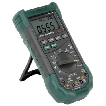
You can measure the resistance across the two electrical terminals of the injector. If the resistance is between 1.5 and 4.0 Ohm you have low impedance injectors. If the resistance is between 8 and 16 Ohm you have high impedance injectors.

https://www.hotrod.com/articles/hrdp-1211-low-impedance-vs-high-impedance-fuel-injectors/

Low impedance (peak and hold) injectors have a resistance of between 2 and 4 ohms. High impedance(saturated) injectors have a resistance of between 10 and 14 ohms. Low impedance and high impedance injectors cannot be used interchangeably without modification of the injector drivers.

What are the differences between low impedance/peak & hold and high impedance/saturated injectors?

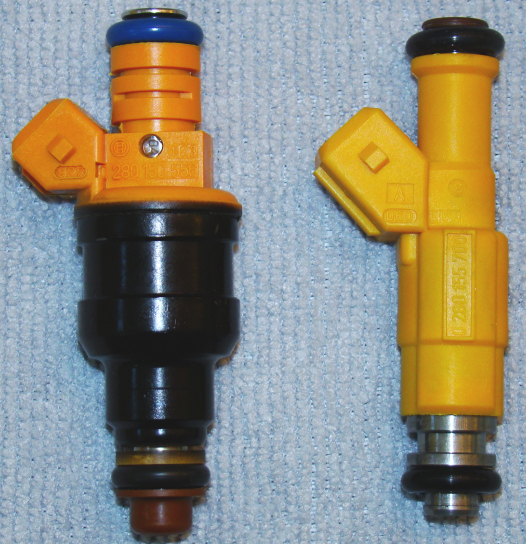
The older fat body style low impedance injectors (1.5 to 4.0 Ohm) used to have faster open and close times due to the type of electrical signal pattern emitted by an ECU equipped with proper P&H signal transmitters. This “Peak and Hold” injector signal typically uses a high (4 amp) initial current to open the injector, and which reduces to a lower (1 amp) current to keep the injector open until the pulse ends. Since this method put less total current into the coil, the coil heated up less and was therefore more reliable. Since the “hold” or lower current part of the signal has created a weaker magnetic field, the injector will also close more quickly.

High impedance injectors (10 to 16 Ohm) are triggered by a low (typically around 1.2 amps) constant current signal and kept open by the same constant (saturated) current for the entire cycle. Most OEM injectors today are high impedance injectors being driven by saturated injector signals from the ECU since car manufacturers are most interested in the simpler saturated signal which is more cost effective to produce when building ECU’s, especially where there is no apparent loss of drivability or performance.


https://www.summitracing.com/parts/...MIsMryyOf_3gIVjoTICh1o7wzhEAQYAiABEgKO9fD_BwE

https://www.summitracing.com/parts/...MInIGXief_3gIVy-DICh1rpgH3EAYYAiABEgJLafD_BwE

http://www.megamanual.com/v22manual/minj.htm

https://www.southbayfuelinjectors.com/fuel-injectors/high-performance

http://fuelinjectorclinic.com/hp-calculator

https://www.rceng.com/technical.aspx

finjk1.gif

finjk2.png

finjk3.gif

finjk4.gif


READ THROUGH THIS CLOSELY RELATED THREAD
AND SUB LINKED INFO
CAREFULLY

http://garage.grumpysperformance.com/index.php?threads/how-big-a-fuel-pump-do-you-need.1939/

http://www.fordracingparts.com/download ... FIComp.pdf


http://www.smartfireinjectors.com/fuelflowchart.html

http://www.smartfireinjectors.com/fuelflowchart.html

https://www.rceng.com/technical.aspx

https://www.holley.com/products/fuel_sy ... ts/522-831

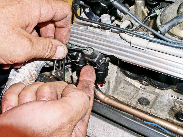
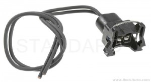
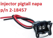
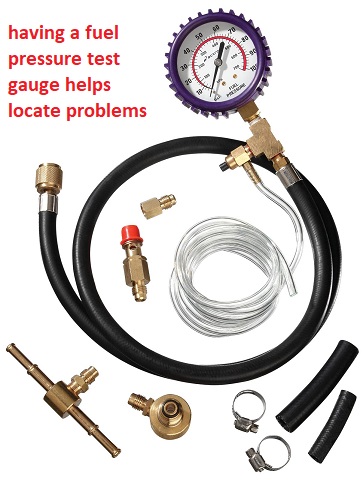
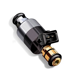
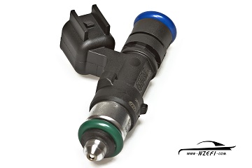
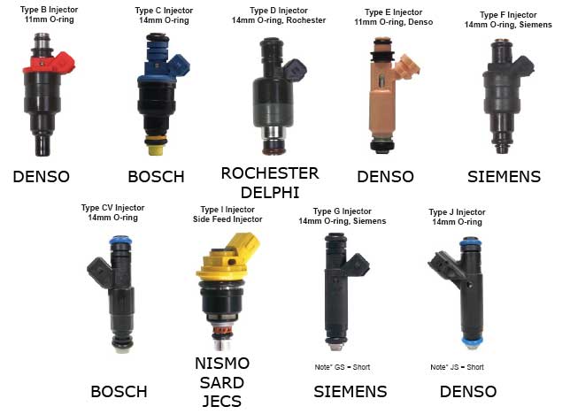
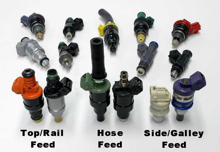
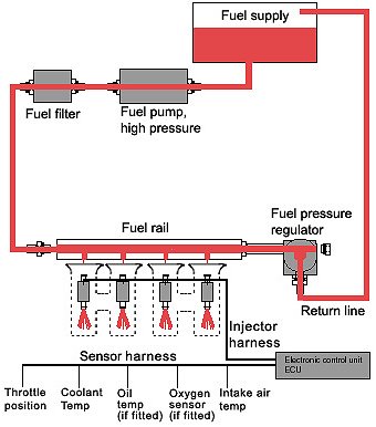
theres a good selection, of types, length, manufacturers, and mechanical types to select from, but obviously you need to calculate the correct size and know what fits your application.
keep in mind sensor input to the controling computer from MAT,MAP,MAF,HEAT , OXYGEN and other SENSORS have a HUGE effect on the injector effective flow rates.

calculate it yourself.
Max potential fuel flow is controlled by the injector size and design, and the pressure and voluum available in the fuel rails feeding the injectors

but
Effective FLOW

will rarely exceed 85% of the injectors RATED max and thats controlled in large extent by the pulse duration+sensor input values, the computer provides

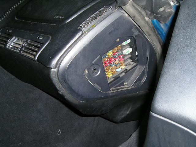
http://garage.grumpysperformance.co...lay-switch-locations-and-info.728/#post-43477

http://garage.grumpysperformance.com/index.php?threads/what-kills-o2-sensors.3049/#post-51701

http://garage.grumpysperformance.com/index.php?threads/testing-1985-89-m-a-f-sensor.1475/#post-43635


fui1a.jpg
fui2a.jpg
fui3a.jpg

fui4.jpg

fui5.jpg

fui6.gif

fui7.jpg

fui8.jpg

fui9.jpg

fui10.jpg


fuellinesizer.jpg

watch these videos


http://www.youtube.com/watch?v=l2ne6AVn ... re=related

http://www.youtube.com/watch?v=aIUJbTXN ... re=related

links

http://garage.grumpysperformance.co...at-manifold-air-temp-sensor.10349/#post-42530

http://garage.grumpysperformance.com/index.php?threads/testing-1985-89-m-a-f-sensor.1475/#post-43635

http://garage.grumpysperformance.co...lay-switch-locations-and-info.728/#post-25471


http://fuelinjectorconnection.com/shop/ ... ductid=202

http://www.witchhunter.com/injectorcalc1.php4

http://www.holley.com/TechService/Library.asp

http://www.scottsautorepair.net/viewtopic.php?f=10&t=33

http://www.injector.com/injectorselection.php

http://www.rceng.com/technical.aspx#Sel ... ctor_Size_

http://www.youtube.com/watch?v=7oTirEZN ... re=related

http://www.fuelinjectorconnection.com/s ... rcalc.html

http://www.youtube.com/watch?v=TMCrylOx ... re=related

http://www.witchhunter.com/injectorcalc1.php4

RELATED LINKS


http://www.rceng.com/technical.aspx

http://www.slowgt.com/Calc1.htm#FPHP

http://www.iroczone.com/calcs/injectorsize.htm

http://www.injectorsplus.com/

http://www.csgnetwork.com/fiflowcalc.html

http://www.bgsoflex.com/pwcomp.html

http://golenengineservice.com/calc/calcpchg.htm

http://www.ecs.fullerton.edu/~sowell/ja ... estRig.pdf

http://www.witchhunter.com/injectorcalc1.php4

http://users.erols.com/srweiss/calcpchg.htm

http://www.z31.com/software/injector.pl

http://www.solutions29.com/injcalc.htm

http://www.injectorrx.com/sizing.html


efisystem.jpg

Holley Injector Tech Said:

HIGH IMPEDANCE INJECTORS — Most injectors can be divided into two major categories: high impedance 12 to 16 Ohms and low impedance 1.2 to 4.0 Ohms. The high impedance injectors are used with ECUs that are designed with saturation drivers. The advantage of using saturation drivers is that the currents running through the ECU circuits and the injectors are relatively low thus generating less heat. The disadvantage of saturation drivers is that the driver has a slower response time, which could affect the full utilization of such a system at very high engine RPM.

LOW IMPEDANCE INJECTORS — The low impedance injectors are designed to be run with an ECU that employs peak and hold drivers (also called current sensing or current limiting drivers). The current ratio (peak to hold) is generally 4:1 and the most common drivers available are 4 amp peak/1 amp hold or 2 amp peak/ 0.5 amp hold. The peak current is generated to overcome the inertia of the closed valve and once the valve is open the driver cuts down to 1/4 of the peak current to hold the injector open until the end of the metering event. Low impedance injector designs are mostly used in high flow applications.

http://www.racetronix.biz/itemdesc.asp? ... 6x&eq=&Tp=

http://www.racetronix.biz/itemdesc.asp? ... 91&eq=&Tp=

http://www.racetronix.biz/items.asp?Cc= ... =1&Tp=&Bc=
STOCK TPI,LTI,LSI ENGINES USE HIGH IMPEDANCE INJECTORS —
LETS LOOK AT A DYNO SHEET FOR A BIT OF INFO

http://www.land-and-sea.com/dyno-tech-t ... g_bsfc.htm

http://www.carcraft.com/techarticles/re ... yno_sheet/

http://hotrodenginetech.com/engine-dyno-testing/

NOTICE THE BSFC and fuel/air ratio on this dyno sheet from a LS race engine that makes almost 900hp
427sbclsxdynoinfo222.jpg

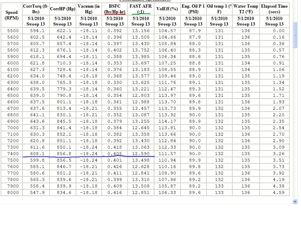
lets randomly select 7400 rpm
hes got 608 ft lbs of torque
/thats making about 857 horse power,
near the ideal 12.6:1 fuel air ratio,
.405 lbs of fuel per horse power per hour
a bit of math shows .405 lbs of fuel per hour x 857 hp=347 lbs of fuel per hour or 5.78 lbs per minute.
gas weights close to 6.1 lbs per gallon , so to make that 857 hp hes burning nearly a gallon per minute in fuel.
obviously he will need a fuel supply system that maintains that flow rate, plus a bit more at the injector fuel rail at 40 psi or higher
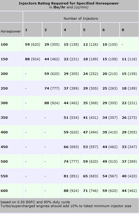
if we assume hes running at 75% of injector flow, so he has some safety margin built into the fuel delivery system, we see that 347 lbs of fuel per hour, delivered =347/75 x100=463 labs of fuel flow potential, divided by 8 injectors= a 58 lb minimum injector size, (60lb-64 lbs in an injector size selected,makes more sense)


read these links


http://fuelinjectorconnection.com/shop/ ... at&catId=2

viewtopic.php?f=55&t=2055&p=6026#p6026
 

Attachments

  • InjectorFlowRate.JPG
    InjectorFlowRate.JPG
    52.5 KB · Views: 7
Last edited by a moderator:
If your building a 475-525 hp street performance engine that most guys really want in their corvettes, the 36 lb rated injectors like Im currently running in my 383 should run fine but you'll have very little if any slack for further increased hp mods, the cpu will just cut pulse duration back a bit due to the higher flow rate on the larger injectors because of the o2 sensor input, will tell the cpu to maintain a set f/a ratio, or if you've got an adjustable fuel pressure regulator you can lower the fuel pressure a few pounds to reduce flow rates also, if the injectors a bit larger than ideal, the computer cuts pulse duration but it can,t increase pulse duration past the injectors flow rate , so keep that in mind

injectorsyu2.jpg

injectorsyu1.jpg

I frequently get guys telling me that some tuner told them to install a adjustable fuel pressure regulator to boost the engine power, that will work for marginal improvements in injector flow rates but it makes the fuel pump work harder and tends to reduce fuel pump life expectancy as it increased the heat the fuel pump generates,
the reason the suggested boosting the f/p is to increase the fuel mass injected,from the stock injectors, thats a band aid approach, the correct approach is to correctly alter the fuel map, to get a longer duration spray pulse from the fuel injectors and if the stock injectors can,t supply the required fuel in the upper rpm range youll need to increase the size rating on the fuel injectors you use, most fuel injectors are designed to operate at a max of 80% duration,if you install a 400hp-450hp engine youll need a minimum of 30lb-36 lb injectors, and 36lb-40 lb if you intend to exceed 470hp, I know its a p.i.t.a. but its amazing what works if its correctly tuned, and increasing the f/p to 58 psi is not the way to do it,you can,t fight facts and it takes (X) amount of fuel to make (Y) amount of HP if you want the f/a ratio to keep from burning pistons and detonation, I run 36 lb injectors in my 383 and it works just fine up to about 6000rpm where it starts leaning out slightly, I should swap to 42 lb injectors but I intend on swapping to a BBC soon so Im holding off.
I know you don,t want to hear it but stock injectors will not supply the required fuel to support the hp levels your intending to reach, if you want to use them in a 400hp plus engine,

calculate it yourself.
Max potential fuel flow is controlled by the injector size and design, and the pressure and voluum available in the fuel rails feeding the injectors
but
Effective FLOW
will rarely exceed 85% of the injectors RATED max and thats controlled in large extent by the pulse duration+sensor input values, the computer provides


http://www.injector.com/injectorselection.php

http://www.witchhunter.com/injectorcalc1.php4

http://forum.grumpysperformance.com/viewtopic.php?f=55&t=1200

BBCLucasMacKay1.jpg

BBCLucasMacKay3.jpg


its not a guessing game, its a simple calculation.
http://garage.grumpysperformance.com/index.php?threads/port-speeds-and-area.333/
use the calculators in this thread, posted above but keep in mind your looking at about 520hp PLUS flywheel if its dialed in correctly,, so you need to match the port cross sectional area, air flow rates and cam timing, and lift to the engines displacement and match the injector flow rates.
you need to maintain about a 12.5:1-12.8:1 fuel/air ratio at peak rpms to maximize your horsepower, and if the ports won,t flow enough air, or the cam restricts the ports with restricted duration or lift you won,t get the full potential power.
failure to match the components to the application will result in decreased performance.
Im going to upgrade to 42 lb on my 383 as soon as the budget allows.
being limited to the max injector flow can cause a lean condition that burns rings and gets you into detonation far faster than than having a slightly larger than ideal injector would do. don,t get crazy, use the calculators, but be a bit generous and don,t cut it too close, having a bit to much injectors like having a bit to much money, you don,t need to use its all, but like money, not having enough makes things difficult.

If youve got lets say a set of stock 24 lb injectors and your thinking that is the fuel pressure your confusing flow rate with fuel pressure
if youve got you've got 24 lb injectors, that FLOW 24 pounds of fuel per hour, at 100% flow or 100% duty cycle normally rated at about 43.5 psi, in an ideal world injectors operate at a max of about 80% duty cycle MOST of the time

read the info and play with the calculators in the linked info
youll quickly find that those 24 lb injectors are matched to the needs of an engine designed to produce a max of about 300-340hp, which is fine because they are factory matched to an engine that produces about that hp, and once you get much higher a larger injector is going to be a better match to your needs

viewtopic.php?f=55&t=2055&p=6026#p6026

keep in mind sticking killer heads that potentially flow 300 plus cfm on an engine, so you can produce impressive horsepower, then matching it to a restrictive exhaust or intake that won,t flow similar numbers or a cam that won,t open the valves far enough to get that full port flow, will significantly reduce your power , as will gearing the car so the engine can,t spend 80% or more of its time running in its most efficient power producing rpm band, you must maintain the fuel/air ratio and fill, and scavenge the cylinders efficiently, if you expect to produce good hp.....its all about matching the components in the combo to its intended use, then EFFICIENTLY filling, burning and scavenging as much fuel/air mix per, intake, power, and exhaust, stroke as you can manage.

you might find this chart helpful, notice the hp rating and injector sizes


http://www.holley.com/types/Marine%20Co ... 20Kits.asp


Injector swaps that INCREASE the flow rate by only a couple lbs will not be critical,because your cpu reads o2 sensor data to set the pulse duration on the injector, swapping from a 24 lb to a 26 lb has virtually zero effect on anything until the pulse duration must exceed 80% of the listed flow rate,to keep the fuel/air ratio at the 14.7:1 rate the systems designed to run at. simply because the cpu adjusts injector flow as required, by adjusting the pulse duration.
the advantage of the larger injector is that it can if required flow those two extra lbs of fuel.

http://forum.grumpysperformance.com/viewtopic.php?f=55&t=1200


o2grph.gif
 
Last edited by a moderator:
fuel pressure is a MEASURE of resistance to flow, get a gauge and measure the fuel pressure on the fuel rail shrader valve, if your not, getting pressure. its because theres little or no resistance to flow, or your pumps not running and pumping fuel or the fuel pressure regulators leaking,
your leak is or should be rather obvious, if the upper end of the injector leaks fuel out of the fuel rail, very obviously the upper injector o-ring thats been installed is either incorrectly assembled or the wrong o-rings were used
verify the fuel pressure with a fuel gauge connected to the shrader valve on your TPI fuel rails,
shrader1.jpg

]GM part number for the complete fuel rail o-ring kit is 17111696

http://tpiparts.net/tech_articles
heres a link to the correct o-rings they are light blue
NAPA sells them at times
fuel_injectorv.jpg

http://tpiparts.net/inc/sdetail/10950/300
Injector_O_Rings_ezr2.JPG

while the older injectors do tend to function with e85 fuel they are usually not truely compatible with ethanol and the o-rings may swell or slowly fail on the earlier c4 corvettes, it was not until the LS series engines were put into cars that true E85 compatible injectors and fuel line components were factory installed (1997) at the earliest.
fprpicq.jpg

if your TPI FUEL PRESSURE REGULATOR DIAPHRAGM LEAKS youll find it difficult or impossible to be starting your car


17113544 - Injector Seals
17111696 - O-Ring Kit
22514722 - Fuel Inlet O-Ring
22516256 - Fuel Inlet O-Ring


The above part numbers provided me with all of the seals shown below circled in red. I would recommend that you replace these seals whenever you service your TPI system. Remember, you've got gasoline under about 45 pounds of pressure flowing through the fuel rails etc. A leak could easily catch fire and cost you your car.

FPR_Diagram_zps62c51e7d.jpg


tpi-fuelrails.gif


tpidig1.gif


The front and rear crossover tubes use different size o-rings. Try a GP Sorenson 8009211 kit.

The o-rings on the feed/return lines are easily available through your local parts store too. GM parts # are 22514722 and 22516256. Borg-Warner 27478 or Niehoff 27478 are cross-references.

IF you want max performance youll need decent hood clearance,and direct port EFI, to allow intake runners with a direct path from throttle body to intake valve in a strait line

efit1.jpg

HERES A POST I SAW RECENTLY THAT COVERS SIMILAR INFO

SlowGTA said:
there are some things that have to be considered on a swap:

First you said you ran a steel fuel line? Better change that to stainless steel or you will start having problems with rust particles contaminating the fuel system. They plug filters and hang injectors open and cause general hate and discontent. The gas tank is another problem area if it's steel. Ethanol is hygroscopic meaning it attracts water. This water causes serious corrosion of steel. Ethanol also has corrosive effects on bare aluminum which can destroy it and cause the same particle problem. Stainless steel, some plastics(Teflon), and certain anodized aluminum are needed for the fuel system. Most fuel filters for performance alcohol use are intended for race engines with strict fuel quality control and use stainless steel mesh elements that only filter down to 100 microns. At least 40 microns is needed to stop all of the particles that can cause fuel system trouble. 5 or 10 microns would be better but I haven't found a high pressure, alcohol safe filter that filters that low yet. The best filter I've found is the Mallory 3181. It's a 40 micron alcohol compatible in-line filter for high pressure fuel injection that flows up to 500GPH.

Second it takes approximately 30% more fuel with E85 to make the same power as gasoline. You have to alter your fuel delivery accordingly. This also means that at the same power level your fuel tank will go empty way faster. This isn't a problem for some applications but can be for endurance racing where you don't have anymore room for fuel.

Third is that alcohol runs considerably cooler than gasoline and therefore needs more compression to make the same power as gasoline in a given engine. I'm not saying that an engine built to run on gas can't run ethanol, just that it won't make as much power as it could if it had more compression (or boost). The burn rates also require a complete ignition re-map to get power back up.

This barely scratches the surface of E85 for a performance engine, and I'm still learning as I go but I hope this helps..I think forced induction fuel injected engines would be a great place for this fuel to really make some power! I look forward to hearing your project shapes up.
 
Last edited by a moderator:
https://www.robietherobot.com/storm/fuelinjectorguide.htm

https://www.2carpros.com/articles/how-to-test-a-fuel-injector

https://www.chevyhardcore.com/tech-...-injector-identification-and-cross-reference/

 
Last edited:
basic fuel injector test
(pull your trouble codes and check battery voltage ,alternator output and ignition spark first)

(BTW it rarely hurts to drain old fuel thats over 4 months old and replace the cars fuel filter, then add two different brands of fuel injection cleaner and 6 oz of marvel mystery oil to as full tank of fresh high test gas to the car if its been sitting un-used for very long before you start testing for fuel injection related issues

now Ill assume your battery reads over 12 volts and the starter works, and easily spins the engine
the first step
find the fuel rail shrader valve and remove the cap and connect the fuel pressure gauge
if you turn on the ignition key to get the dash and accessories to light up but don,t start the engine,the fuel pump,
should briefly run to pressurize the fuel rail to about 38psi-42 psi,
this should stay at this pressure level for at least 5 minutes minimum, if it drops slowly your fuel rail is leaking fuel.
now the fuel pressure regulator may be defective or leaking, or in very rare cases the fuel pump may be defective ,
but the most likely cause is a fuel injector(s) stuck in the open position.
next pull the injector harness,
electrical_connectors.jpg

off a single injector at a time, press the wire bar to release the clip, retention, then pull it up and off, the noid light plugs into the harness,
use the spare injector pig tail
injectord3.jpg
injectorpt1.jpg

on the now disconnected injector ,connect the multi meter on ohms setting and it should read 11-13 ohms injector on each injector tested.
if it reads under 9 ohms or over 20 ohms its a defective injector
now use a couple 3 ft long test leads connect one too one of the pig tail test leads
https://www.walmart.com/ip/Uxcell-2...-Clips-Test-Jumper-Wire-1-5m-2-Color/45588242

testlkj.jpg

and to 12 volts, connect the other pig tail lead too a different test lead and watch the fuel pressure gauge,with the key out of the ignition , you should have 38-42 psi of fuel rail pressure, watch carefully while you tap the second test lead to ground (the plenum or alternator case works) the fuel pressure should drop as you tap the ground pig tail lead, this verifies the injector function at least partially, if you don,t see the pressure drop the injectors not allowing fuel flow through it and should be replaced.
after you complete each injector test , turn the ignition key on, to re-pressurize the fuel trail and reconnect the harness to the previously tested injector,
repeat the noid light and pig-tail function fuel pressure test on each of the other injectors individually.
Fusebox2.jpg

youll need a fuel pressure gauge and multi meter

image_6238.jpg

CP7838.jpg


it helps if you have a spare fuel injector pig-tail for testing
injectord3.jpg


having a NOID light injector harness tester wont hurt either
https://www.harborfreight.com/11-piece-noid-light-and-iac-tester-set-97959.html
205107_700x700.jpg

tpishrader.jpg


on the TPI and LT1 efi and many other EFI intakes,
theres a shrader valve,
that can be easily accessed to check fuel rail pressure,
dealing in facts you verify is always preferable.

fuelcirc1.png


Understanding Block Learn Multiplier (BLM)


Understanding Block Learn Multiplier (BLM)
David Huinker
Introduction
In a nutshell, the Block Learn Multiplier (BLM) is the long term fuel adjustment that the ECM "learns" to keep the air/fuel ratio within acceptable parameters. The Integrator is the same idea, only for short term adjustments. Basically, these two strategies are used to make adjustments and adaptations to the ever changing loads, atmospheric conditions, and fuel quality to keep the car's air/fuel ratio correct for driveability and emissions.
Also, keep in mind that when we say Long Term or Short Term, we are talking in computer time, not human time. In our ECM the Long Term fuel adjustment (BLM) happens about twice per second, while the Short Term fuel adjustment (INT) happens about 20 times per second
What are "Cells"?

The fuel delivery strategy uses a two dimensional table that has four rows and four columns, for a total of 16 "cells". Each cell contains a Block Learn Multiplier (BLM) value (from 0 to 255), which represents a long-term fuel correction based on that cell's operating conditions over a relatively long period of time. Each BLM value in turn contains an integrator value (also from 0 to 255), which is a short term fuel correction based on immediate operating conditions. For both the Integrator and BLM values, a higher value represents a correction that adds fuel to the fuel mixture, due to higher injector pulse widths.
MAF / RPM0-800 rpm800-1100 rpm1100-1500rpm1500 +rpm
0 – 9 GPSCell 0Cell 1Cell 2Cell 3
9 – 20 GPSCell 4Cell 5Cell 6Cell 7
20 – 30 GPSCell 8Cell 9Cell 10Cell 11
30 - + GPSCell 12Cell 13Cell 14Cell 15
The table above depicts the BLM cell table that is held in the typical Turbo Regal ECM. As you can see, it is offset by rpm in the columns, and by airflow in the rows. The individual cells are numbered 0 through 15 (for a total of 16 cells). So, the cell being accessed at any given point in time is controlled by airflow versus rpm.
Let's take a few "for instances". Let's say the car is sitting in the driveway in Park, up to temperature, and just idling. In that case:
  • RPM = 750
  • MAF = 6
Since the RPM is very low and the MAF is very low, the car will be using the information in BLM Cell 0 to adjust the idle fuel mixture. The value contained in that cell is adjusted with the Integrator values (which change based on O2 readings, etc.).
Now, let’s go for a typical highway cruise, at about 65mph, on a nice flat road:
  • RPM = 1800
  • MAF = 22
Since the RPM is above the highest value in the column to the right, and the MAF is reading a value in the “third” row, we can see that the ECM is now accessing, and using the BLM value in cell 11. Cruise conditions will often move between cells 7 and 11 based on small changes in MAF, since the typical highway cruise value is between 15 and 25.
Typically when you pull away from a stop sign or traffic light in fairly normal circumstances, you’ll see that it takes only a second or so for the RPM to jump over the 1500 upper RPM limit, and the MAF (air flow) will very easily jump up over the 30 gps upper MAF limit. In this example the ECM will be using cell 15 (sometimes erroneously called the WOT cell) (WOT meaning Wide Open Throttle).
OK, So what's the BLM DO?

The BLM is a long term adjustment , which is stored pretty much permanently (unless you disconnect power to the ECM), to the fuel delivery calibration that results from the ECM "learning" the values while you are driving around. 128 is the ideal value, because it is the center point of the range 0-255. Above 128, and the ECM is adding fuel to compensate for a lean condition at a particular load and RPM. Below 128, and it represents a correction for a rich condition.
How does the Integrator play into this?
On a cold start the INT is set to 128 and kept there until the coolant reaches a threshold value, a timer says the engine has been running long enough, and the O2 sensor has warmed up and started responding. The ECM then sets the closed loop flag, which meansthat if other conditions are met (not in PE, DE, or DEFCO modes, primarily) the ECM uses the O2 sensor to control the INT. It adds to the INT in small increments until the O2 voltage goes above a threshold so the ECM knows the engine is now rich, then it starts subtracting from the INT until the O2 voltage goes below another threshold and the engine is lean. The ECM keeps cycling the INT, trying to keep the time spent rich equal to the time spent lean so it knows that the average is stoichiometric. If other conditions are met then the learn control flag is set and the ECM keeps a moving average of the INT values. If this average is not 128, it will add or subtract to the current BLM value to move the INT average towards 128. This is done a few times a second, without the INT ever having to get to an extreme value such as 90 or 150. The stock BLM range is 105 to 150, but even if the BLM has reached one of these limits the ECM is still able to keep the engine averaging stoichiometric so long as the INT is not also at a limit. For example, the BLM could be 150 and the INT ranging between 135 and 145.
If you have a scan tool or Direct Scan you can watch this process. The ALDL update rate will keep you from seeing all of the INT values but you will still see the long-term trends. Start the engine and let it warm up so that learn mode is enabled, then pull the vacuum hose off of the fuel pressure regulator. The fuel pressure will jump up 4-7 psi and the engine will go rich. The INT will drop below 128 and go down until the engine finally goes lean or a limit is reached, and will then go up and down over a range of maybe 10-20 units as the ECM keeps the engine bouncing between rich and lean, and the BLM will start dropping. As it does, the average INT will rise back to 128. Once the INT average is 128 the BLM will stop changing. Put the vacuum hose back on, the fuel pressure will drop, the engine will go lean, and the mirror image of the above will occur. The INT will rise, start bouncing up and down, the BLM will rise, and the INT average will eventually reach 128 and the BLM will stop changing again.
Summary
BLM values are divided in to "Cells" based on MAF vs. RPM. Within each cell, there typically values from 105-150 for the BLM. Within the BLM value, there are Integrator values, typically 105-150 also.
The Integrator is adjusted based on sensor feedback (primarily the O2 sensor) to make real time adjustments for varying conditions. If the adjustments cannot be made in a BLM value, then the BLM value is either increased (add fuel) or decreased (subract fuel) to compensate.
If you reach the "corner" of an individual cell and not further adjustment is possible, the car may not run correctly and there is a problem with the calibration or a critical sensor.
It all sounds very intimidating, but really isn’t. One must keep in mind that the changes that are being made, as in the INT for example it is happening at close to 20 times per second. Think of it this way; The INT is used to “drive” the BLM number toward a value needed to maintain stoiceometric A/F ratio. As in one of the examples above, make a radical change (such as removing the fuel pressure regulator’s hose) and watch the INT do it’s thing!! The INT will jump to a high value, and hover there while the BLM starts its “march” up the scale. As the BLM approaches the value needed to get the A/F ratio corrected you’ll see the INT value heading back down toward 128. Ideally, they will both meet at 128 at about the same time. It’s really neat stuff to watch.


shaw2.png


GM part number for the complete fuel rail o-ring kit is 17111696

fprpicq.jpg

if your TPI FUEL PRESSURE REGULATOR DIAPHRAGM LEAKS youll find it difficult or impossible to be starting your car

heres a link to the correct o-rings they are light blue
NAPA sells them at times
all the o-rings on the fuel rails and injectors need to be dipped in thin oil so they insert and slide into place with less friction, this tends to greatly reduce the chance of the o-rings ripping, and yes you need the correct o-rings that fit correctly to begin with if you expect the rings to seal correctly
http://tpiparts.net/inc/sdetail/10950/300
Injector_O_Rings_ezr2.JPG


17113544 - Injector Seals
17111696 - O-Ring Kit
22514722 - Fuel Inlet O-Ring
22516256 - Fuel Inlet O-Ring
tpifp3.jpg

if you have a cylinder or two not functioning correctly or a injector thats barely functional, an infrared temp gun checking the exhaust port temps will generally allow you to find and isolate its location as it will be usually be running at a lower average temperature,
infrared thermometers are a very useful tool to track down issues with tuning, or mal functioning sensors , without verified facts your guessing.
this is the most consistently accurate I.R temp gun I've used for testing[/img]
42545.jpg

http://www.testequipmentdepot.com/e...1100200223789&utm_content=All Extech Products
INFRARED TEMP GUN

Wide temperature range from -58 to 1832°F (-50 to 1000°C)
any time that your dealing with a potential temperature issue or a trouble issue where , knowing the exact temperature vs what a gauge might say, it helps to have a handy and accurate infrared temp gun handy to locate and confirm heat, levels.

http://garage.grumpysperformance.co...dding-a-fuel-pressure-gauge.15264/#post-88472

http://garage.grumpysperformance.co...njection-at-start-up-problem.7309/#post-24862

http://garage.grumpysperformance.co...oven-facts-if-your-in-doubt.13051/#post-84695

http://garage.grumpysperformance.com/index.php?threads/tpi-fuel-pressure-issue.10385/#post-42943

http://garage.grumpysperformance.co...-system-trouble-shooting-flow-chart-info.596/

http://garage.grumpysperformance.com/index.php?threads/diagnoseing-tpi-lt1-problems.1241/

http://garage.grumpysperformance.com/index.php?threads/gm-tpi-stalling-diagnosis.15194/#post-86991
http://users.erols.com/srweiss/tableifc.htm
 
Last edited:
Back
Top