calculating engine volumetric efficiency

grumpyvette

Administrator
Staff member
you might want to spend some time learning the basics, so read the links below,
the most common mistake made by many people is that they fail to look at an engine as an interconnected group of component sub systems and they don,t realize that changes to a single component, no mater how much potential that component has is not going to allow that component or change in the potential to be realized until all the matched and supporting systems have similar potential.
EXAMPLE ,
the heads may be capable of flowing (x) on a stock engine but with careful selection of a cam with the correct duration and lift, and with a tuned header, and matching valve train mods along with some port and bowl clean-up the resulting improvements can be significantly more impressive.

http://garage.grumpysperformance.com/index.php?threads/is-backpressure-hurting-your-combo.495/

http://garage.grumpysperformance.co...alves-and-polishing-combustion-chambers.2630/

http://garage.grumpysperformance.co...e-springs-and-setting-up-the-valve-train.181/

http://garage.grumpysperformance.co...lsa-effects-your-compression-torque-dcr.1070/

http://garage.grumpysperformance.com/index.php?threads/more-port-flow-related-info.322/

http://garage.grumpysperformance.co...2-bbc-rebuild-but-think-things-through.13604/

http://garage.grumpysperformance.co...t-intake-on-oval-port-heads.13146/#post-69975

http://garage.grumpysperformance.com/index.php?threads/calculating-ideal-port-size.624/

http://garage.grumpysperformance.com/index.php?threads/carb-intake-manifold-engine-flow-rates.10194/

http://documents.holley.com/techlibrary_selecting_a_carburetor.pdf

http://www.wallaceracing.com/intakecfm.php

Volumetric Efficiency

Actual CFM


= Volumetric Efficiency

Theoretical CFM

viewtopic.php?f=55&t=2994&p=32443&hilit=carb+restrictive#p32443

http://www.hipermath.com/engines/carburetor_cfm

http://www.enginebasics.com/Advanced%20 ... ooler.html

http://www.summitracing.com/expertadvic ... Calculator

http://gottafishcarburetors.com/CFM Formula.html

http://wallaceracing.com/intakecfm.php

Volumetic Efficiency or VE, I will be using from this point, varies depending on temperature and pressure.

From that, we know a normally aspirited engine will have VE of 100% or less. And force inductioned engine will have VE of 100% or more.

The actual calculation of VE is done by ECU using measured amount of intake air, with Mass Air Sensor measuring at intake pipe or Speed Density measuring inside the intake manifold (close to intake port of the engine).

Theoretical CFM

theoretical cfm = rpm x displacement / 3456

Engine Flow Demand

Engine Flow= (engine displacement) X (volumetric efficiency) X (engine speed) X (manifold pressure)

You can see the key to increase engine flow is to increase engine VE (volumetric efficiency). Reduce intake charge temperature is the easiest way to help increase engine VE. This is where air/air, air/fluid intercooler and water injection come into play.
Engine Flow Measurement

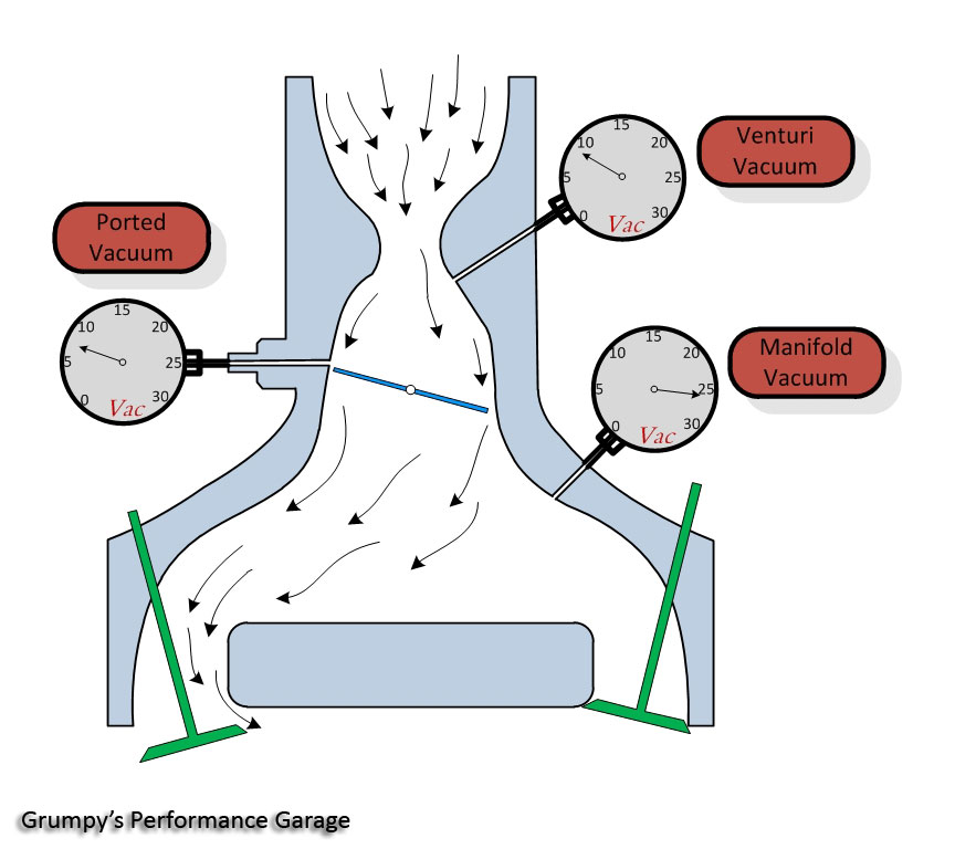
Most engine control systems in production today utilize either speed-density sensors or air-mass sensors to measure engine air flow. Speed-density is very popular because of its low cost and high reliability. Speed-density systems typically calculate engine flow rate based on engine speed, intake manifold pressure and temperature. Some systems use barometric pressure sensors and inlet air temperature sensors to improve flow calculation accuracy for varying ambient conditions. Fig. 1 illustrates a typical engine with both speed-density sensors and an air-mass sensor.
read these related links

http://tunertools.com/articles/volumetr ... ciency.asp

http://www.ajdesigner.com/phpengine/eng ... ciency.php

http://www.installuniversity.com/instal ... 012000.htm

http://www.epi-eng.com/piston_engine_te ... ciency.htm

http://www.ztechz.net/id2.html

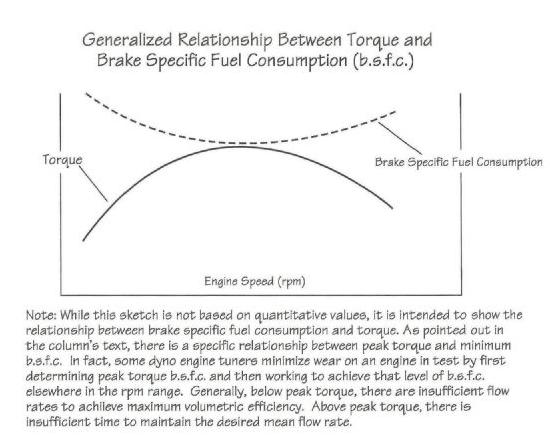
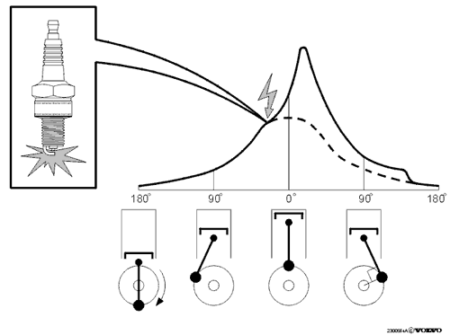
an engines Torque peak is almost always very closely related to the point in the rpm curve where the most effective/efficient cylinder fill, cylinder fill is related to both intake port cross sectional area and exhaust scavenging,efficiency, and is limited by port stall, and cam duration in relation to displacement, compression and valve train stability, ...all factors are easily calculated
links below

volumetric.gif


useful RELATED INFO you might want to read

http://www.wallaceracing.com/runnertorquecalc.php

http://www.pontiacracing.net/js_header_length1.htm

http://www.superchevy.com/how-to/en...-0902-chevy-engine-port-variations-measuring/

http://garage.grumpysperformance.com/index.php?threads/port-speeds-and-area.333/

http://garage.grumpysperformance.com/index.php?threads/calculating-ideal-port-size.624/

http://garage.grumpysperformance.com/index.php?threads/sellecting-cylinder-heads.796/

http://garage.grumpysperformance.co...ting-a-port-size-and-intake-for-nitrous.4930/

http://garage.grumpysperformance.com/index.php?threads/semi-fool-proof-cam-sellection.82/

http://garage.grumpysperformance.co...velocity-heads-tuned-intake-turbulence.12998/

http://garage.grumpysperformance.com/index.php?threads/calculating-header-design.185/
 
Last edited by a moderator:

I've seen this question in another forum......where does the 3456 come from???

In many equations there will a value that converts units so that we are comparing apples to apples. The equation for
VE has above the line "Cubic Feet/Min" (CFM) and below the line is "Cubic Inches Displacement" (CID). The 3456
converts the CFM to CuIn and compensates for the Intake stroke happening every other revolution.


Attachments

  • CubicInchesToCubicFeet01.jpg
    CubicInchesToCubicFeet01.jpg
    26.3 KB · Views: 157
Hey Grumpy,
Is the CFM on the top half of the equation the cfm that the heads flow?
 
busterrm said:
Hey Grumpy,
Is the CFM on the top half of the equation the cfm that the heads flow?

no its the total CFM the engine flows measured at the throttle body or carburetor inlet

but remember cam timing,head flow and exhaust scavenging and other factors effect results
http://www.csgnetwork.com/cfmcalc.html
volumetric.gif

volumetricz.jpg


THINK THROUGH YOUR OPTIONS AND THE COMPLETE COMBO,
I see guys have long discussions about things like the difference in port cross sectional area or the best connecting rod length, to use, no one factor is going to make your engine totally dominate the competition, its a combo of small almost insignificant individual component choices being made and a good deal of time and effort taken during the assembly and clearancing work, that stack up to give you or prevent you from maximizing the engines performance.
you may not even think about factors like polishing crank journals, or valve train geometry or intake runner cross sectioinal area or length ,or intake runner port matching or surface finish, but the combined effects of your choices and components selected do mater!
look guys I think a good deal of this discussion is missing the point here, Ive built well over 150 engines in the last 45 years, (I lost cound decades ago)
but I can assure you that longer rods and the easily verifyable slight increase in dwell time, the longer rods produce will be totally meaningless UNLESS, you design the engine for and select components too take full advantage of the minor increase, by carefully calculating the REQUIRED compression ratio,fuel octane required,all the factors related to the cam timing,(duration,lift, LCA) you calculate and build and install, and tune the engine for , a matched exhaust header scavenging (header primairy length and diameter plus collector design) and the intake runner length and cross sectional area, to maximize the cylinder scavenging effects, plus you match the fuel/air ratio, and ignition advance curve, to maximize that longer dwell times potential advantage.
 
Last edited by a moderator:
it will be close to correct, but depending on several factors your engine could run almost anywhere between about 75% and 105% efficient, but don,t get nuts, just select a carb thats easy to adjust and tune and on street cars a vacuum secondary carb will self regulate flow to the engines needs, on most sbc engine cars under 410 cubic inches a 650cfm-750cfm vacuum secondary holley can be tuned to work great, on most big blocks 454 or larger I jump to a 850-950cfm, Ive always found holley carbs about the easiest to tune and having the carb just a bit larger than the formula suggests seldom hurts, a skilled tuner can get a carb thats a bit to large to still run decent and carb spacers can be used to allow the engine to breath better with a carb thats a bit restrictive
remember that carb flow rates are calculated at 1.5" of vacuum using mercury not water and if you use dual or multiple carbs you reduce the vacuum signal considerably that each carb sees, a dual quad setup that has two carbs rated at 600 cfm each might only flow 380cfm each operating in tandem , not the 1200c fm you might expect

RELATED INFO

http://garage.grumpysperformance.co...ir-ratios-that-gets-ignored.15506/#post-92064


viewtopic.php?f=55&t=109

viewtopic.php?f=55&t=211

viewtopic.php?f=55&t=1038

viewtopic.php?f=55&t=5229

viewtopic.php?f=55&t=1639

viewtopic.php?f=55&t=1790

viewtopic.php?f=55&t=5510

viewtopic.php?f=55&t=58
 
Last edited by a moderator:
Okay, it just threw me when Indycars posted your formula for VE, the cfm had me scratching my head. Its just that we are figuring to get a good carb size and that formula is asking for a size of which are in search as it is. I was just thinking that the cfm in that formula was another measurement.

So is it suggested to maybe run a spacer on a air gap intake? Just curious, will it help when your carb is a bit larger than it should be on a air gap intake?

I read a lot of the info in the links, so when the carb is elevated it gives a smoother path to the cylinders of the air/fuel mixture. When the mixture hits the bottom of the intake runner it breaks up the mixture before it is able to fill the cylinder?
 
"grumpy I played with several calculators and they all suggest a 650cfm carburetor size is about ideal on my 350 Chevy, yet I put a old 850 cfm holley I had on the engine and it runs great, just for giggles I temporarily swapped carbs with with a friend who has a 650 and while it took some tuning the car ran about the same, once dialed in, so why bother with those calculators they don,t seem to matter?"


the calculators give you a starting point , and on most engines they work reasonably well to get you in the ballpark on carb size , but almost any 350-400 sbc can be tuned to run extremely well with most 600cfm-850cfm carbs, cfm rating is not nearly a critical as the ability to tune the combo correctly,simply because as vacuum levels under the carb base increase the carb flows more air and if you use a vacuum secondary the carburetor air flow adjusted as required , but that being said a 750 vacuum secondary carb usually makes tuning a performance engine fairly easy


most 4 barrel carbs are rated at 1.5" of vacuum

http://users.erols.com/srweiss/calcdchg.htm
PLAY WITH THE CALCULATOR AND YOULL SEE WHAT IN MEAN

viewtopic.php?f=44&t=773

viewtopic.php?f=55&t=109
 
remember that carb flow rates are calculated at 1.5" of vacuum using mercury not water and if you use dual or multiple carbs you reduce the vacuum signal considerably that each carb sees, a dual quad setup that has two carbs rated at 600 cfm each might only flow 380cfm each operating in tandem , not the 1200c fm you might expect
Please excuse my ignorance of multi carbs, but I was hoping for some clarification on this. I would assume in the example, it's a function of the engine only being capable of pumping 760 cfm thus limiting the flow of the 2ea 600s. Or is this just a function of diminishing returns by inherent inefficiencies of carberation?

Is there a different cfm calculation for multi carb or is it kind of a trial and error from observed readings (which vary from engine, cam, venturi sizes, and rpm that additional carbs are brought in etc...). I read through the links, but didn't see any more on the diminished flow from low vacuum on multi carb setups.

I ask because I may be way off, but I was under the impression that cfm was just cumulative. How ever many carbs it took to hit the magic number was what it took. Just get as close as you can, if not (in two extreme cases) that too much cfm = slow throttle response; too much air and it would have a tendency to run lean. Not enough cfm = less than max effort due to lack of air and fuel; too small of a venturi area would cause the air speed to try and ice the carb much like a pneumatic tool.
 
Last edited:
ok, remember outside air pressure at sea level is at or close too

http://airdensityonline.com/

http://www.can-of-whoopass.com/index.php?pageID=car_stuff&calculator=carb_size

http://garage.grumpysperformance.co...tte-shows-a-trouble-code-33.15594/#post-93198
Pressure26.gif

that outside atmospheric air pressure at a given altitude will remain semi consistent, above the carburetor inlets
your engine will have a set compression ratio and displacement.
lets say you build a 383 sbc, in theory you can spin that engine to about 6400rpm with commonly available parts rather easily (more RPM,obviously with higher strength and more expensive parts)
but assuming a displacement of 383 cid spinning at 6400rpm , thats 709 cfm at 100% efficiency, lets assume each carbs venturie is .750" that would equal .442 square inches x
12=about 5.3 square inches(obviously youll want to measure and get the correct figures to work with) and get the plenum vacuum at each 500 rpm or so.
the reduced flow rates per carb do not necessarily reduce the power, in fact if correctly tuned the multi point fuel distribution generally helps even out the fuel distribution.
and at any set rpm you can generally take a plenum vacuum reading and get a fairly consistent reading.

vgauge.gif

http://www.harborfreight.com/fuel-pump-and-vacuum-tester-93547.html

VenturiVacuum01.jpg

https://en.wikipedia.org/wiki/Manifold_vacuum
Manifold vacuum, or engine vacuum in an internal combustion engine is the difference in air pressure between the engine's intake manifold and Earth's atmosphere.

Manifold vacuum is an effect of a piston's movement on the induction stroke and the choked flow through a throttle in the intake manifold of an engine. It is a measure of the amount of restriction of airflow through the engine, and hence of the unused power capacity in the engine.
In engines that use carburetors, the venturi vacuum is approximately proportional to the total mass flow through the engine (and hence the total power output). As ambient pressure (altitude, weather) or temperature change, the carburetor may need to be adjusted to maintain this relationship.
http://www.linnbenton.edu/auto/perform/vacuum.html
http://users.erols.com/srweiss/calcdchg.htm
http://www.musclecardiy.com/performance/induction-math-high-performance-engines/
if you double the cross sectional area of the carburetor venturies feeding the engine you've effectively cut the air flow velocity through each venturie in half , with each of those six two barrel carbs working in stages to open your effectively allowing 12 very small venturies to supply the engines plenum, if you measure each carbs venturie cross sectional area you can calculate the starting and potential wide open throttle cross sectional area, and take a plenum vacuum reading at every 500 rpm or so, and calculate rather easily what each carbs actual contribution to the plenum air flow is.


http://users.erols.com/srweiss/calcdchg.htm
a carb flows less if the plenum vacuum is less

ignitiontiming.png

Stoich.gif


http://www.musclecardiy.com/performance/induction-math-high-performance-engines/
Engine Air Capacity
We can’t make a cylinder hold more than its physical dimensions, but we can increase the density of the gas captured within it. Hence the terms air capacity, volumetric efficiency, and inertial ram tuning. The earth’s atmosphere does us the courtesy of providing 14.7 psi of pressure to fill the cylinders for free. In a perfect world, the engine would inhale the exact swept volume of all its cylinders every two revolutions of the crankshaft. That represents its theoretical or potential air capacity. The following formula is used to calculate it.

Air Capacitycfm = (displacement x RPM) ÷ (1,728 x 2)

Note that air capacity is a function of displacement (volumetric capacity) and engine speed (RPM). The displacement is divided by 1,728 (the number of cubic inches in a cubic foot) to convert it to cubic feet. The RPM is divided by 2 because the engine only intakes on every other revolution. The formula can be simplified as follows:

Air Capacitycfm = (displacement x RPM) ÷ 3,456

In practice this formula is often useful to calculate the engine air requirement at both peak torque and peak power. Why? Because we want to know the minimum requirement at peak torque or the point of highest efficiency. Then we want to establish the maximum requirement at peak power so we can determine the effective airflow range of the engine under wide open throttle (WOT) conditions.

Let’s calculate the airflow requirement for a 350-ci engine with a torque peak at 5,300 rpm and a maximum engine speed of 6,500 rpm. First the torque peak:

CFM = (350 x 5,300) ÷ 3,456 = 536 cfm at the torque peak
And then the power peak:

CFM = (350 x 6,500) ÷ 3,456 = 658 cfm at the power peak These are the engine’s theoretical air requirements if we didn’t have all sorts of interference and restriction from carburetor venturis and throttle plates, manifold runners, intake ports, valves, and so on.

yeah! theres long bloody fingernail marks on the pavement showing where I was reluctantly being drug kicking and screaming all the way into the computer age... this was what I was REQUIRED too use in college when I went through engineering classes
versa2.jpg


now I carry a more modern version, so yeah over time I learn too adapt.
tx83plus.jpg


Volumetric Efficiency
In the preceding example the theoretical airflow capacity requires at least 536 cfm at the torque peak and 658 cfm at the maximum engine speed. These would be airflow requirements at WOT. So we need a 650-cfm carburetor, right? Not so fast. Many factors combine to reduce or in some cases increase the actual airflow requirement.

Volumetric efficiency is the volume of air the engine is theoretically capable of ingesting (potential) versus the actual volume that makes it into the cylinder, all other factors considered. In effect, it is the difference between the mass of the charge consumed by the cylinders and the mass of an equal volume at atmospheric pressure at any given RPM. It is affected by carburetor or throttle body size restrictions, engine speed, air temperature, manifold and port restrictions, valve size, chamber shrouding, camshaft overlap, and pumping losses.

Airflow measured on a running engine divided by the potential or theoretical air capacity at any given RPM is the engine’s actual volumetric efficiency at that particular engine speed. While not perfectly linear, it is sufficient for calculating volumetric efficiency. The following formula yields the percentage of volumetric efficiency:

VE % = (measured CFM ÷ potential CFM) x 100

If our 350-ci sample engine is a street engine and we are able to measure airflow on a dyno we might find that the actual airflow at 5,300 rpm is only 450 cfm and rising to 539 cfm at the maximum engine speed of 6,500 rpm. This would yield volumetric efficiency calculated as follows:

VE % = (450 ÷ 536) x 100 = 84% at the torque peak
VE % = (539 ÷ 658) x 100 = 81.9% at maximum engine speed
of dyno pulls and extensive research have established typical VE percentages for most engines. Standard passenger cars are generally 70- to 80-percent efficient, while high performance engines range from the low 80s to the mid 90s. Tuned racing engines routinely exceed 100-percent volumetric efficiency because their high-flow cylinder heads, tuned intake systems, cam timing, and exhaust scavenging provide exceptional efficiency. Highly refined Pro Stock drag racing engines are capable of achieving up to 125-percent VE. That means that the actual charge in the cylinder is 25 percent denser than the same volume before it enters the engine. Combined with ultra-high compression ratios, it really packs some power in the form of mean effective pressure.

At 85-percent VE, a 350-ci street engine only consumes 297.5 ci of air by volume. The only way to change it is to supercharge it or increase the efficiency of cylinder filling by applying the right combination of naturally aspirated components. In a naturally aspirated engine the goal is to increase the inertia of the incoming charge and reduce the restrictions it has to navigate on its way to the cylinder. A good system accomplishes this with a mean port speed of about 240 ft/sec. The important thing to remember is that low restriction and high charge inertia are achievable through proper carburetor or throttle body sizing, appropriate manifolding and cylinder head port volumes that match engine displacement and anticipated RPM.


Power and Volumetric Efficiency
The cornerstone of power building is volumetric efficiency (VE). The more air an engine is able to process, the greater its power potential. Volumetric efficiency is determined according to an engine’s static air capacity or displacement. A displacement of 400 ci represents 100 percent air capacity for an engine of that particular size. At any given engine speed a percentage of that volume is being processed into torque, depending on a host of variables that conspire to limit airflow. Without these pesky restrictions, atmospheric pressure can easily fill the cylinders 100 percent every two crankshaft revolutions. In practice, this is difficult to achieve because airflow is restricted by a throttling device (carburetor, throttle body, or other), imperfect intake manifolding, intake ports, valves, and all the attending flow restrictions and pressure dynamics present in a running engine. Hence, VE in a production engine rarely exceeds 70 to 80 percent.

As previously noted, VE is reduced below the torque peak due mainly to insufficient airflow and poor mixture quality. Above the torque peak, VE is limited by inadequate time to fill the cylinder due to RPM. One of the successful engine builder’s primary goals is to exceed the static air capacity of the engine and optimize combustion efficiency once fuel is introduced to the process. Savvy engine builders skillfully manipulate the component composition to accomplish this—broadening the torque curve and positioning it to best suit the intended application.

In specifying components to meet VE requirements, builders target intake ports, dimensional qualities of intake manifolds and exhaust headers, carburetor size, rod-to-stroke ratios, valve timing, and static compression ratio. The specific component matrix is adjusted to suit the application’s operational requirements. Ovaltrack and road-racing engines typically call for a component mix producing a broad torque curve over a wide range of RPM. This affords the engine builder an opportunity to tune the intake and exhaust systems separately to effectively broaden the power band. Conversely, drag racing applications seek a higher and narrower power band in which intake and exhaust tuning are more closely aligned.

Identifying and targeting the required power band is one of the engine builder’s first steps. Since VE and engine speed are closely aligned, it is critical to target VE modifications to the desired engine speed. If a drag racing engine leaves the starting line at 7,000 rpm and cycles between there and 9,000 rpm through the gears, its VE at 5,000 rpm is largely irrelevant. And, of course, an engine delivering power between 4,500 rpm and 7,200 rpm will need broader tuning efficiency from its parts combination. Hence, airflow management within the targeted engine speed range becomes a central challenge in matching or exceeding an engine’s potential VE capacity.
Intake Manifolds
Intake manifold and carburetor restrictions are prevalent in many types of racing. They are primarily intended to limit airflow and RPM potential. In some cases more than one choice is offered and the final selection is based on which configuration generates the best VE and torque tuning potential. That’s why, where rules permit, a twincarb high-RPM tunnel ram is chosen over a single 4-barrel for a drag racing application, but you’re not likely to see a tunnel-ram intake on a road racing car. Some classes dictate the use of a dual-plane intake, which often extends to the use of a stock cast-iron manifold. When the intake manifold is specified, all you can do is identify the manifold’s characteristics and tailor your package accordingly.

We’ll also discuss how to map manifold characteristics on a flow bench to obtain a ballpark view of individual port strengths and weaknesses. Once you have a clear picture of the manifold’s efficiency you can evaluate potential steps to ensure its contribution to maximum performance. Depending on other restrictions, these may include rocker ratio or cam timing adjustments to individual cylinders based on individual runner flow dynamics. Or it may be addressed by manipulation of header dimensions to complement and possibly broaden the torque range dictated by the intake manifold’s fixed dimensions. If allowed, carb spacers may support better mixture quality and, in the case of dual-plane intakes, staggering jetting from side to side may also provide some improvement particularly as it relates to the lean side of the engine. Many circle track classes also require a 2-barrel carburetor of a specified size with no modifications allowed, although repositioning of the carburetor location on the intake manifold is sometimes permitted.

Street Carburetor vs Race Carburetor
Engine air capacity and VE are important to carburetor selection because most carburetor functions are initiated and controlled by airspeed through the venturis and boosters. Once you establish the engine’s airflow capacity using the CFM formula, you need to multiply it by the appropriate percentage to account for VE losses. Street Carburetors The general rule for performance street engines is 85 percent of the theoretical or potential air capacity. Carb Sizecfm = [(displacement x RPM) ÷ 3,456] x 0.85 Recalling our theoretical 350-ci engine, we can calculate the cfm requirement at maximum engine speed: CFM = [(350 x 6,500) ÷ 3456] x 0.85 = 559.5


3171.jpg

Carburetor venturi size also affects carburetor airflow capacity. Compare the 11⁄4-inch primary venturis on this 390-cfm Holley carburetor to the 13⁄8-inch primaries on a 750-cfm Holley HP 4-barrel. Note the degree of restriction caused by the smaller venturis on the 390 version. (Courtesy Holley)


415.jpg

This Dominator is plenty of carburetor for a hot big-block engine, but it would perform poorly on most small-blocks except perhaps larger strokers such as World Products 454-ci small-block Chevy. (Courtesy Holley)
Race Carburetors
The general rule for racing carburetors is to have 1.1 times the calculated air demand because VE is usually greater than 100 percent. To accommodate the higher efficiency, multiply the theoretical air potential by 1.1. So if our 350 engine is highly modified with racing heads, cam, and intake manifold, we calculate as follows:
Race Carbcfm = [(350 x 6,500) ÷ 3,456] x 1.1 = 724

In this case, you would probably choose a 750-cfm carburetor since it is the nearest common size, especially if you are drag racing. If you are road racing, you might consider a 700-cfm Holley because it has 1/16-inch-smaller venturis that might improve throttle response off of tight corners. In this case the smaller carb may prove to be the better choice. As a general rule, it has been found that going with the smaller carb almost always yields the best results.

Performance carburetors are mostly made in 50-cfm increments, so if your airflow calculations happen to split the difference, choose the smaller carb unless you have a compelling reason to go larger. Supercharger and turbocharger applications present a higher air demand to handle the increased airflow capacity of the supercharging device. (See “Boost and Supercharger Drive Ratios” on page 72.)

Choosing Throttle Body Size
Throttle body equivalents pretty much parallel carburetor sizing because the engine’s airflow requirement is unchanged. In most throttle body applications the air is not burdened with the task of carrying fuel to the valve, but it still needs to maintain sufficient energy (velocity) to support efficient cylinder filling. To calculate an equivalent throttle body size based on known carburetor size, you need to recall the formula for the area of a circle:

A = diameter2 x 0.7854
Or, in this case:
A = diameter2 x 0.7854 x number of throttle bores

You can use this formula to calculate the throttle bore area of a given carburetor and compare it to an equivalent throttle body. You can calculate the area of a large single throttle body or the combined area of a multiple bore throttle body. Calculate the separate areas and multiply by the number of bores in the carburetor or throttle body.


615.jpg

Two appropriately sized Holley 4-barrels ensure an adequate supply of air when the supercharger ramps up its air demand. (Courtesy Holley)

Here’s an example with a 750 Holley carburetor that has four throttle bores measuring 17⁄16 inches compared to a single-bore 75-mm aftermarket throttle body for a fuel injected application:

First, find the total throttle area of the Holley.
Convert to decimals.
17⁄16 = 1.4375 inch
Find the area.
A = 1.43752 x 0.7854 x 4 = 6.49 square inches
Calculate the area of the 75-mm throttle body.
First convert to inches (multiply 75 mm by the conversion factor 0.0393701).
75 mm x 0.0393701 = 2.9527 inches (equivalent diameter)
Now calculate the area of the 2.9527-inch-diameter throttle bore.
2.95272 x 0.7854 = 6.84 square inches

Recall that the 750 cfm Holley had 6.94 square inches of throttle area, so the 75-mm throttle body is a little larger. To calculate an exact throttle body equivalent use a shortcut by working in percentages. It will get you very close.

6.49 (Holley) ÷ 6.84 (throttle body) = 94.8%
75 mm x 0.94 = 70.5 mm
A 70- or 72-mm throttle body would be the closest equivalent for your application.
 
Last edited:
Back
Top