"
HEY GRUMPYVETTE?
I picked up a tall deck,Chevy big block 427, block, at a yard sale and a friend donated a set of 454 .060 pistons
Ive got several intakes for big block engines ,both oval and rectangular port, styles, whats it going to take to build a 496 stroker from these components?"
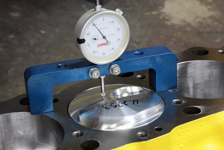
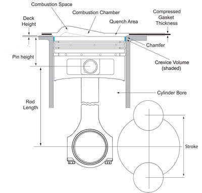
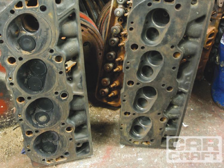
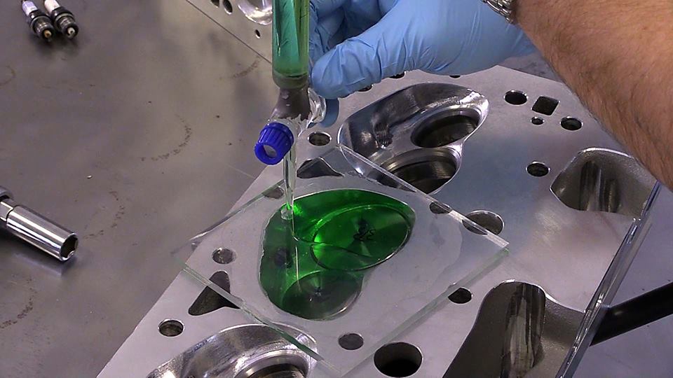
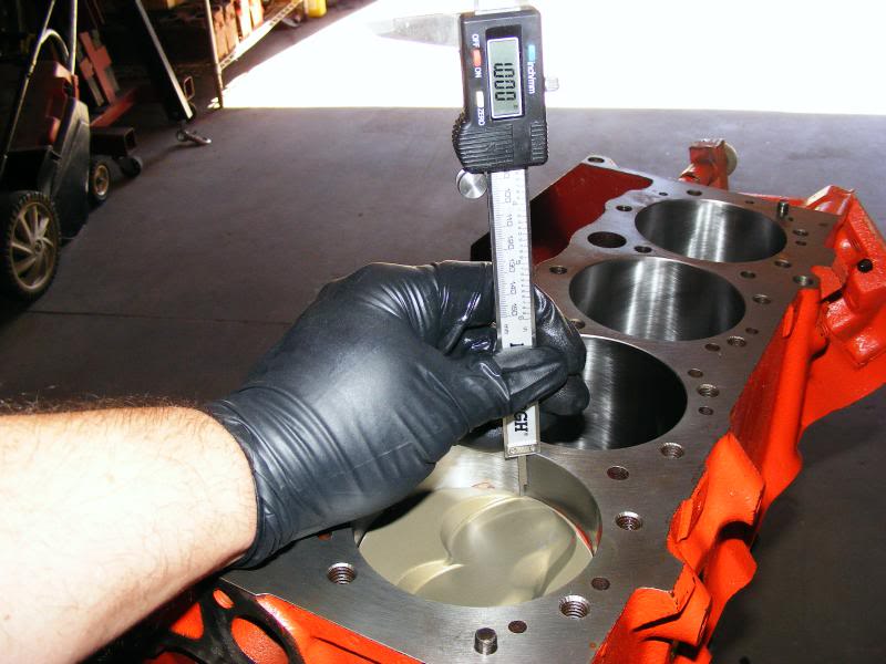
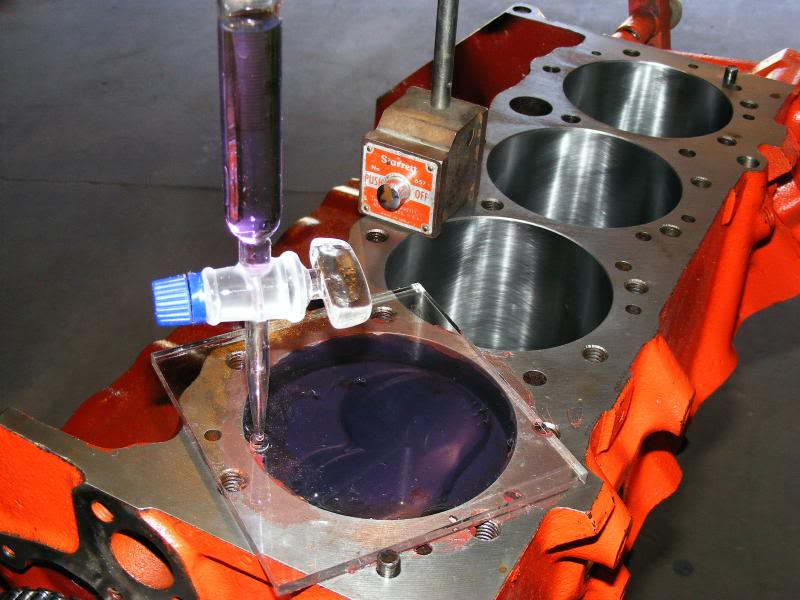
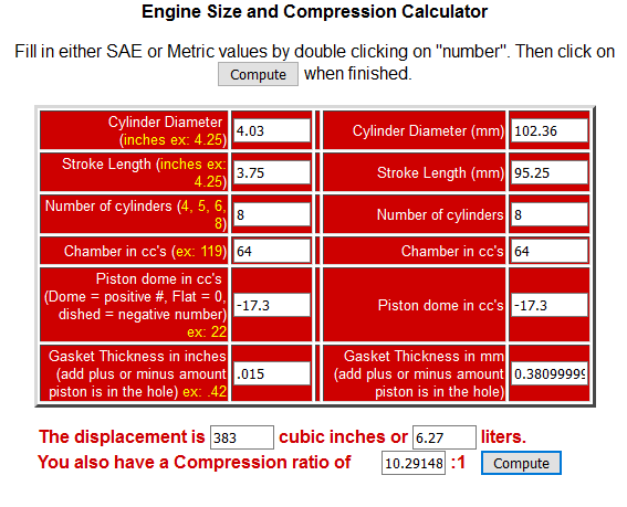
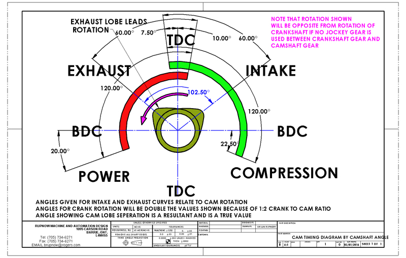
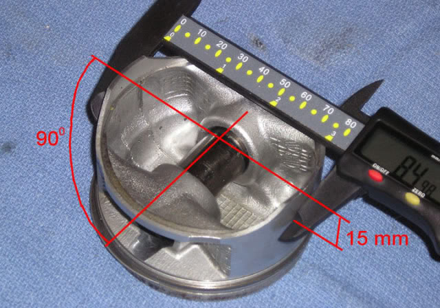
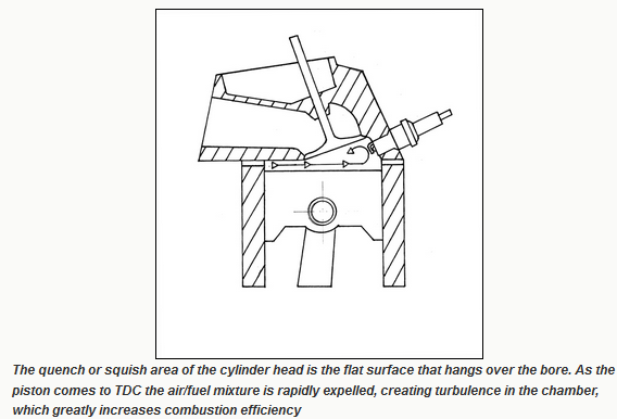
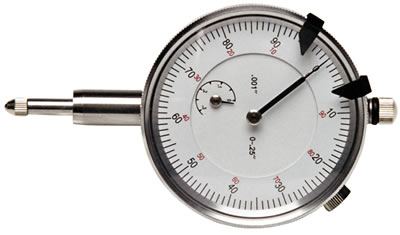
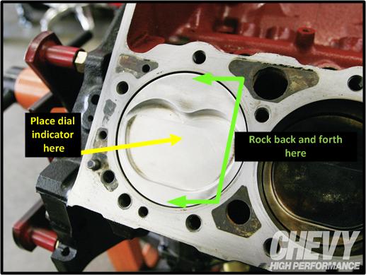
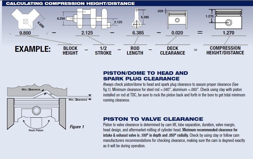
it should be rather obvious that youll need to know the exact distance the piston deck sits at TDC ,above or below the block deck surface and the valve notch recess or pop-up dome volume of the piston to do accurate quench or compression calculations
if you find the rotating assembly is more difficult to rotate than you expected, you may want to verify some clearance issues that get over looked at times,
theres also some, other potential issues,
theres a slight potential for the piston wrist pins too not rotate effortlessly in the piston pin bores ,
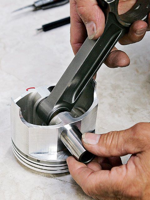
that may add to the difficulty in rotating the assembly in the block.
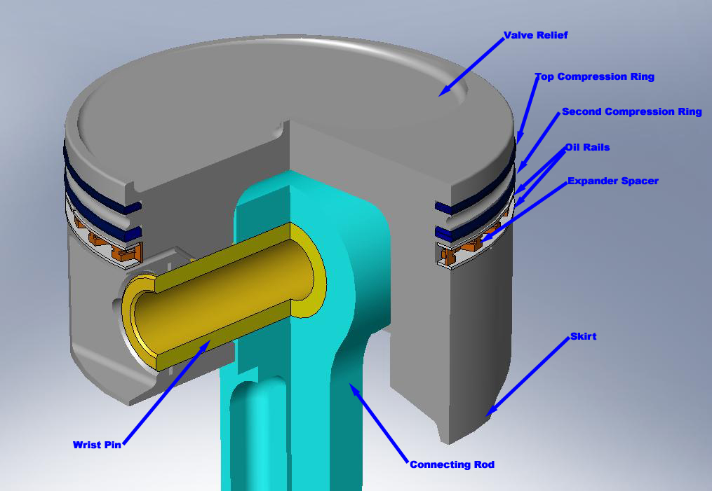
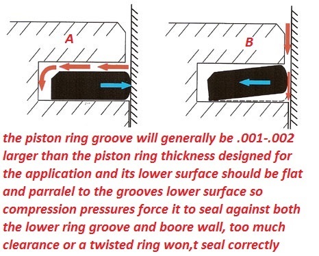
the piston rings must have vertical and back clearance in the piston ring grooves
common sbc pin height info
Specs
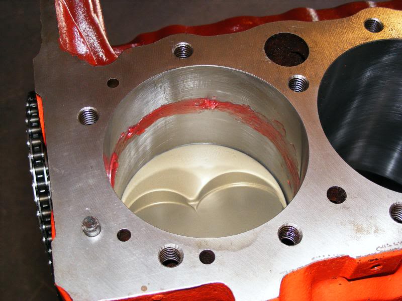
and calculate the required clearances after measuring your heads combustion chamber, and then do the correct machine work on your piston domes,
machining the domes for adequate,spark plug,clearance,
this is a very common issue and easily resolved,
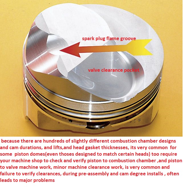
and it seldom costs much to have done.
common sbc pin height info
Specs
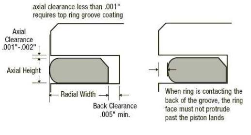
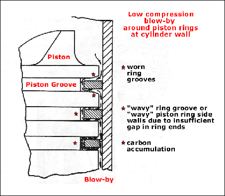

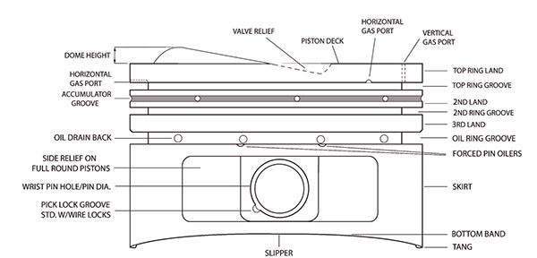
Piston Ring Groove Clearance
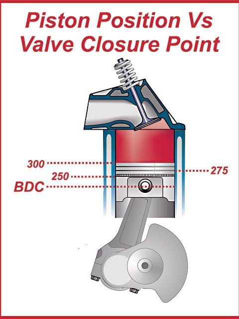
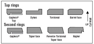
Pistons are grooved to fit rings that seal the cylinder’s compression and allow for lubrication of the cylinder walls. Piston rings come in a set. There are two compression rings. The top ring is affected by the most cylinder compression pressures. The second compression ring reinforces the top ring. The third ring down is the oil ring. It controls lubrication between the piston and cylinder bore.
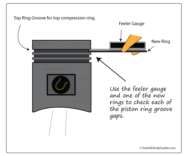
Place the new ring into the top piston groove, and then place a feeler gauge into the gap between the new ring and the upper land. Move around the pistons groove and obtain a few measurements. Compare this reading to specifications. If this reading is too much and the gap is too large, the piston must be replaced. The top ring takes the most compression. This causes the ring to slap against and wear the lands in the piston groove.
and of course the pistons must have the correct piston too bore clearance.
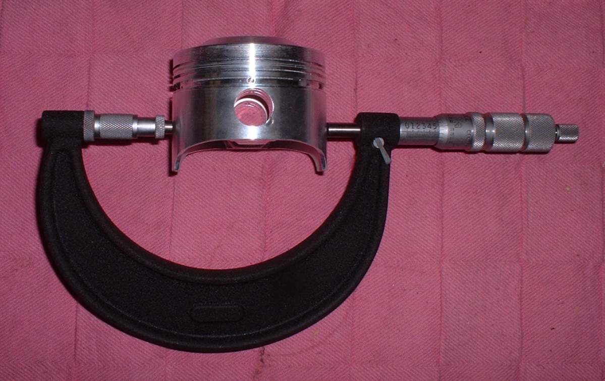
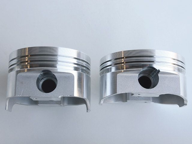
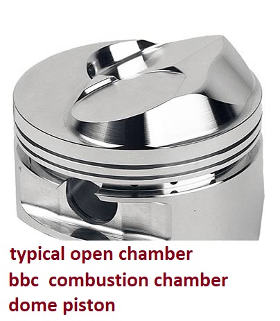
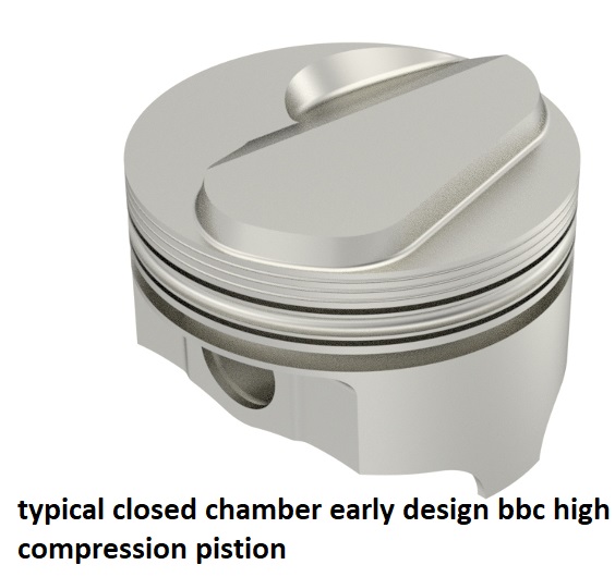
notice the pin height in the pistons pictured above allow a longer or shorter connecting rod length
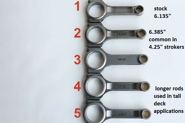
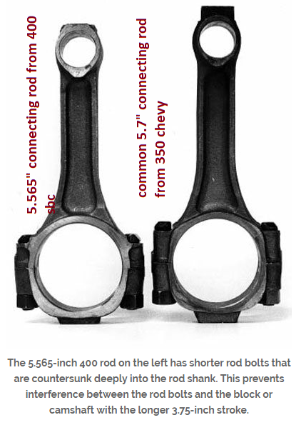
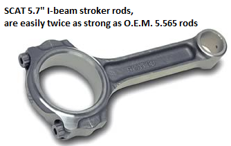
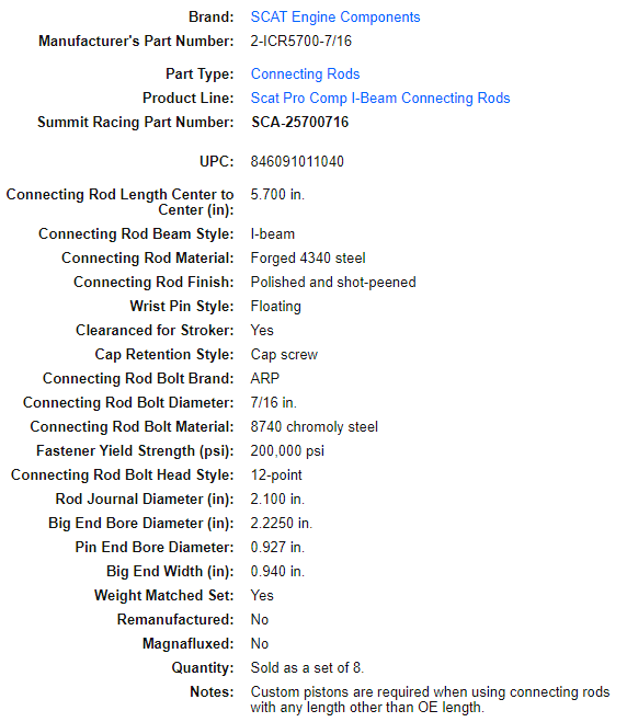
heres a selection of commonly available big block chevy connecting rod lengths
lets look at a quick example, say you want pistons for your 400sbc, you can select either 5.7" or 6" connecting rods for use in a 400 sbc, either is an improvement over the stock 5.565" connecting rods, most guys feel the 5.7" is the best choice due to the need to place the wrist pin up into the oil ring groove on pistons with the higher 6" rods required pin location and shorter piston compression height.
http://scatcrankshafts.com/#6
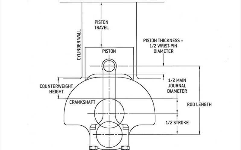
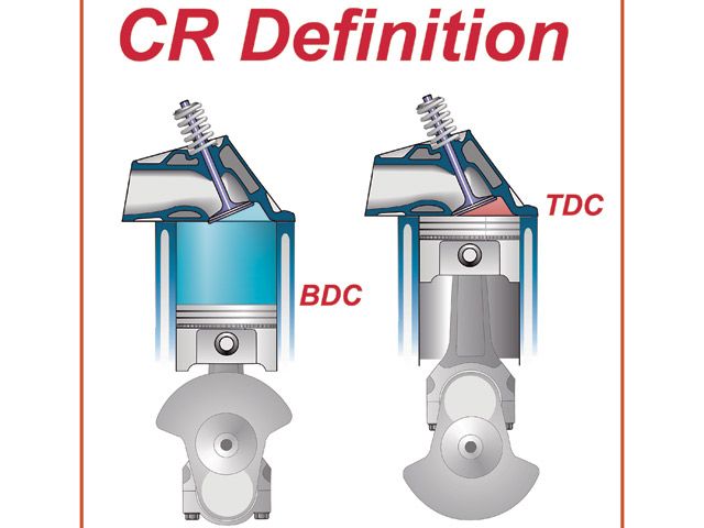
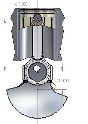
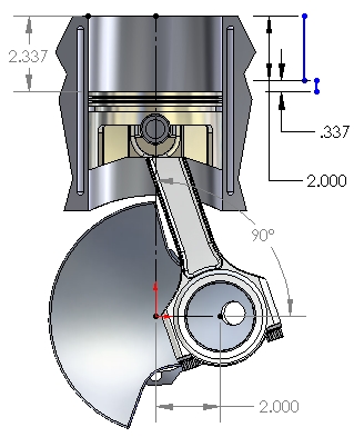
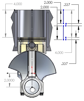
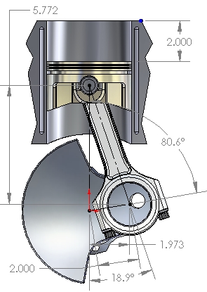
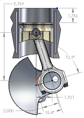
notice how the longer crank stroke effects the piston stroke distance in the bore, both at the lower and upper end of the cylinder
5.7" rod piston
https://www.uempistons.com/index.php?ma ... cts_id=149
6" rod piston
https://www.uempistons.com/index.php?ma ... cts_id=416
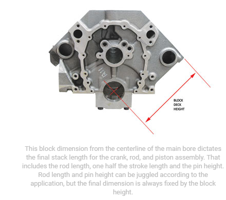
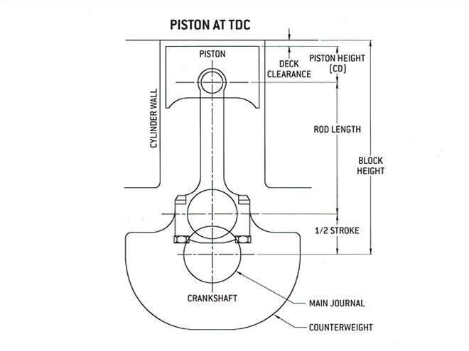
a small block has a 9" deck height, subtract 1/2 the stroke plus the rod length from that 9" to get the required pin height
most blocks actually measure between 9.00-9.023"
If you use a 5.7" rod in a 400 with its 3.75" stroke ,you need a 1.433 compression height .......because 1/2 of 3.75" stroke = 1.875" + 5.7"+1.433=9.008"
http://victorylibrary.com/mopar/rod-tech-c.htm
If you use a 6" rod in a 400 with its 3.75" stroke you need a 1.13 compression height.......because 1/2 of 3.75" stroke = 1.875" + 6"+1.13 =9.005"
http://www.lunatipower.com/Tech/Pistons ... eight.aspx
well the first thing youll need to do is get a machine shop to check the block for cracks, verify line bore straitness, look for the deck to be strait, and check for other problems, and sonic check the bore walls to see if it can be bored to .060 over bore to fit the pistons you have, have the pistons inspected and measured, before considering their re-use. now if that was a standard bore block with a standard deck the pistons would not work,but with the taller deck height of the tall deck block youve got a shot at using those components.
the standard compression height on a 454 piston is about 1.645" compression height,the stock rod is 6.135" and with a 4" stroke crank that adds up to a 9.78 total for the standard 9.8" deck block, but theres commonly about .023 extra deck thickness if its never been milled/decked
on your taller tall deck block with its 10.2"(plus .023") deck height you have a 454 piston is about 1.645" compression height, the stroke on a 496 is increased to 4.25" so you have 2.125"= 1.645" pin height and a 10.2" deck that leaves you with a 6.430-.6.453" potential rod length, the closest standard rod is a 6.385", leaving the piston deck at .010-.033 below the deck of the block before theres a head gasket added, the next longer rod is 6.535" you can find combos that can come close to fitting
be aware that the other common BBC piston pin heights are 1.270, 1.520 and 1.765",
bbc connecting rods come in 6.135", 6.385" ,6.535", 6.700" and 6.800"
obviously theres other combos if your willing to change connecting rods or pistons

http://www.wallaceracing.com/Calc-Deck- ... length.php

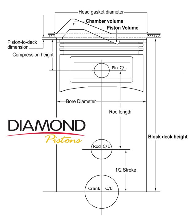
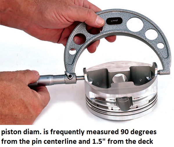
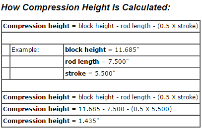
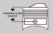
I,m amazed at how often this concept gets confused, basically a piston compression height or the distance from the center of the piston pin hole, to the pistons deck height , is supposed to be very close to the block deck height MINUS the connecting rod length and 1/2 the crank stroke.
theres three variables here, stroke rod length and piston pin height, the piston pin height must be low enough to allow the ring pack , but theres some latitude in measurements, a longer stroke will require either a shorter connecting rod or a shorter compression pin height , but you can for example use a longer rod and shorter piston pin height with the original stroke to gain some rod/stroke ratio or clear larger crank counter weights.
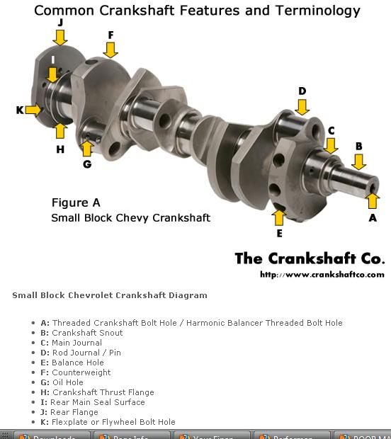
Chevy V8 bore & stroke chart
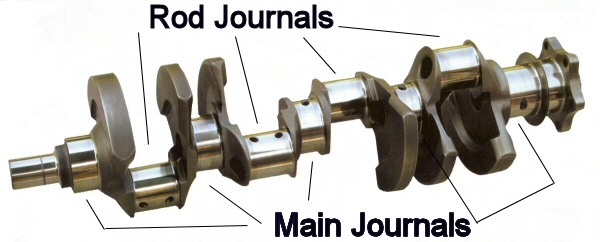
Chevy V8 Crankshaft Journal Sizes
Here's a list of Chevy V-8 crankshaft journal sizes. All journal sizes are given in "STANDARD" sizes. Your crankshaft may have been cut down in size previously by a machine shop. Make sure your crank will work in the block you have. Blocks were made for each crank main journal size. If you are putting a "small" or "medium" journal smallblock crank into a "medium" or "large" journal smallblock block you will need crank bearing "spacers" or use special "thick" bearings available from aftermarket suppliers.
Chevy Smallblock V8 Crankshaft Journal Sizes
Gen.I, "Small Journal"
265...Mains-2.30"-Rods-2.00"
283...Mains-2.30"-Rods-2.00"
302...Mains-2.30"-Rods-2.00"
327...Mains-2.30"-Rods-2.00"
Gen.I, "Medium Journal", includes "Vortec" 305 and 350 thru '98
262...Mains-2.45"-Rods-2.10"
267...Mains-2.45"-Rods-2.10"
302...Mains-2.45"-Rods-2.10"
305...Mains-2.45"-Rods-2.10"
307...Mains-2.45"-Rods-2.10"
327...Mains-2.45"-Rods-2.10"
350...Mains-2.45"-Rods-2.10"
Gen.I, "Large Journal"
400...Mains-2.65"-rods-2.10"
Non-production Gen.I combination, using Gen.I 400 crank in Gen.I 350 block
383...400 crank, Mains cut to 2.45"-Rods-2.10"
Non-production Gen.I combination, using Gen.I 350 crank in Gen.I 400 block
377..."Spacer" or "thick" main bearings with 350 crank-Rods-2.10"
Gen.II, "Medium Journal", includes "L-99" 265, "LT-1" 350, "LT-4" 350
265...Mains-2.45"-rods-2.10"
305...Mains-2.45"-Rods-2.10"
350...Mains-2.45"-Rods-2.10"
Non-production Gen.II combination, using Gen.II 265 "L-99" crank in Gen.II 350 block
302...Mains-2.45"-Rods-2.10"
Gen.III, includes '97-2005 "LS-1" Corvette, Firebird, Camaro
345...Mains-2.558"-Rods-2.10"
Corvette "ZR-1", DOHC, "LT-5"
350...Mains-2.76"-Rods-2.10"
CID BORE STROKE
262 = 3.671" x 3.10" (Gen. I, 5.7" rod)
265 = 3.750" x 3.00" ('55-'57 Gen.I, 5.7" rod)
265 = 3.750" x 3.00" ('94-'96 Gen.II, 4.3 liter V-8 "L99", 5.94" rod)
267 = 3.500" x 3.48" (Gen.I, 5.7" rod)
283 = 3.875" x 3.00" (Gen.I, 5.7" rod)
293 = 3.779" x 3.27" ('99-later, Gen.III, "LR4" 4.8 Liter Vortec, 6.278" rod)
302 = 4.000" x 3.00" (Gen.I, 5.7" rod)
305 = 3.736" x 3.48" (Gen.I, 5.7" rod)
307 = 3.875" x 3.25" (Gen.I, 5.7" rod)
325 = 3.779" x 3.622" ('99-later, Gen.III, "LM7", "LS4 front wheel drive V-8" 5.3 Liter Vortec, 6.098" rod)
327 = 4.000" x 3.25" (Gen.I, 5.7" rod)
345 = 3.893" x 3.622" ('97-later, Gen.III, "LS1", 6.098" rod)
350 = 4.000" x 3.48" (Gen.I, 5.7" rod)
350 = 4.000" x 3.48" ('96-'01, Gen. I, Vortec, 5.7" rod)
350 = 3.900" x 3.66" ('89-'95, "LT5", in "ZR1" Corvette 32-valve DOHC, 5.74" rod)
364 = 4.000" x 3.622" ('99-later, Gen.III, "LS2", "LQ4" 6.0 Liter Vortec, 6.098" rod)
376 = 4.065" x 3.622" (2007-later, Gen. IV, "L92", Cadillac Escalade, GMC Yukon)
383 = 4.000" x 3.80" ('00, "HT 383", Gen.I truck crate motor, 5.7" rod)
400 = 4.125" x 3.75" (Gen.I, 5.565" rod)
427 = 4.125" x 4.00" (2006 Gen.IV, LS7 SBC, titanium rods)
Two common, non-factory smallblock combinations:
377 = 4.155" x 3.48" (5.7" or 6.00" rod)
400 block and a 350 crank with "spacer" main bearings
383 = 4.030" x 3.75" (5.565" or 5.7" or 6.0" rod)
350 block and a 400 crank, main bearing crank journals
cut to 350 size
ALL production big blocks used a 6.135" length rod.
CHEVY BIG BLOCK V-8 BORE AND STROKE
366T = 3.935" x 3.76"
396 = 4.096" x 3.76"
402 = 4.125" x 3.76"
427 = 4.250" x 3.76"
427T = 4.250" x 3.76"
454 = 4.250" x 4.00"
477= 4.5" bore x 3.76" stroke
496 = 4.250" x 4.37" (2001 Vortec 8100, 8.1 liter)
502 = 4.466" x 4.00"
557T= 4.5 bore 4.375" stroke
572T = 4.560" x 4.375" (2003 "ZZ572" crate motors)
T = Tall Deck
ALL production big blocks used a 6.135" length rod.
read thru these links
viewtopic.php?f=53&t=3760&p=9968&hilit=clearances+skirt#p9968
viewtopic.php?f=50&t=1249
http://garage.grumpysperformance.com/index.php?threads/maximizing-piston-to-bore-ring-seal.3897/
http://garage.grumpysperformance.com/index.php?threads/piston-suppliers.2208/#post-5942
http://victorylibrary.com/mopar/rod-tech-c.htm
http://www.lunatipower.com/Tech/Pistons ... eight.aspx
http://www.kb-silvolite.com/calc.php?action=piston_comp
http://www.enginelabs.com/engine-tech/stroker-engines-the-long-and-short-of-connecting-rod-length/
http://www.jepistons.com/PDFs/TechCorner/2006-je10.pdf
http://www.csgnetwork.com/compcalc.html
http://www.gtsparkplugs.com/CompRatioCalc.html
http://www.summitracing.com/expertadviceandnews/calcsandtools/compression-calculator
https://www.rbracing-rsr.com/compstaticcalc.html
http://www.diamondracing.net/tools/
HEY GRUMPYVETTE?
I picked up a tall deck,Chevy big block 427, block, at a yard sale and a friend donated a set of 454 .060 pistons
Ive got several intakes for big block engines ,both oval and rectangular port, styles, whats it going to take to build a 496 stroker from these components?"
it should be rather obvious that youll need to know the exact distance the piston deck sits at TDC ,above or below the block deck surface and the valve notch recess or pop-up dome volume of the piston to do accurate quench or compression calculations
if you find the rotating assembly is more difficult to rotate than you expected, you may want to verify some clearance issues that get over looked at times,
theres also some, other potential issues,
theres a slight potential for the piston wrist pins too not rotate effortlessly in the piston pin bores ,
that may add to the difficulty in rotating the assembly in the block.
the piston rings must have vertical and back clearance in the piston ring grooves
common sbc pin height info
Specs
- Comp Height 5.565" Rod - 1.561
- Comp Height 5.7" Rod - 1.433
- Comp Height 6.0" Rod - 1.13
- Pin Diameter - 0.9272
and calculate the required clearances after measuring your heads combustion chamber, and then do the correct machine work on your piston domes,
machining the domes for adequate,spark plug,clearance,
this is a very common issue and easily resolved,
and it seldom costs much to have done.
common sbc pin height info
Specs
- Comp Height 5.565" Rod - 1.561
- Comp Height 5.7" Rod - 1.433
- Comp Height 6.0" Rod - 1.13
- Pin Diameter - 0.9272
Piston Ring Groove Clearance
Pistons are grooved to fit rings that seal the cylinder’s compression and allow for lubrication of the cylinder walls. Piston rings come in a set. There are two compression rings. The top ring is affected by the most cylinder compression pressures. The second compression ring reinforces the top ring. The third ring down is the oil ring. It controls lubrication between the piston and cylinder bore.
Place the new ring into the top piston groove, and then place a feeler gauge into the gap between the new ring and the upper land. Move around the pistons groove and obtain a few measurements. Compare this reading to specifications. If this reading is too much and the gap is too large, the piston must be replaced. The top ring takes the most compression. This causes the ring to slap against and wear the lands in the piston groove.
and of course the pistons must have the correct piston too bore clearance.
notice the pin height in the pistons pictured above allow a longer or shorter connecting rod length
heres a selection of commonly available big block chevy connecting rod lengths
lets look at a quick example, say you want pistons for your 400sbc, you can select either 5.7" or 6" connecting rods for use in a 400 sbc, either is an improvement over the stock 5.565" connecting rods, most guys feel the 5.7" is the best choice due to the need to place the wrist pin up into the oil ring groove on pistons with the higher 6" rods required pin location and shorter piston compression height.
http://scatcrankshafts.com/#6
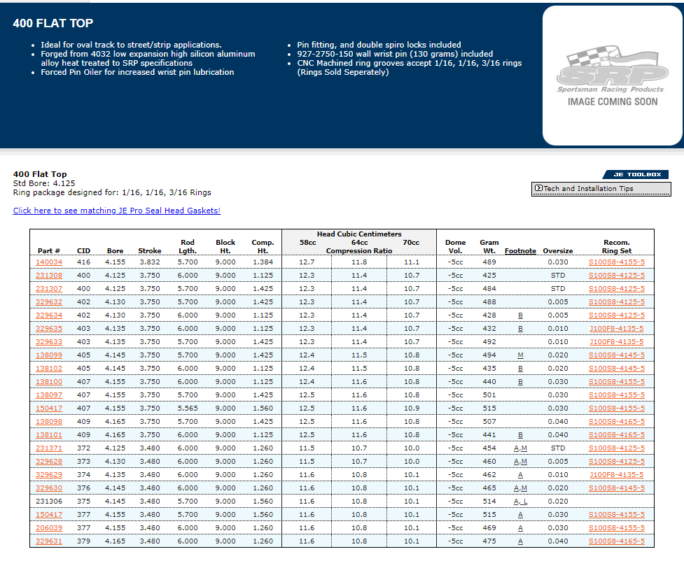
notice how the longer crank stroke effects the piston stroke distance in the bore, both at the lower and upper end of the cylinder
5.7" rod piston
https://www.uempistons.com/index.php?ma ... cts_id=149
6" rod piston
https://www.uempistons.com/index.php?ma ... cts_id=416
a small block has a 9" deck height, subtract 1/2 the stroke plus the rod length from that 9" to get the required pin height
most blocks actually measure between 9.00-9.023"
If you use a 5.7" rod in a 400 with its 3.75" stroke ,you need a 1.433 compression height .......because 1/2 of 3.75" stroke = 1.875" + 5.7"+1.433=9.008"
http://victorylibrary.com/mopar/rod-tech-c.htm
If you use a 6" rod in a 400 with its 3.75" stroke you need a 1.13 compression height.......because 1/2 of 3.75" stroke = 1.875" + 6"+1.13 =9.005"
http://www.lunatipower.com/Tech/Pistons ... eight.aspx
well the first thing youll need to do is get a machine shop to check the block for cracks, verify line bore straitness, look for the deck to be strait, and check for other problems, and sonic check the bore walls to see if it can be bored to .060 over bore to fit the pistons you have, have the pistons inspected and measured, before considering their re-use. now if that was a standard bore block with a standard deck the pistons would not work,but with the taller deck height of the tall deck block youve got a shot at using those components.
the standard compression height on a 454 piston is about 1.645" compression height,the stock rod is 6.135" and with a 4" stroke crank that adds up to a 9.78 total for the standard 9.8" deck block, but theres commonly about .023 extra deck thickness if its never been milled/decked
on your taller tall deck block with its 10.2"(plus .023") deck height you have a 454 piston is about 1.645" compression height, the stroke on a 496 is increased to 4.25" so you have 2.125"= 1.645" pin height and a 10.2" deck that leaves you with a 6.430-.6.453" potential rod length, the closest standard rod is a 6.385", leaving the piston deck at .010-.033 below the deck of the block before theres a head gasket added, the next longer rod is 6.535" you can find combos that can come close to fitting
be aware that the other common BBC piston pin heights are 1.270, 1.520 and 1.765",
bbc connecting rods come in 6.135", 6.385" ,6.535", 6.700" and 6.800"
obviously theres other combos if your willing to change connecting rods or pistons
http://www.wallaceracing.com/Calc-Deck- ... length.php
I,m amazed at how often this concept gets confused, basically a piston compression height or the distance from the center of the piston pin hole, to the pistons deck height , is supposed to be very close to the block deck height MINUS the connecting rod length and 1/2 the crank stroke.
theres three variables here, stroke rod length and piston pin height, the piston pin height must be low enough to allow the ring pack , but theres some latitude in measurements, a longer stroke will require either a shorter connecting rod or a shorter compression pin height , but you can for example use a longer rod and shorter piston pin height with the original stroke to gain some rod/stroke ratio or clear larger crank counter weights.
Chevy V8 bore & stroke chart
Chevy V8 Crankshaft Journal Sizes
Here's a list of Chevy V-8 crankshaft journal sizes. All journal sizes are given in "STANDARD" sizes. Your crankshaft may have been cut down in size previously by a machine shop. Make sure your crank will work in the block you have. Blocks were made for each crank main journal size. If you are putting a "small" or "medium" journal smallblock crank into a "medium" or "large" journal smallblock block you will need crank bearing "spacers" or use special "thick" bearings available from aftermarket suppliers.
Chevy Smallblock V8 Crankshaft Journal Sizes
Gen.I, "Small Journal"
265...Mains-2.30"-Rods-2.00"
283...Mains-2.30"-Rods-2.00"
302...Mains-2.30"-Rods-2.00"
327...Mains-2.30"-Rods-2.00"
Gen.I, "Medium Journal", includes "Vortec" 305 and 350 thru '98
262...Mains-2.45"-Rods-2.10"
267...Mains-2.45"-Rods-2.10"
302...Mains-2.45"-Rods-2.10"
305...Mains-2.45"-Rods-2.10"
307...Mains-2.45"-Rods-2.10"
327...Mains-2.45"-Rods-2.10"
350...Mains-2.45"-Rods-2.10"
Gen.I, "Large Journal"
400...Mains-2.65"-rods-2.10"
Non-production Gen.I combination, using Gen.I 400 crank in Gen.I 350 block
383...400 crank, Mains cut to 2.45"-Rods-2.10"
Non-production Gen.I combination, using Gen.I 350 crank in Gen.I 400 block
377..."Spacer" or "thick" main bearings with 350 crank-Rods-2.10"
Gen.II, "Medium Journal", includes "L-99" 265, "LT-1" 350, "LT-4" 350
265...Mains-2.45"-rods-2.10"
305...Mains-2.45"-Rods-2.10"
350...Mains-2.45"-Rods-2.10"
Non-production Gen.II combination, using Gen.II 265 "L-99" crank in Gen.II 350 block
302...Mains-2.45"-Rods-2.10"
Gen.III, includes '97-2005 "LS-1" Corvette, Firebird, Camaro
345...Mains-2.558"-Rods-2.10"
Corvette "ZR-1", DOHC, "LT-5"
350...Mains-2.76"-Rods-2.10"
CID BORE STROKE
262 = 3.671" x 3.10" (Gen. I, 5.7" rod)
265 = 3.750" x 3.00" ('55-'57 Gen.I, 5.7" rod)
265 = 3.750" x 3.00" ('94-'96 Gen.II, 4.3 liter V-8 "L99", 5.94" rod)
267 = 3.500" x 3.48" (Gen.I, 5.7" rod)
283 = 3.875" x 3.00" (Gen.I, 5.7" rod)
293 = 3.779" x 3.27" ('99-later, Gen.III, "LR4" 4.8 Liter Vortec, 6.278" rod)
302 = 4.000" x 3.00" (Gen.I, 5.7" rod)
305 = 3.736" x 3.48" (Gen.I, 5.7" rod)
307 = 3.875" x 3.25" (Gen.I, 5.7" rod)
325 = 3.779" x 3.622" ('99-later, Gen.III, "LM7", "LS4 front wheel drive V-8" 5.3 Liter Vortec, 6.098" rod)
327 = 4.000" x 3.25" (Gen.I, 5.7" rod)
345 = 3.893" x 3.622" ('97-later, Gen.III, "LS1", 6.098" rod)
350 = 4.000" x 3.48" (Gen.I, 5.7" rod)
350 = 4.000" x 3.48" ('96-'01, Gen. I, Vortec, 5.7" rod)
350 = 3.900" x 3.66" ('89-'95, "LT5", in "ZR1" Corvette 32-valve DOHC, 5.74" rod)
364 = 4.000" x 3.622" ('99-later, Gen.III, "LS2", "LQ4" 6.0 Liter Vortec, 6.098" rod)
376 = 4.065" x 3.622" (2007-later, Gen. IV, "L92", Cadillac Escalade, GMC Yukon)
383 = 4.000" x 3.80" ('00, "HT 383", Gen.I truck crate motor, 5.7" rod)
400 = 4.125" x 3.75" (Gen.I, 5.565" rod)
427 = 4.125" x 4.00" (2006 Gen.IV, LS7 SBC, titanium rods)
Two common, non-factory smallblock combinations:
377 = 4.155" x 3.48" (5.7" or 6.00" rod)
400 block and a 350 crank with "spacer" main bearings
383 = 4.030" x 3.75" (5.565" or 5.7" or 6.0" rod)
350 block and a 400 crank, main bearing crank journals
cut to 350 size
ALL production big blocks used a 6.135" length rod.
CHEVY BIG BLOCK V-8 BORE AND STROKE
366T = 3.935" x 3.76"
396 = 4.096" x 3.76"
402 = 4.125" x 3.76"
427 = 4.250" x 3.76"
427T = 4.250" x 3.76"
454 = 4.250" x 4.00"
477= 4.5" bore x 3.76" stroke
496 = 4.250" x 4.37" (2001 Vortec 8100, 8.1 liter)
502 = 4.466" x 4.00"
557T= 4.5 bore 4.375" stroke
572T = 4.560" x 4.375" (2003 "ZZ572" crate motors)
T = Tall Deck
ALL production big blocks used a 6.135" length rod.
read thru these links
viewtopic.php?f=53&t=3760&p=9968&hilit=clearances+skirt#p9968
viewtopic.php?f=50&t=1249
http://garage.grumpysperformance.com/index.php?threads/maximizing-piston-to-bore-ring-seal.3897/
http://garage.grumpysperformance.com/index.php?threads/piston-suppliers.2208/#post-5942
http://victorylibrary.com/mopar/rod-tech-c.htm
http://www.lunatipower.com/Tech/Pistons ... eight.aspx
http://www.kb-silvolite.com/calc.php?action=piston_comp
http://www.enginelabs.com/engine-tech/stroker-engines-the-long-and-short-of-connecting-rod-length/
http://www.jepistons.com/PDFs/TechCorner/2006-je10.pdf
http://www.csgnetwork.com/compcalc.html
http://www.gtsparkplugs.com/CompRatioCalc.html
http://www.summitracing.com/expertadviceandnews/calcsandtools/compression-calculator
https://www.rbracing-rsr.com/compstaticcalc.html
http://www.diamondracing.net/tools/
Last edited by a moderator: