Submitted By Cuda66273
This article written by Harvey Crane and sent to me by Harvey himself.
I had a nice long fireside type chat with Harvey last week, he and I bantered the pro's and con's of square Vs. split cams, we chuckled about the 1.6 rockers on the exhaust side, we rolled over laughing about the big split duration cams with a 114 centerline and how the marketing depts. have taken over the cam designs just to print big numbers to try and sell more cams.....it was a very interesting conversation with one of the best cam designers in the world. The end of the conversation was basically he warned me that cam design is only as good as the Guy's opinion that your talking to and to what end goal they are trying to achieve...is it power or big numbers?....
Here's the article:
"SECRETS OF A CAM DESIGNER"
BY HARVEY CRANE
"CAM PROFILE INTENSITY" and "SPAN" WHAT DO THEY MEAN ?
One of the secrets of raising horsepower without sacrificing low speed and mid-range torque is in selecting the right high performance camshaft. That means matching the cam to the speed range in which an engine operates. In spite of the fact that some people believe bigger is better, it is often true that less duration means more usable torque and horsepower.
Before cam duration can be matched to an engines operating range, the exact cam lift must be specified at where the duration is computed. If a statement is made "this cam has 260 degrees of duration", without adding "260 degrees at .050", the duration number of 260 degrees is TOTALLY USELESS.
That's why knowledgeable engine builders usually select a camshaft based on its duration at .05000" cam lift. In addition to being more accurate than "advertised duration" as an indication of a cam's performance potential, duration at .05000" lift applies almost universally, regardless of camshaft make, model or manufacturer.
"Advertised duration" varies depending upon who wrote the advertising. Most original equipment manufacturers (OEM'S) duration specifications for their hydraulic camshafts are specified at something less than the .00400" tappet lift suggested by SAE standard J-604 5.1. Other firms compute duration at .00600" or .00800" of cam lift.
With mechanical lifter racing profiles, advertised durations are usually computed at .01800", .02000" or .02200" of lift. As is the case with hydraulic profiles, advertised durations of mechanical and roller tappet cams can be compared only if the timing cam lift data point baselines are the same.
There are a number of reasons that a hydraulic lifter cam may have its duration computed at something other than .00400" cam lift. In some instances, a cam grinder who has used an exacting timing point for many years may be reluctant to change.
Another sound reason is that new technology can alter performance relative to duration at .00400" lift. Using a different timing point baseline in the computation of advertised duration may therefore be instrumental in reducing the tendency to over cam an engine. But most commonly, duration is rated at a nonstandard lift point as a means of enhancing specifications as compared to those of a competitive cam.
As an example, if one company has a popular racing hydraulic camshaft that has an advertised duration (computed at .00400" cam lift) of 302 degrees, a competitive cam grinder may think that his cam will sell better if it is advertised as having more than 302 degrees of duration. This caters to the "bigger is better" philosophy. Therefore, the competitive cam may be rated at .00200" lift, in which case its duration could be 308 degrees.
At the other end of the spectrum, with cams designed for use in mild street engines, or intended to enhance fuel economy, a manufacturer may rate its hydraulic cams at .006" tappet lift. When specifications are listed, this will make the cam appear "shorter" (have less duration) than those of the competition.
For mild street applications, less duration is frequently more desirable. So again, by playing the numbers game, a manufacturer can make its line of cams seem more attractive than those produced by other cam grinders.
Another point to consider is that with an underrated advertised duration, a cam will appear to be producing surprisingly more horsepower than an "equivalent" profile from a competing manufacturer. In fact, what you have is not a valid comparison because two cams with similar advertised durations will have considerably different ACTUAL valve timing, if their durations are not computed at the same amount of cam lift.
With all the variations in timing point baselines, making cam duration comparisons can be more confusing than trying to figure who's really doing what to whom in a television soap opera!
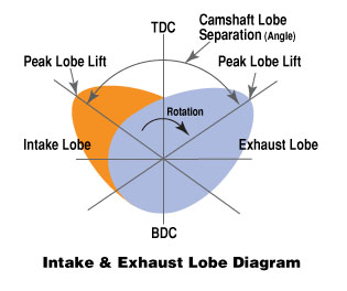
When comparing camshaft specifications, the best way to cut through the confusion is to focus on duration at .050" lift and lobe separation. These two figures will provide a solid indication of a cam's performance characteristics.
There are three other specifications that are very important. I call them "HYDRAULIC INTENSITY", "MINOR INTENSITY and "MAJOR INTENSITY". These terms were developed as a means of evaluating a camshaft's BROAD RANGE operational efficiency.
HYDRAULIC INTENSITY may be computed by subtracting duration at .05000" cam lift from duration at .00400" cam lift.
A cam with a duration of 280 degrees @.00400" cam lift and a duration of 220 degrees at .05000" cam lift has a HYDRAULIC INTENSITY of 60.00 degrees.
MINOR INTENSITY may be computed by subtracting duration at .05000" cam lift from duration at .01000" cam lift.
MAJOR INTENSITY may be computed by subtracting duration at .05000" cam lift from duration at .02000" cam lift.
In my personal opinion, the smaller the INTENSITY numbers measure, the performance will INCREASE!
The ideal cam profile would raise the valves to full lift instantly, hold them open for a specified duration and then close them instantly. The laws of physics make it impossible to achieve instantaneous valve opening and closing, but recent advancements in design technology have made it possible to open and close the valves with more area under the lift curve. By so doing, engine efficiency is improved because the valves spend less time at very low lift.
In practical terms, if two cams with similar lobe designs have the same duration at .05000" lift, maximum torque and horsepower will be almost identical. However, the cam with the smaller HYDRAULIC, MINOR or MAJOR INTENSITY figure will have a smoother idle, better off-idle response, superior low speed drivability and a broader power curve.
Viewed from another perspective, a lower HYDRAULIC, MINOR or MAJOR INTENSITY number translates to more low end power, without any loss of top end power. It also means that with a highly modified engine, it may be practical to install a cam with slightly longer duration at .05000" cam lift that might otherwise not be practical.
This lower INTENSITY solves many problems of poor idle quality which may effect Computer Controlled engines. Compatibility problems with torque converter stall speeds are also minimized.
State-of-the-art lobe designs therefore, deliver "MORE CAM" per dollar because they produce more power over a wider rpm band.
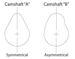
Now let me try to explain SPAN. I define SPAN with the following notation:
(00.00/00.00)
If a profile is SYMMETRICAL the numbers on each side of the / will be the same. Example, a mechanical tappet profile with a MAJOR INTENSITY of 34.00 degrees would have a MAJOR INTENSITY SPAN of (17.00/17.00).
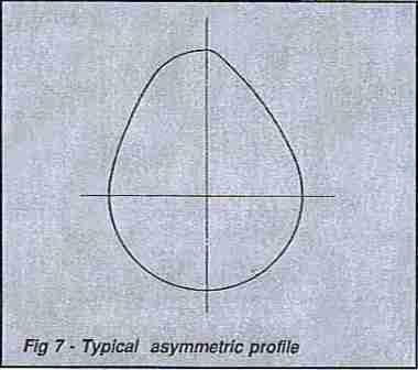
If this profile was NON-SYMMETRICAL with the same MAJOR INTENSITY of 34.00 degrees the MAJOR INTENSITY SPAN could be (16.00/18.00), (15.00/19.00) or possibly (14.50/19.50).
Almost all HYDRAULIC lifter profiles are NON-SYMMETRICAL and the numbers on each side of the / will be DIFFERENT. Example, a hydraulic lifter profile with a HYDRAULIC INTENSITY of 56.00 degrees could have a HYDRAULIC INTENSITY SPAN of (24.00/32.00). These are the PUBLISHED numbers from the HMV series of profiles (HMV means "Hydraulic Maximum Velocity" from the cam manufacturer on Fentress Boulevard in Daytona Beach, Florida.
Remember that the SPAN numbers inside of the two brackets MUST add up to the TOTAL INTENSITY.
"HAPPY CAM ANALYSIS TO YOU"
Harvey Crane