busterrm
solid fixture here in the forum
Degreeing – In the Camshaft
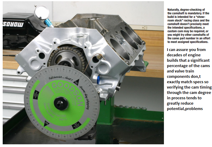
New racing camshafts have a cam card included that shows the specifications for that camshaft. Degreeing In the cam means verifying that the valve timing and lift are close the specifications printed on the cam card. There are several reasons to degree in a camshaft including:
• Checking for mislabeled camshafts - you may have purchased a camshaft that was mislabeled or placed in the wrong box.
• Verifying valve events - for most applications, it is reasonable to expect that the actual valve opening and closing events are within two degrees of the specifications printed on the cam card and within a few thousandths of the listed lobe lift.
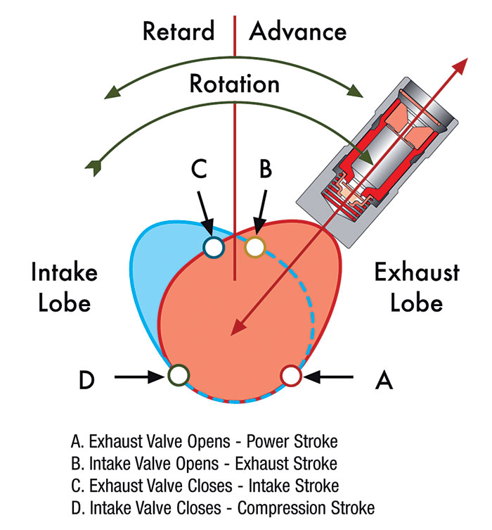
• Checking camshaft phasing - the actual lift and duration may be correct, but the camshaft phasing may be wrong if the sprocket locating dowel is positioned incorrectly. This doesn’t necessarily mean that you must return the camshaft – you may be able to correct the phasing problem. Also, racers and engine builders sometimes find that a particular camshaft works better if it is advanced or retarded a degree or two from the manufacturer’s recommended location.
These are the steps for degreeing-in a camshaft:
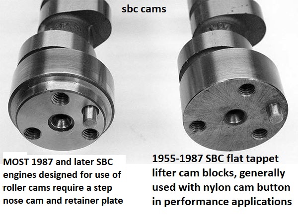
1. Install the camshaft.
2. Install the crank, piston & rod assembly, and cam drive assembly
3. Mount and adjust the degree wheel & pointer.
4. Install #1 lifters and dial indicator.
5. Determine the valve opening location, lobe lift, & valve closing location.
6. Calculate & correct the camshaft phasing.
Step #1 , Install the Camshaft:
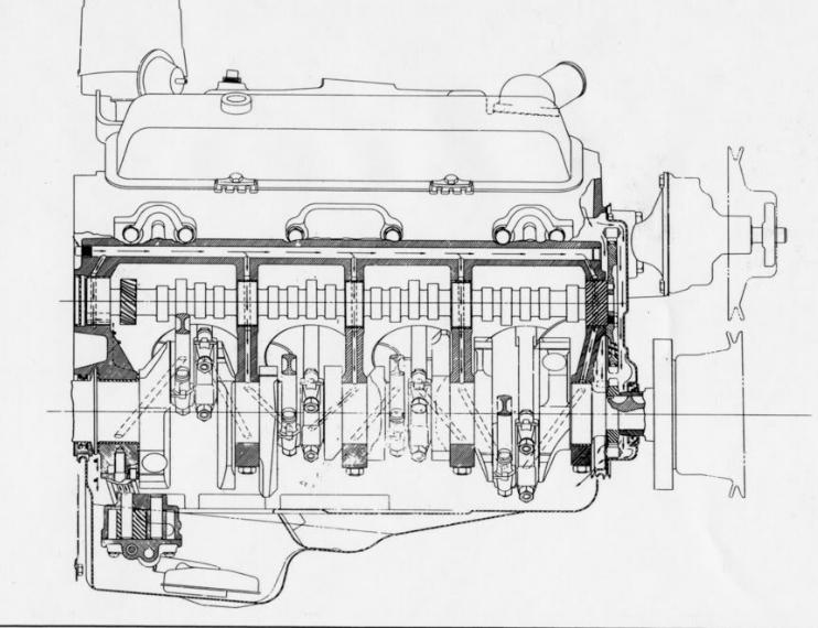
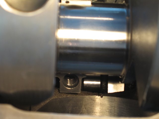
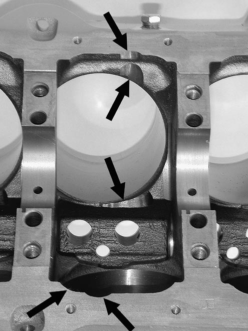
Apply oil to the cam journals and lobes. Rotate and slide the camshaft into the block. Support and rotate the camshaft as you install it.
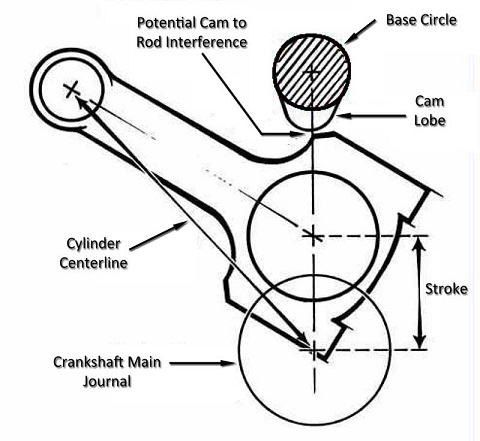
Step #2, Install the Crank, Piston & Rod Assembly, and Cam Drive Assembly:
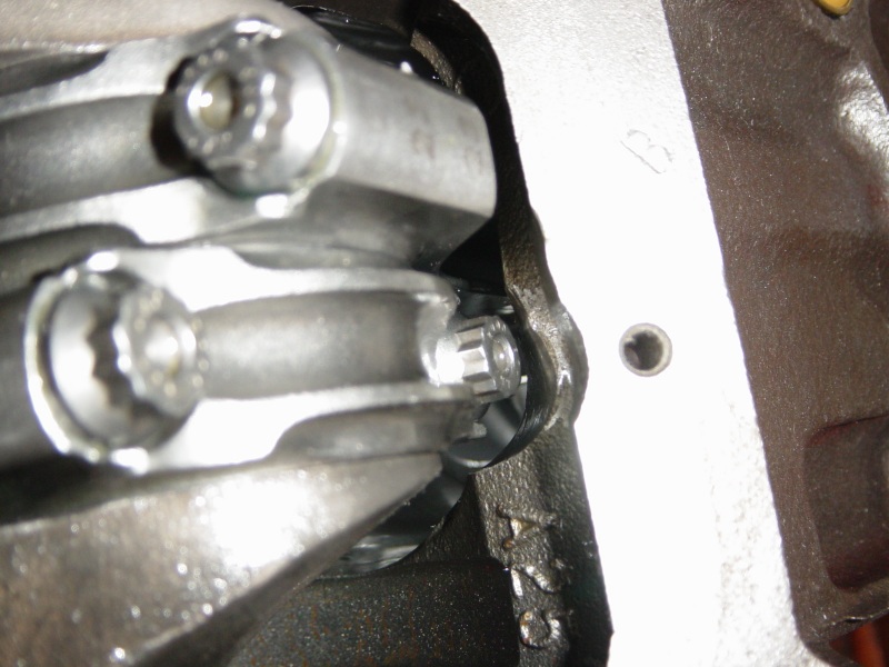
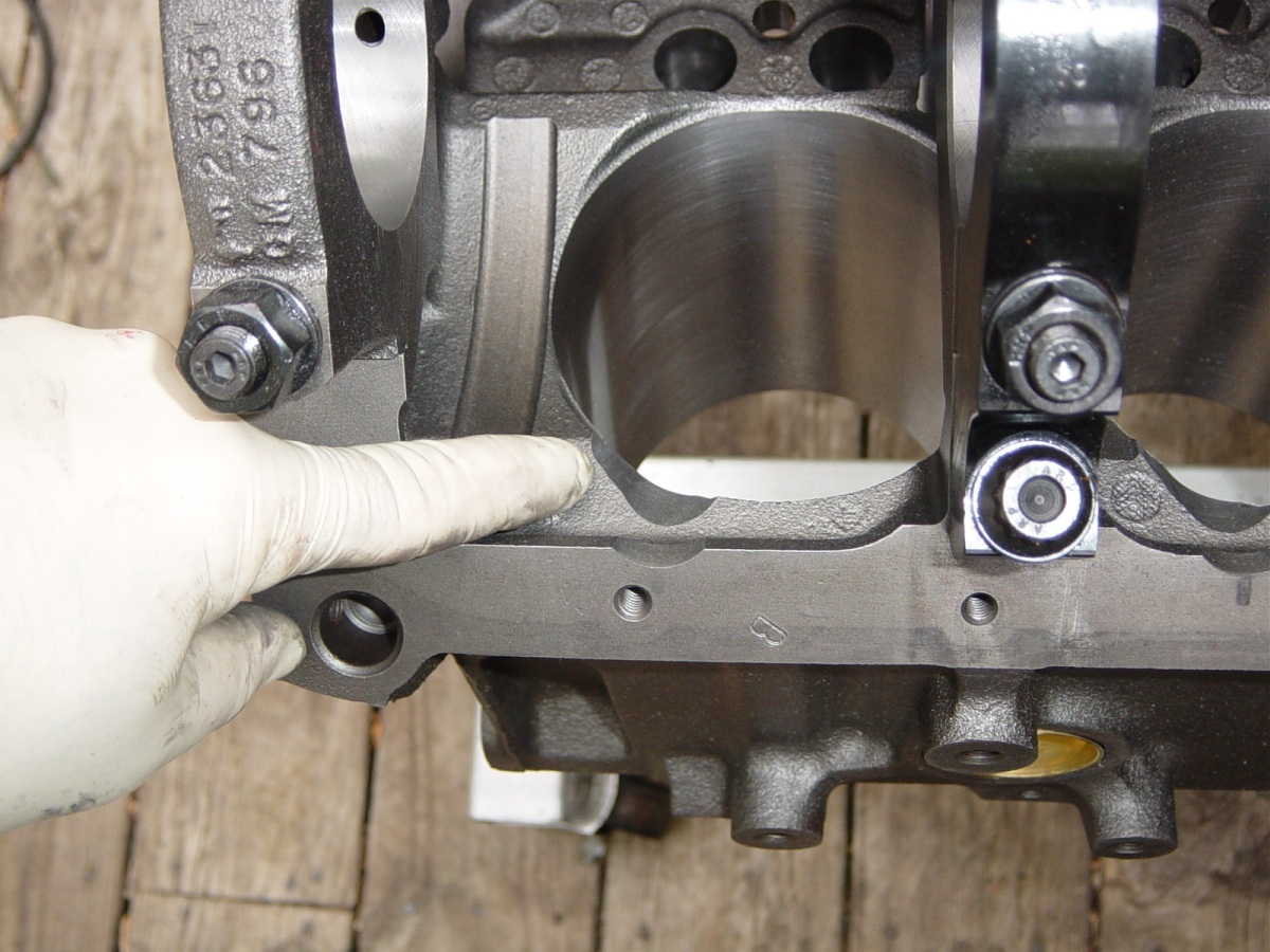
Clean the engine block and crankshaft. Lubricate the main bearings and install the crankshaft. Lubricate and install the main caps, then tighten the bolts or nuts enough to seat the caps. Apply some motor oil on the #1 cylinder wall, and then stabilize the the #1 piston in the bore by wrapping the ring grooves with an even layer of masking tape. Install the piston & rod assembly with rod bearings. Lubricate and snug the rod cap enough to seat it.
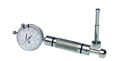
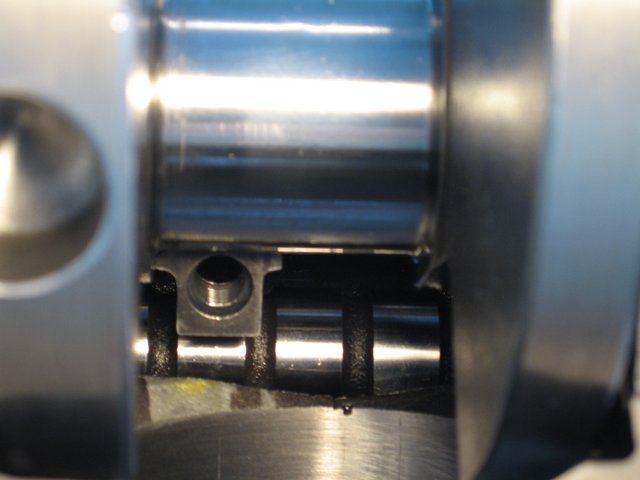
Install the front plate and cam thrust hardware with two nuts. Follow the instructions supplied with your cam drive kit. If a thrust plate is used, be sure to check the installed thrust clearance (end play). Set up a dial indicator and push the cam as far as it will go in one direction. Zero the dial, and push the cam the opposite way. The dial will read the cam thrust clearance. Make this measurement several times to be sure it is repeatable and accurate.
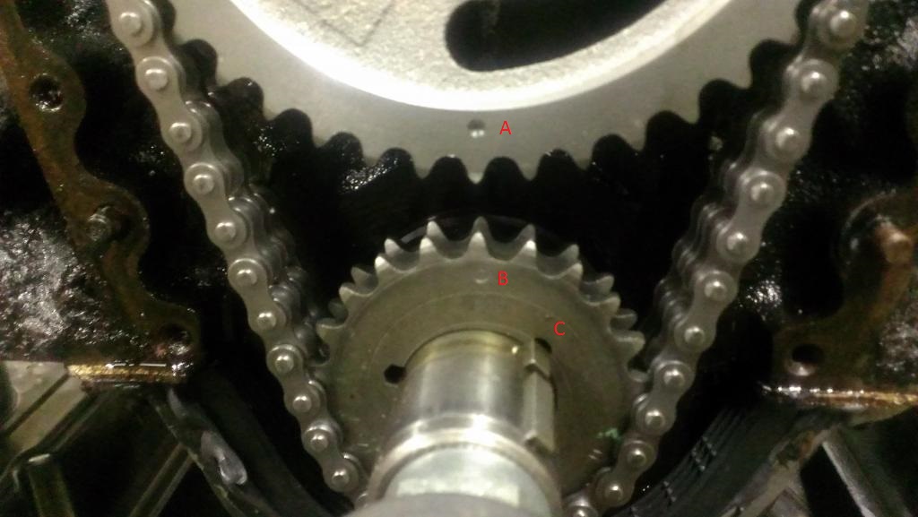
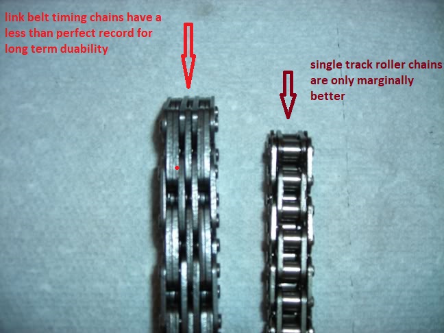
Install the crank sprocket or pulley, chain or belt, and cam sprocket or pulley as a unit. Install with pips on both gears or pulleys at the standard “0” alignment marks. Some drive assemblies have other markings for phasing the cam, use the standard setting.
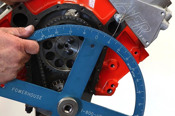
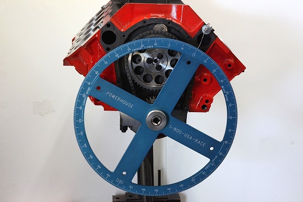
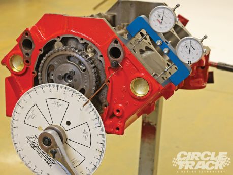
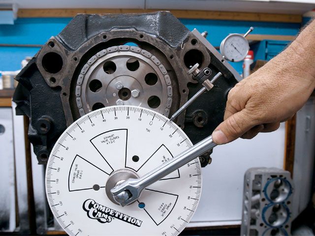
Step #3, Mount and Adjust the Degree Wheel & Pointer:
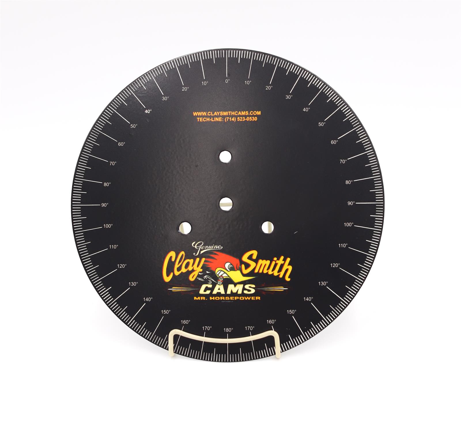
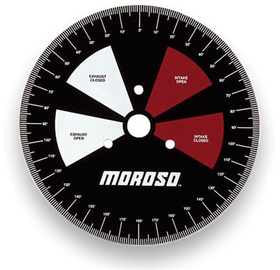
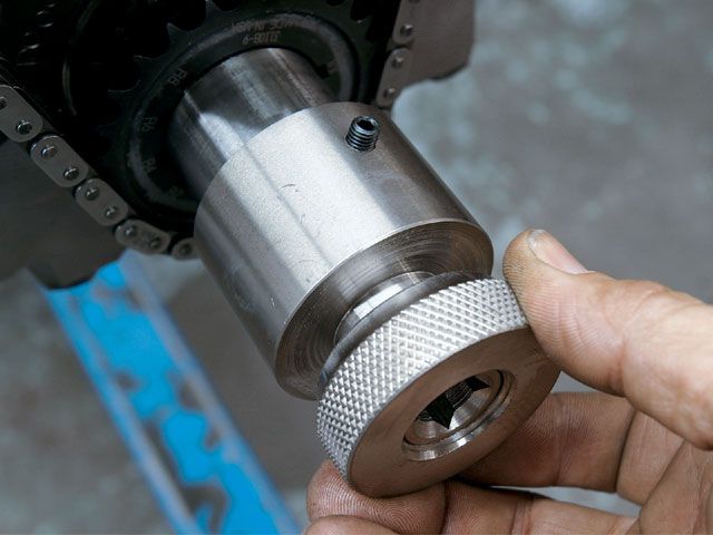
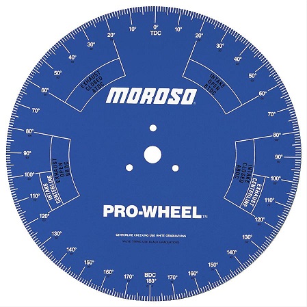
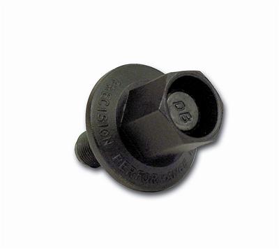
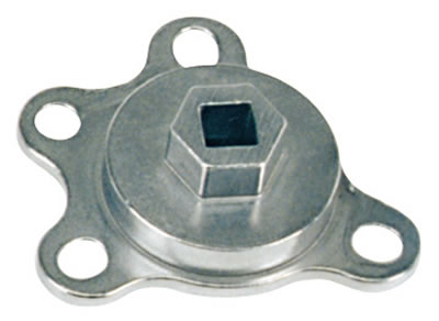
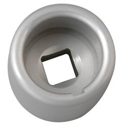
A degree wheel is a round plate that has degree marks to 180 degrees on either side of TDC and/or for all 360 degrees of crankshaft rotation. Most degree wheels mount to a crank turning socket. Install the socket first, and tighten the set screw. Be sure the woodruff key is in place and that you are using the correct socket. Install the degree wheel on the crank turning socket and tighten the knurled nut securely. Attach a pointer to a fixed location on the block.
To adjust the degree wheel, rotate the until the #1 piston is at TDC. Move the pointer or degree wheel so that the reading is at zero degrees.
NOTE: Piston movement slows down significantly near TDC. This effect is sometimes referred to as piston dwell. Near the top, a degree or two of crankshaft rotation makes very little measurable difference in piston location. This makes it more difficult to determine when the #1 piston is exactly at TDC.
To overcome errors related to piston dwell, find TDC by using a standard piston checking depth. Position the #1 piston so that it is down in the bore an exact distance both before and after TDC. Then rotate the crankshaft until it is exactly halfway between those locations.
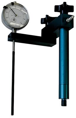
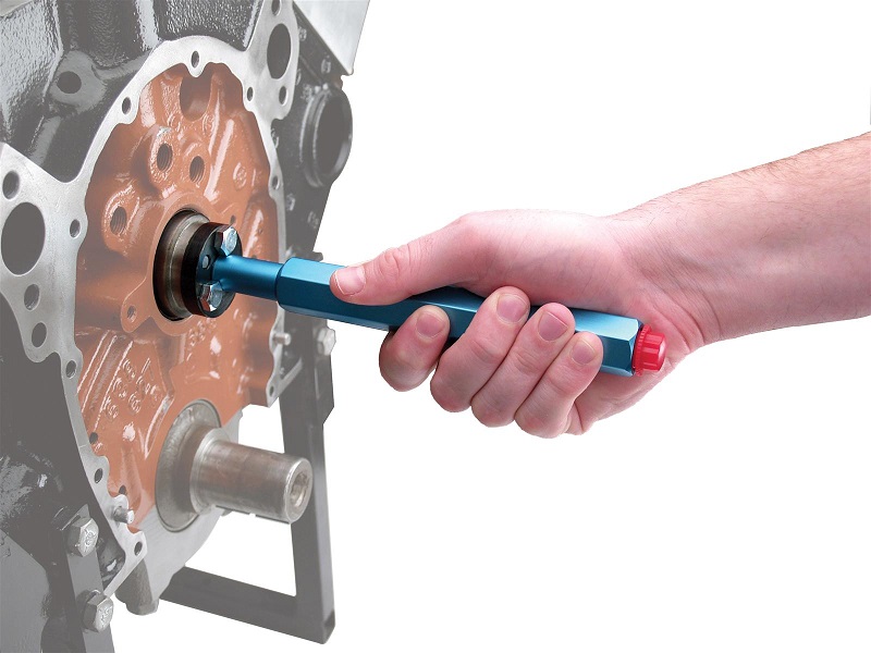
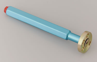
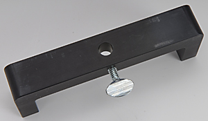
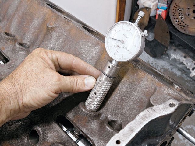
One way to create a checking depth is by using a piston stop. A piston stop is a metal bar that bolts across the block deck and mechanically stops piston travel. Some builders use them, but using a dial indicator with the piston stop to find the checking depth will provide you with a more accurate TDC adjustment. It also eliminates the chance of denting the soft aluminum piston.
First, you must make a rough TDC adjustment. Mount the dial indicator on the deck bridge (piston stop) and position it over the #1 piston. The piston rocks on its pin, so apply pressure in one direction so that you have repeatable readings. Use a long bar to engage the crank turning socket, and rotate the crankshaft until you find the high point in piston travel (TDC). Zero the dial indicator, then adjust the degree wheel or bend the pointer to required to indicate zero degrees (TDC).
Step #4, Install # 1 Lifters and Dial Indicator:
Lubricate the lifters, and slide them into the lifter bores for the # 1 cylinder. If the lifters are roller tappets, be sure to install the link bar that prevents lifter rotation.
Identify the # 1 intake lifter. If the pistons have valve reliefs, look for the lifter that corresponds to the larger (intake) valve relief on the piston. You can also determine the order of lifter bores by inspecting the valve layout on the cylinder head.
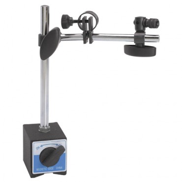
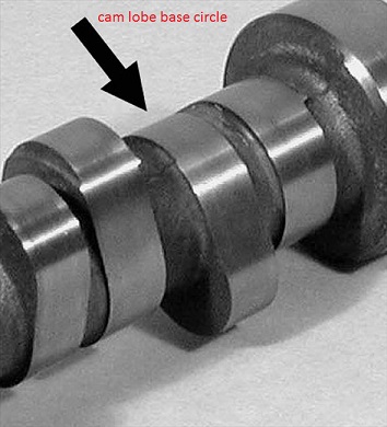
Mount the dial indicator so that it is in straight contact with the # 1 lifter. Rotate the crankshaft, and adjust the dial so it reads zero when the lifter is all the way down (on the base circle).
You are set up now and ready to degree in your cam.
Step # 5, Determine Valve Opening Location, Lift, & Closing Locations:
The specifications are on the cam card that is shipped with your camshaft, have it handy to compare with your findings.
NOTE: Due to the slack in timing chains or belts, you must always approach locations when degreeing – in the cam by turning the crankshaft clockwise, (the same direction it rotates when the engine is running). If you turn the crank too far, turn it back some distance, and get a “running start” at it again with a clockwise rotation. This ensures the accuracy of the your degree measurements. The checking height may vary, you may want seat to seat measurements in which case the checking height will be .006, or you can use a checking height of .050. For general purposes I am going to use .006(seat to seat). You can still degree at both checking heights to verify all the specs on your cam card.
Intake Open – Turn the crank clockwise until the dial indicator shows that the intake lifter has risen .006 checking height shown on the cam card. Record the degrees BTDC (before TDC) indicated on the wheel.
Intake Lobe Lift – Turn the crank slowly clockwise. The reading on the dial will increase steadily as the lifter rises. When the dial reading begins to decrease, rotate the crank back and forth until you find the highest reading. Be sure to count the full revolutions of the dial, each revolution is equal to .100, add the number of revolutions (times .100) to the reading on the dial at the highest point on the lobe. That is your total lobe lift, record that measurement. Actual lift at the valve you will multiple that number by your rocker arm ratio.
Intake Close – First, turn the crank slowly clockwise until the dial indicator shows that the intake lifter is at the check height of .006 from fully closed position. If you pass the location and reach the base circle (zero dial reading), turn the crank counter clockwise beyond the .006 reading, and approach it slowly in a clockwise direction.
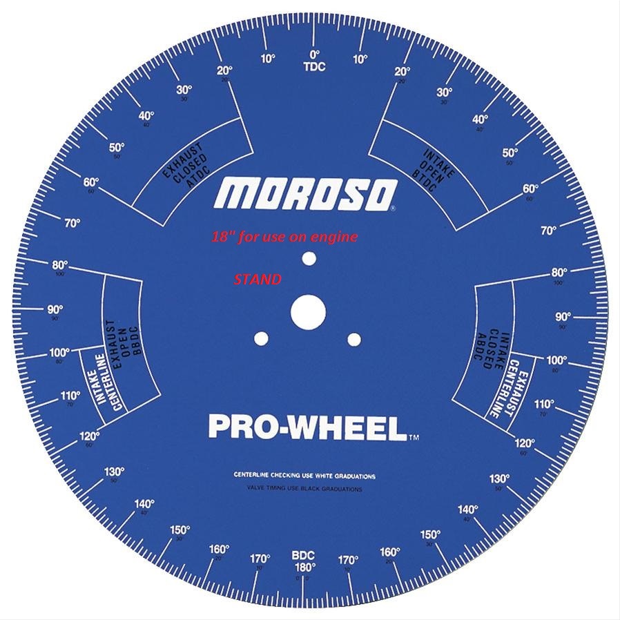
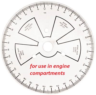
Some degree wheels have multiple scales so that you can make a direct reading of degrees ABDC. If your degree wheel doesn’t have the added scales, count the ten degree marks past 180 degrees (BDC), then add the partial degree remainder to make your final intake closing reading in degrees ABDC. Record the Intake Closing result.
Exhaust Open - Install the dial indicator on the exhaust valve lifter. Rotate the crank and zero the dial when the lifter is on the base circle of the camshaft (all the way down). Turn the crank slowly clockwise until the dial indicator shows that the exhaust lifter has risen to the checking height of .006. Record the degrees shown on the degree wheel.
Again, if your degree wheel doesn’t have multiple scales, count the ten degree marks from 180 degrees to your degree mark to get your exhaust valve open reading in degrees BBDC. Record that measurement.
Exhaust Lobe Lift – Rotate the crank slowly clockwise. The reading on the dial indicator will increase steadily as the lifter rises. When the dial reading begins to decrease, rotate the crank back and forth until you find the highest reading. Be sure to count the revolutions of the dial, each revolution is equal to .100, add the number of revolutions (times .100) to the reading on the dial at highest point on the lobe. That is your total lobe lift, record that measurement. Actual lift at the valve you will multiple that number by your rocker arm ratio.
Exhaust Close – Turn the crank slowly clockwise until the dial indicator shows the exhaust lifter is at the checking height of .006 from the fully closed position. Record the degree measurement shown on the wheel.
Step # 6, Correct the Camshaft Phasing:
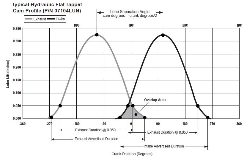
Okay, you have your recorded Valve Opening and Closing Events and Your Lobe Lift. Before you compare your results to the cam card, you must do some math to determine your durations, lobe separation angle, and intake and exhaust centerlines.
Duration is the total time in crankshaft degrees that the valve is open at the specified checking clearance. Total duration is the sum of open location, 180 degrees (distance from TDC to BDC), and the closing location.
Duration = Open degrees + 180 + Closing degrees
My cam (mag280) = 34+180+66=280 seat to seat
My cam both are 280
Calculating Intake lobe centerline – The actual intake and exhaust opening/closing may vary a couple of degrees or more from the cam card specifications. If the measured events are close to specs(within 2 degrees), you can install the cam and correct any error in phasing. This is determined by measuring the distance from the centerline of the intake lobe to TDC (intake centerline). Find the centerline of the intake lobe by dividing the duration (280) by 2. To reference the lobe centerline to TDC, you must subtract the degrees the intake opens BTDC. With my cam it is 34. Here is the formula:
Intake centerline = duration/2 – intake opens degrees BTDC
Example: My cam is Compcams Magnum 280 roller
280/2=140– 34 = 106
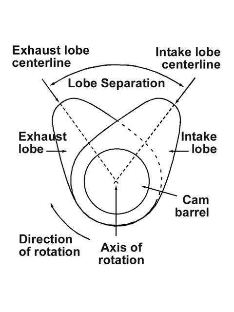
Verify the Lobe Seperation – It is possible that you could have a camshaft that has the lobes ground with the right lift and duration, but was ground with the wrong lobe separation. Before you correct camshaft phasing, it’s important to check the lobe separation. Calculate the exhaust centerline the same way you did with the intake centerline accept use the exhaust closing ATDC. With my cam it is 26. Here is the formula:
Exhaust centerline = duration/2 – exhaust closing degrees ATDC
Example: My cam
280/2 = 140 – 26 = 114
Now, determine the lobe separation using this formula:
Lobe Separation = (intake cl + exhaust cl)/2 = lobe separation
Example: My cam
(106 + 114)/2 = 110
The lobe separation is ground into the cam and cannot be changed, if the specification is wrong by a degree or more it should be replaced. Contact the cam manufacturer for their return policies and information.
If the Intake centerline number is larger than specified on the cam card, it is retarded that number of degrees and has to be advanced the same number of degrees to install at the recommended position. If it is smaller than specified it is advanced that number of degrees and has to be retarded the same number of degrees to install at the recommended position.
Belt drive assembly:
To correct camshaft phasing, the cam drive assembly must be set to advance/retard depending on what your intake centerline measurement actually resulted. To advance turn the cam drive clockwise, to retard turn it counterclockwise. Remember to retorque the bolts on the cam gear.
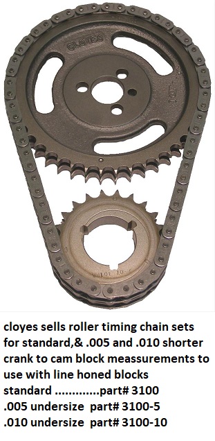
Chain drive:
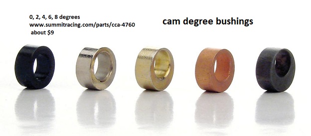
With chain drive there are a few methods to correct your cam phasing. You can buy an offset woodruff key, but the offset weakens the key. You can also buy a crank sprocket that has additional keyways and alignment marks. You can buy a cam degree kit that uses an offset bushing to relocate the cam sprocket. These kits have offset bushings that are color coded and come in one degree increments usually from 0 degrees to 8 degrees. Be sure to follow the installation instructions when using any one of these kits.
When I do the actual degreeing in of my cam I will post pictures as I go through the entire process on my SHP 401. I hope this is helpful to anyone that degrees in their cam.
I did this because the two month mark is coming up for my tenure with the "Reher - Morisson Championship Engine Assembly" book and I am sure "87vette81big" is probably got the shakes by now wanting to get his hands on it.
New racing camshafts have a cam card included that shows the specifications for that camshaft. Degreeing In the cam means verifying that the valve timing and lift are close the specifications printed on the cam card. There are several reasons to degree in a camshaft including:
• Checking for mislabeled camshafts - you may have purchased a camshaft that was mislabeled or placed in the wrong box.
• Verifying valve events - for most applications, it is reasonable to expect that the actual valve opening and closing events are within two degrees of the specifications printed on the cam card and within a few thousandths of the listed lobe lift.
• Checking camshaft phasing - the actual lift and duration may be correct, but the camshaft phasing may be wrong if the sprocket locating dowel is positioned incorrectly. This doesn’t necessarily mean that you must return the camshaft – you may be able to correct the phasing problem. Also, racers and engine builders sometimes find that a particular camshaft works better if it is advanced or retarded a degree or two from the manufacturer’s recommended location.
These are the steps for degreeing-in a camshaft:
1. Install the camshaft.
2. Install the crank, piston & rod assembly, and cam drive assembly
3. Mount and adjust the degree wheel & pointer.
4. Install #1 lifters and dial indicator.
5. Determine the valve opening location, lobe lift, & valve closing location.
6. Calculate & correct the camshaft phasing.
Step #1 , Install the Camshaft:
Apply oil to the cam journals and lobes. Rotate and slide the camshaft into the block. Support and rotate the camshaft as you install it.
Step #2, Install the Crank, Piston & Rod Assembly, and Cam Drive Assembly:
Clean the engine block and crankshaft. Lubricate the main bearings and install the crankshaft. Lubricate and install the main caps, then tighten the bolts or nuts enough to seat the caps. Apply some motor oil on the #1 cylinder wall, and then stabilize the the #1 piston in the bore by wrapping the ring grooves with an even layer of masking tape. Install the piston & rod assembly with rod bearings. Lubricate and snug the rod cap enough to seat it.
Install the front plate and cam thrust hardware with two nuts. Follow the instructions supplied with your cam drive kit. If a thrust plate is used, be sure to check the installed thrust clearance (end play). Set up a dial indicator and push the cam as far as it will go in one direction. Zero the dial, and push the cam the opposite way. The dial will read the cam thrust clearance. Make this measurement several times to be sure it is repeatable and accurate.
Install the crank sprocket or pulley, chain or belt, and cam sprocket or pulley as a unit. Install with pips on both gears or pulleys at the standard “0” alignment marks. Some drive assemblies have other markings for phasing the cam, use the standard setting.
Step #3, Mount and Adjust the Degree Wheel & Pointer:
A degree wheel is a round plate that has degree marks to 180 degrees on either side of TDC and/or for all 360 degrees of crankshaft rotation. Most degree wheels mount to a crank turning socket. Install the socket first, and tighten the set screw. Be sure the woodruff key is in place and that you are using the correct socket. Install the degree wheel on the crank turning socket and tighten the knurled nut securely. Attach a pointer to a fixed location on the block.
To adjust the degree wheel, rotate the until the #1 piston is at TDC. Move the pointer or degree wheel so that the reading is at zero degrees.
NOTE: Piston movement slows down significantly near TDC. This effect is sometimes referred to as piston dwell. Near the top, a degree or two of crankshaft rotation makes very little measurable difference in piston location. This makes it more difficult to determine when the #1 piston is exactly at TDC.
To overcome errors related to piston dwell, find TDC by using a standard piston checking depth. Position the #1 piston so that it is down in the bore an exact distance both before and after TDC. Then rotate the crankshaft until it is exactly halfway between those locations.
One way to create a checking depth is by using a piston stop. A piston stop is a metal bar that bolts across the block deck and mechanically stops piston travel. Some builders use them, but using a dial indicator with the piston stop to find the checking depth will provide you with a more accurate TDC adjustment. It also eliminates the chance of denting the soft aluminum piston.
First, you must make a rough TDC adjustment. Mount the dial indicator on the deck bridge (piston stop) and position it over the #1 piston. The piston rocks on its pin, so apply pressure in one direction so that you have repeatable readings. Use a long bar to engage the crank turning socket, and rotate the crankshaft until you find the high point in piston travel (TDC). Zero the dial indicator, then adjust the degree wheel or bend the pointer to required to indicate zero degrees (TDC).
Step #4, Install # 1 Lifters and Dial Indicator:
Lubricate the lifters, and slide them into the lifter bores for the # 1 cylinder. If the lifters are roller tappets, be sure to install the link bar that prevents lifter rotation.
Identify the # 1 intake lifter. If the pistons have valve reliefs, look for the lifter that corresponds to the larger (intake) valve relief on the piston. You can also determine the order of lifter bores by inspecting the valve layout on the cylinder head.
Mount the dial indicator so that it is in straight contact with the # 1 lifter. Rotate the crankshaft, and adjust the dial so it reads zero when the lifter is all the way down (on the base circle).
You are set up now and ready to degree in your cam.
Step # 5, Determine Valve Opening Location, Lift, & Closing Locations:
The specifications are on the cam card that is shipped with your camshaft, have it handy to compare with your findings.
NOTE: Due to the slack in timing chains or belts, you must always approach locations when degreeing – in the cam by turning the crankshaft clockwise, (the same direction it rotates when the engine is running). If you turn the crank too far, turn it back some distance, and get a “running start” at it again with a clockwise rotation. This ensures the accuracy of the your degree measurements. The checking height may vary, you may want seat to seat measurements in which case the checking height will be .006, or you can use a checking height of .050. For general purposes I am going to use .006(seat to seat). You can still degree at both checking heights to verify all the specs on your cam card.
Intake Open – Turn the crank clockwise until the dial indicator shows that the intake lifter has risen .006 checking height shown on the cam card. Record the degrees BTDC (before TDC) indicated on the wheel.
Intake Lobe Lift – Turn the crank slowly clockwise. The reading on the dial will increase steadily as the lifter rises. When the dial reading begins to decrease, rotate the crank back and forth until you find the highest reading. Be sure to count the full revolutions of the dial, each revolution is equal to .100, add the number of revolutions (times .100) to the reading on the dial at the highest point on the lobe. That is your total lobe lift, record that measurement. Actual lift at the valve you will multiple that number by your rocker arm ratio.
Intake Close – First, turn the crank slowly clockwise until the dial indicator shows that the intake lifter is at the check height of .006 from fully closed position. If you pass the location and reach the base circle (zero dial reading), turn the crank counter clockwise beyond the .006 reading, and approach it slowly in a clockwise direction.
Some degree wheels have multiple scales so that you can make a direct reading of degrees ABDC. If your degree wheel doesn’t have the added scales, count the ten degree marks past 180 degrees (BDC), then add the partial degree remainder to make your final intake closing reading in degrees ABDC. Record the Intake Closing result.
Exhaust Open - Install the dial indicator on the exhaust valve lifter. Rotate the crank and zero the dial when the lifter is on the base circle of the camshaft (all the way down). Turn the crank slowly clockwise until the dial indicator shows that the exhaust lifter has risen to the checking height of .006. Record the degrees shown on the degree wheel.
Again, if your degree wheel doesn’t have multiple scales, count the ten degree marks from 180 degrees to your degree mark to get your exhaust valve open reading in degrees BBDC. Record that measurement.
Exhaust Lobe Lift – Rotate the crank slowly clockwise. The reading on the dial indicator will increase steadily as the lifter rises. When the dial reading begins to decrease, rotate the crank back and forth until you find the highest reading. Be sure to count the revolutions of the dial, each revolution is equal to .100, add the number of revolutions (times .100) to the reading on the dial at highest point on the lobe. That is your total lobe lift, record that measurement. Actual lift at the valve you will multiple that number by your rocker arm ratio.
Exhaust Close – Turn the crank slowly clockwise until the dial indicator shows the exhaust lifter is at the checking height of .006 from the fully closed position. Record the degree measurement shown on the wheel.
Step # 6, Correct the Camshaft Phasing:
Okay, you have your recorded Valve Opening and Closing Events and Your Lobe Lift. Before you compare your results to the cam card, you must do some math to determine your durations, lobe separation angle, and intake and exhaust centerlines.
Duration is the total time in crankshaft degrees that the valve is open at the specified checking clearance. Total duration is the sum of open location, 180 degrees (distance from TDC to BDC), and the closing location.
Duration = Open degrees + 180 + Closing degrees
My cam (mag280) = 34+180+66=280 seat to seat
My cam both are 280
Calculating Intake lobe centerline – The actual intake and exhaust opening/closing may vary a couple of degrees or more from the cam card specifications. If the measured events are close to specs(within 2 degrees), you can install the cam and correct any error in phasing. This is determined by measuring the distance from the centerline of the intake lobe to TDC (intake centerline). Find the centerline of the intake lobe by dividing the duration (280) by 2. To reference the lobe centerline to TDC, you must subtract the degrees the intake opens BTDC. With my cam it is 34. Here is the formula:
Intake centerline = duration/2 – intake opens degrees BTDC
Example: My cam is Compcams Magnum 280 roller
280/2=140– 34 = 106
Verify the Lobe Seperation – It is possible that you could have a camshaft that has the lobes ground with the right lift and duration, but was ground with the wrong lobe separation. Before you correct camshaft phasing, it’s important to check the lobe separation. Calculate the exhaust centerline the same way you did with the intake centerline accept use the exhaust closing ATDC. With my cam it is 26. Here is the formula:
Exhaust centerline = duration/2 – exhaust closing degrees ATDC
Example: My cam
280/2 = 140 – 26 = 114
Now, determine the lobe separation using this formula:
Lobe Separation = (intake cl + exhaust cl)/2 = lobe separation
Example: My cam
(106 + 114)/2 = 110
The lobe separation is ground into the cam and cannot be changed, if the specification is wrong by a degree or more it should be replaced. Contact the cam manufacturer for their return policies and information.
If the Intake centerline number is larger than specified on the cam card, it is retarded that number of degrees and has to be advanced the same number of degrees to install at the recommended position. If it is smaller than specified it is advanced that number of degrees and has to be retarded the same number of degrees to install at the recommended position.
Belt drive assembly:
To correct camshaft phasing, the cam drive assembly must be set to advance/retard depending on what your intake centerline measurement actually resulted. To advance turn the cam drive clockwise, to retard turn it counterclockwise. Remember to retorque the bolts on the cam gear.
Chain drive:
With chain drive there are a few methods to correct your cam phasing. You can buy an offset woodruff key, but the offset weakens the key. You can also buy a crank sprocket that has additional keyways and alignment marks. You can buy a cam degree kit that uses an offset bushing to relocate the cam sprocket. These kits have offset bushings that are color coded and come in one degree increments usually from 0 degrees to 8 degrees. Be sure to follow the installation instructions when using any one of these kits.
When I do the actual degreeing in of my cam I will post pictures as I go through the entire process on my SHP 401. I hope this is helpful to anyone that degrees in their cam.
I did this because the two month mark is coming up for my tenure with the "Reher - Morisson Championship Engine Assembly" book and I am sure "87vette81big" is probably got the shakes by now wanting to get his hands on it.