yes reading thru ALL the info,
is well worth the time and effort if your serious about having a killer combo,
(DON,T IGNORE SUB LINKS THOSE CONTAIN A WEALTH OF INFO)
after all, if you don,t understand whats going on,
how can you improve or correct the procedure or efficiency, of the components you've selected, or want to use., and there's a great deal of info in the links below that you will need to know later and refer back to frequently about duration, lobe center angles etc., info that will be critical to understanding engine function and power levels
if you spend several hours here, reading links it will be time well spent
your bound to notice I install links to useful info in most threads,
now obviously not all the info, posted in all threads will be helpful in all cases,
but you'll eventually come to realize the value of reading thru the info links.
there's a great deal of useful info, in those links
info that you might think is useless to you now, but you'll be amazed at the number of times in the future your going to say to yourself...., damn! I remember reading something about that, now where was that posted, and a brief search will turn up your info!, info you swore at the time was a waste of your time to read thru, I know that's been very common for me and I'm sure it will be for those guys that really want to learn how and why things work!.
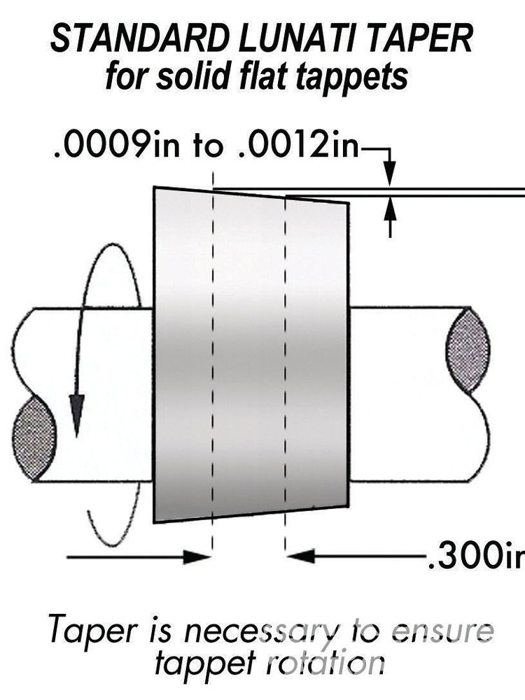
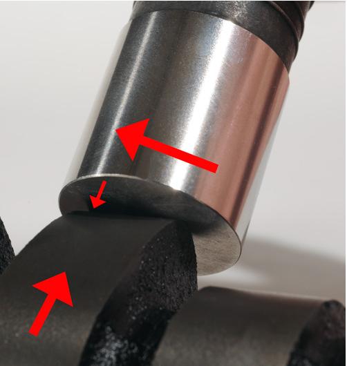
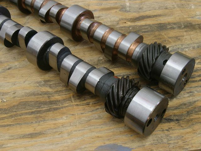
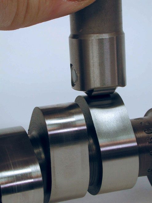
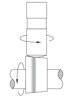
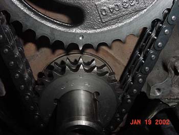
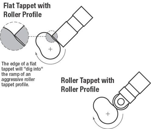
the slight bevel on the cam lobe and the slight convex surface on the lifter base in combination with the lobe center-line being slightly offset from the blocks lifter bore results in the lifter rotating in its bores as the lobe rotates under the lifter base
http://auto.howstuffworks.com/camshaft1.htm
http://www.wallaceracing.com/cambasics.htm
http://www.tildentechnologies.com/Cams/CamPerformance.html
http://www.circletrack.com/techarticles ... ation.html
http://www.tildentechnologies.com/Cams/CamSprings.html
http://www.classicinlines.com/select_cam.asp
http://www.popularhotrodding.com/tech/0 ... index.html
http://www.thirdgen.org/sbc-camshafts-primer
viewtopic.php?f=44&t=3097&p=8240#p8240
http://www.auto-ware.com/combust_bytes/camspecs.html
http://www.chevyhiperformance.com/techa ... index.html
http://www.chevyhiperformance.com/techa ... index.html
viewtopic.php?f=52&t=1070
http://www.webcamshafts.com/pages/cam_glossary.html
viewtopic.php?f=56&t=495
http://www.popularhotrodding.com/tech/0 ... index.html
http://www.geocities.com/fordracing68/cam.html
http://www.crower.com/valve-timing-chart
viewtopic.php?f=52&t=727
http://www.popularhotrodding.com/tech/1 ... index.html
http://www.lt1howto.com/articles/camshafts.htm
http://www.chevyhiperformance.com/tech/ ... index.html
http://autospeed.com/cms/A_108682/printArticle.html
http://members.uia.net/pkelley2/Overlap.html
http://69.20.53.62/faq_valvetrain.php
viewtopic.php?f=52&t=1070
viewtopic.php?f=52&t=1477
viewtopic.php?f=52&t=2926
viewtopic.php?f=52&t=480
viewtopic.php?f=52&t=71&p=89#p89
http://www.popularhotrodding.com/tech/0 ... index.html
http://www.streetracersonline.com/articles/camshafts/
http://www.compcams.com/Community/Artic ... 2026144213
http://victorylibrary.com/mopar/cam-tech-c.htm
http://www.auto-ware.com/combust_bytes/camspecs.html
http://www.scribd.com/doc/11838084/Unde ... afts-terms
viewtopic.php?f=52&t=796
http://tru-442.tripod.com/camselect.htm
http://www.chevyhiperformance.com/techa ... index.html
http://www.projectlt10.com/content/modu ... .php?id=12
http://www.tighecams.com.au/correct-camshaft.htm

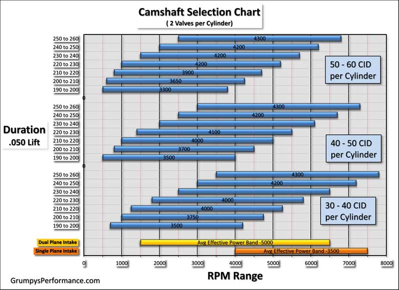
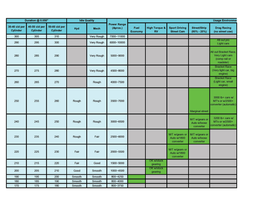
this charts based on a 350-383 chevy or similar size engine, but its a good rought guide on most engines under 400cid displacement on matching the durration to the intender operational rpm band
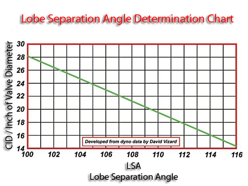
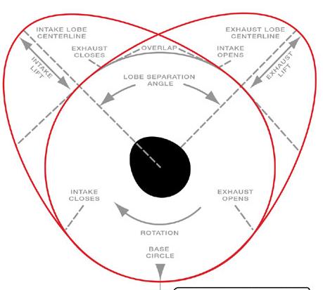
LOBE SEPARATION ANGLE
Above 114 Deg. = Extremely Wide
114-112 Deg. = Wide
112-110 Deg. = Moderately Wide
110-108 Deg. = Moderate
108-106 Deg. = Moderately Tight
106-104 Deg. = Tight
Below 104 Deg. = Extremely Tight
VARYING LOBE SEPARATION ANGLE
Tighten.................................................Widen
Moves Torque to Lower RPM.................Raise Torque to Higher RPM
Increases Maximum Torque..................Reduces Maximum Torque
Narrow Power Band..............................Broadens Power Band
Builds Higher Cylinder Pressure............Reduce Maximum Cylinder Pressure
Increase Chance of Engine Knock.........Decrease Chance of Engine Knock.
Increase Cranking Compression...........Decrease Cranking Compression
Increase Effective Compression............Decrease Effective Compression
Idle Vacuum is Reduced........................Idle Vacuum is Increased
Idle Quality Suffers...............................Idle Quality Improves
Open Valve-Overlap Increases.............Open Valve-Overlap Decreases
Closed Valve-Overlap Increases...........Closed Valve-Overlap Decreases
Natural EGR Effect Increases................Natural EGR Effect is Reduced
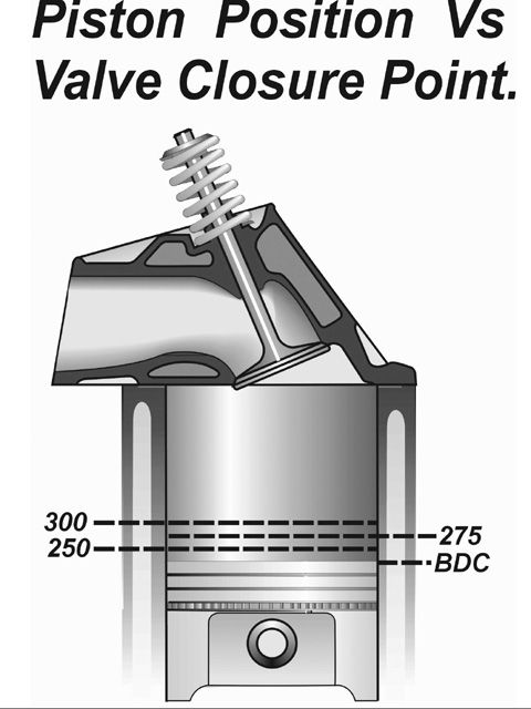
Decreases Piston-to-Valve Clearance...Increases Piston-to-Valve Clearance
ADVANCING / RETARDING CAM TIMING
KEEP IN MIND MANY CAMS ARE FACTORY SET UP TO BE 4 DEGREES ADVANCED if INSTALLED DOT-TO-DOT
ADVANCING.
Begins Intake Event Sooner........................
Open Intake Valve Sooner..........................
Builds More Low-End Torque.......................
Decrease Piston-Intake Valve Clearance....
Increase Piston-Exhaust Valve Clearance...
RETARDING
Delays Intake Event Closes Intake
Keeps Intake Valve Open Later
Builds More High-End Power
Increase Piston-Intake Valve Clearance
Decrease Piston-Exhaust Valve Clearance

http://www.webcamshafts.com/pages/cam_glossary.htm...
Lobe Lift- Total difference from base circle ("0" reference value) to maximum displacement height of the lobe, usually expressed in thousandths of an inch (.433").
Base Circle- Region of the lobe that is not supposed to have any lift, or the reference starting point. Base Circle diameter is also measured for calculating stress loads and determining how the lobe duration will change during grinding.
Lash Ramp- Usually defined as the lash region, or the event that occurs between the first movement of the lifter and the point where valve movement is supposed to start.
Ramp- Different cam designers have different versions of where they define the beginning or end of the ramp, some look at the maximum acceleration point, some the full POSITIVE portion of the acceleration pulse. There is no consensus on what defines the "ramp", just that it is the opening or closing portion of the lobe and not the nose region.
Nose- The upper portion of the lobe, mostly defined by the NEGATIVE portion of the acceleration curve.
Velocity- Rate of change in LIFT, or speed of the lifter. Usually expressed as lift/degree (.00735"/deg). The velocity number is usefull in determining the maximum speed that a flat tappet lifter may acheive with a certain diameter. An example is speed limit like on the highway or your rev limiter of the engine, both limit how fast you can go.
Acceleration- Rate of change in VELOCITY, usually expressed as lift/deg 2 (.00038"/deg 2 ). High acceleration rates place greater loads on valvetrain components, but get the valve open or closed faster usually leading to more power. Lower acceleration rates are easier on components, but usually yield lower power. An example would be to think of dropping the clutch at high rpm in your vehicle, as opposed to letting the clutch out gently at a low rpm and then standing on the gas.
Jerk- Rate of change in ACCELERATION, expressed in lift/deg 3 (.00003/deg 3 ). High jerk values mean that the acceleration rate is changing rapidly, usually an indication of a cam that is noisy to the ear, and probably harder on valvetrain parts than either the peak acceleration or velocity rates would indicate. An example would be to think of accelerating your car (as in the previous definition) over some railroad tracks instead of a smooth road. These kind of quick load reversals are just as damaging to valvetrain as they are to your drivetrain in similar circumstances.
Snap- Believe it or not, rate of change in JERK is sometimes measured. This measurement is in lift/deg 4 , which is not easy to derive from data taken from cam measurements. This is usually looked at during the design stage, where the equations being used are in 7 to 8 place accuracy (.00000001"), nearly impossible to actually measure on a finished product.
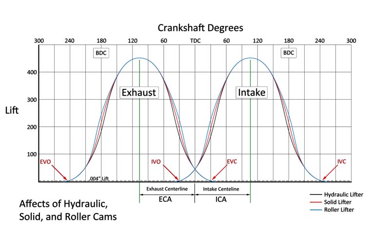

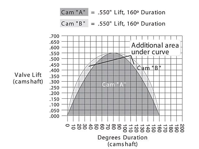
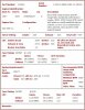
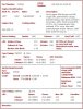
cam duration is usually listed on your cam spec card at .004-.006 lift OR/AND at .050 lift so you can compare cams
advertised duration is basically is measured from valve seat lift off to valve seat re-seating
.050 lift is from the time the valves 50 thousands off the seat until its back to within 50 thousands of re-seating
because the ramp intensity varys with the lobe design the .050 lift tends to be a slightly more valid means to compare similar cams
heres three cam cards notice the advertised duration always exceeds the .050 lift listed duration
you should also keep in mind that a roller cam valve train with the same lift and duration can provide a good deal more port flow and resulting power.
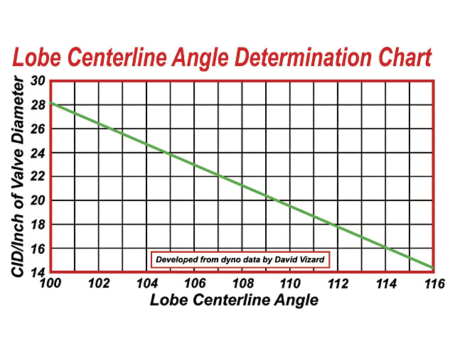
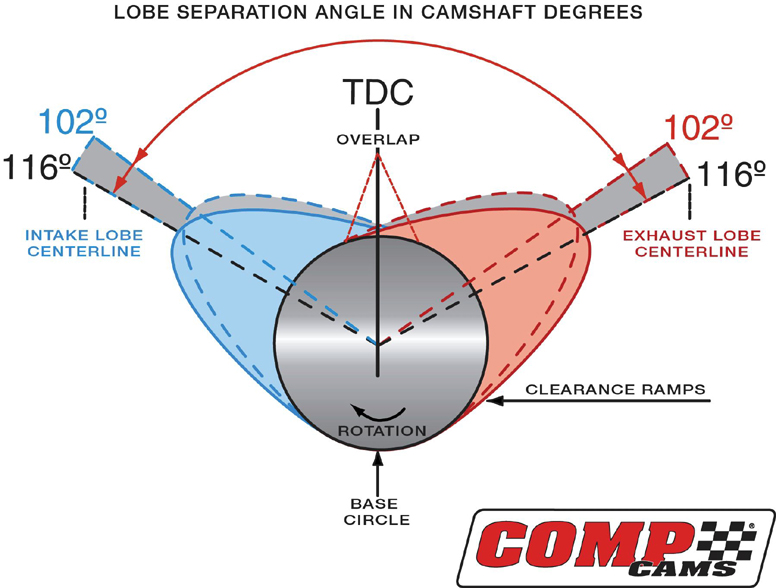
First Id point out that nearly everyone occasionally confuses or at least makes the mistake of using the wrong abbreviation, (LSA, and LCA) these are terms,that are almost, at least in many discussions interchangeable. which they are not.
LSA =LOBE SEPARATION ANGLE ........
LSA is ground into the cam during manufactured, and can,t change,
LCA =(LOBE CENTER ANGLES)remember lobe center angles can be changed thru indexing the cam when degreeing it in
viewtopic.php?f=52&t=1070
viewtopic.php?f=52&t=480
viewtopic.php?f=52&t=2782&p=7215&hilit=+overlap#p7215
viewtopic.php?f=52&t=90
viewtopic.php?f=52&t=2782&p=7433&hilit=+overlap#p7433
is well worth the time and effort if your serious about having a killer combo,
(DON,T IGNORE SUB LINKS THOSE CONTAIN A WEALTH OF INFO)
after all, if you don,t understand whats going on,
how can you improve or correct the procedure or efficiency, of the components you've selected, or want to use., and there's a great deal of info in the links below that you will need to know later and refer back to frequently about duration, lobe center angles etc., info that will be critical to understanding engine function and power levels
if you spend several hours here, reading links it will be time well spent
your bound to notice I install links to useful info in most threads,
now obviously not all the info, posted in all threads will be helpful in all cases,
but you'll eventually come to realize the value of reading thru the info links.
there's a great deal of useful info, in those links
info that you might think is useless to you now, but you'll be amazed at the number of times in the future your going to say to yourself...., damn! I remember reading something about that, now where was that posted, and a brief search will turn up your info!, info you swore at the time was a waste of your time to read thru, I know that's been very common for me and I'm sure it will be for those guys that really want to learn how and why things work!.
the slight bevel on the cam lobe and the slight convex surface on the lifter base in combination with the lobe center-line being slightly offset from the blocks lifter bore results in the lifter rotating in its bores as the lobe rotates under the lifter base
http://auto.howstuffworks.com/camshaft1.htm
http://www.wallaceracing.com/cambasics.htm
http://www.tildentechnologies.com/Cams/CamPerformance.html
http://www.circletrack.com/techarticles ... ation.html
http://www.tildentechnologies.com/Cams/CamSprings.html
http://www.classicinlines.com/select_cam.asp
http://www.popularhotrodding.com/tech/0 ... index.html
http://www.thirdgen.org/sbc-camshafts-primer
viewtopic.php?f=44&t=3097&p=8240#p8240
http://www.auto-ware.com/combust_bytes/camspecs.html
http://www.chevyhiperformance.com/techa ... index.html
http://www.chevyhiperformance.com/techa ... index.html
viewtopic.php?f=52&t=1070
http://www.webcamshafts.com/pages/cam_glossary.html
viewtopic.php?f=56&t=495
http://www.popularhotrodding.com/tech/0 ... index.html
http://www.geocities.com/fordracing68/cam.html
http://www.crower.com/valve-timing-chart
viewtopic.php?f=52&t=727
http://www.popularhotrodding.com/tech/1 ... index.html
http://www.lt1howto.com/articles/camshafts.htm
http://www.chevyhiperformance.com/tech/ ... index.html
http://autospeed.com/cms/A_108682/printArticle.html
http://members.uia.net/pkelley2/Overlap.html
http://69.20.53.62/faq_valvetrain.php
viewtopic.php?f=52&t=1070
viewtopic.php?f=52&t=1477
viewtopic.php?f=52&t=2926
viewtopic.php?f=52&t=480
viewtopic.php?f=52&t=71&p=89#p89
http://www.popularhotrodding.com/tech/0 ... index.html
http://www.streetracersonline.com/articles/camshafts/
http://www.compcams.com/Community/Artic ... 2026144213
http://victorylibrary.com/mopar/cam-tech-c.htm
http://www.auto-ware.com/combust_bytes/camspecs.html
http://www.scribd.com/doc/11838084/Unde ... afts-terms
viewtopic.php?f=52&t=796
http://tru-442.tripod.com/camselect.htm
http://www.chevyhiperformance.com/techa ... index.html
http://www.projectlt10.com/content/modu ... .php?id=12
http://www.tighecams.com.au/correct-camshaft.htm
this charts based on a 350-383 chevy or similar size engine, but its a good rought guide on most engines under 400cid displacement on matching the durration to the intender operational rpm band
LOBE SEPARATION ANGLE
Above 114 Deg. = Extremely Wide
114-112 Deg. = Wide
112-110 Deg. = Moderately Wide
110-108 Deg. = Moderate
108-106 Deg. = Moderately Tight
106-104 Deg. = Tight
Below 104 Deg. = Extremely Tight
VARYING LOBE SEPARATION ANGLE
Tighten.................................................Widen
Moves Torque to Lower RPM.................Raise Torque to Higher RPM
Increases Maximum Torque..................Reduces Maximum Torque
Narrow Power Band..............................Broadens Power Band
Builds Higher Cylinder Pressure............Reduce Maximum Cylinder Pressure
Increase Chance of Engine Knock.........Decrease Chance of Engine Knock.
Increase Cranking Compression...........Decrease Cranking Compression
Increase Effective Compression............Decrease Effective Compression
Idle Vacuum is Reduced........................Idle Vacuum is Increased
Idle Quality Suffers...............................Idle Quality Improves
Open Valve-Overlap Increases.............Open Valve-Overlap Decreases
Closed Valve-Overlap Increases...........Closed Valve-Overlap Decreases
Natural EGR Effect Increases................Natural EGR Effect is Reduced
Decreases Piston-to-Valve Clearance...Increases Piston-to-Valve Clearance
ADVANCING / RETARDING CAM TIMING
KEEP IN MIND MANY CAMS ARE FACTORY SET UP TO BE 4 DEGREES ADVANCED if INSTALLED DOT-TO-DOT
ADVANCING.
Begins Intake Event Sooner........................
Open Intake Valve Sooner..........................
Builds More Low-End Torque.......................
Decrease Piston-Intake Valve Clearance....
Increase Piston-Exhaust Valve Clearance...
RETARDING
Delays Intake Event Closes Intake
Keeps Intake Valve Open Later
Builds More High-End Power
Increase Piston-Intake Valve Clearance
Decrease Piston-Exhaust Valve Clearance
http://www.webcamshafts.com/pages/cam_glossary.htm...
Lobe Lift- Total difference from base circle ("0" reference value) to maximum displacement height of the lobe, usually expressed in thousandths of an inch (.433").
Base Circle- Region of the lobe that is not supposed to have any lift, or the reference starting point. Base Circle diameter is also measured for calculating stress loads and determining how the lobe duration will change during grinding.
Lash Ramp- Usually defined as the lash region, or the event that occurs between the first movement of the lifter and the point where valve movement is supposed to start.
Ramp- Different cam designers have different versions of where they define the beginning or end of the ramp, some look at the maximum acceleration point, some the full POSITIVE portion of the acceleration pulse. There is no consensus on what defines the "ramp", just that it is the opening or closing portion of the lobe and not the nose region.
Nose- The upper portion of the lobe, mostly defined by the NEGATIVE portion of the acceleration curve.
Velocity- Rate of change in LIFT, or speed of the lifter. Usually expressed as lift/degree (.00735"/deg). The velocity number is usefull in determining the maximum speed that a flat tappet lifter may acheive with a certain diameter. An example is speed limit like on the highway or your rev limiter of the engine, both limit how fast you can go.
Acceleration- Rate of change in VELOCITY, usually expressed as lift/deg 2 (.00038"/deg 2 ). High acceleration rates place greater loads on valvetrain components, but get the valve open or closed faster usually leading to more power. Lower acceleration rates are easier on components, but usually yield lower power. An example would be to think of dropping the clutch at high rpm in your vehicle, as opposed to letting the clutch out gently at a low rpm and then standing on the gas.
Jerk- Rate of change in ACCELERATION, expressed in lift/deg 3 (.00003/deg 3 ). High jerk values mean that the acceleration rate is changing rapidly, usually an indication of a cam that is noisy to the ear, and probably harder on valvetrain parts than either the peak acceleration or velocity rates would indicate. An example would be to think of accelerating your car (as in the previous definition) over some railroad tracks instead of a smooth road. These kind of quick load reversals are just as damaging to valvetrain as they are to your drivetrain in similar circumstances.
Snap- Believe it or not, rate of change in JERK is sometimes measured. This measurement is in lift/deg 4 , which is not easy to derive from data taken from cam measurements. This is usually looked at during the design stage, where the equations being used are in 7 to 8 place accuracy (.00000001"), nearly impossible to actually measure on a finished product.
cam duration is usually listed on your cam spec card at .004-.006 lift OR/AND at .050 lift so you can compare cams
advertised duration is basically is measured from valve seat lift off to valve seat re-seating
.050 lift is from the time the valves 50 thousands off the seat until its back to within 50 thousands of re-seating
because the ramp intensity varys with the lobe design the .050 lift tends to be a slightly more valid means to compare similar cams
heres three cam cards notice the advertised duration always exceeds the .050 lift listed duration
you should also keep in mind that a roller cam valve train with the same lift and duration can provide a good deal more port flow and resulting power.
First Id point out that nearly everyone occasionally confuses or at least makes the mistake of using the wrong abbreviation, (LSA, and LCA) these are terms,that are almost, at least in many discussions interchangeable. which they are not.
LSA =LOBE SEPARATION ANGLE ........
LSA is ground into the cam during manufactured, and can,t change,
LCA =(LOBE CENTER ANGLES)remember lobe center angles can be changed thru indexing the cam when degreeing it in
viewtopic.php?f=52&t=1070
viewtopic.php?f=52&t=480
viewtopic.php?f=52&t=2782&p=7215&hilit=+overlap#p7215
viewtopic.php?f=52&t=90
viewtopic.php?f=52&t=2782&p=7433&hilit=+overlap#p7433
Attachments
Last edited by a moderator: