its well worth reading thru the links posted here carefully
theres at least a few hours of very worth while , and quite useful reading in this thread and links that will prevent you wasting time and money, keep in mind the sub links contain a huge wealth of additional info youll need
what seems to be over-looked in many engine builds is simply the fact you'll almost always DEEPLY regret jumping into the engine build with both feet and waving your check book as you sink ever deeper into piles of parts receipts and machine shop bills, rather than stepping back with a legal pad, and a calculator and listing in minute detail exactly what you want to accomplish, and taking the time and effort too list and check out in detail what each machine shop procedure costs, why its required and how much each components costs, what your options are and how each component will add too or benefit the completed combo (or in some cases cause you time and grief)
stepping back and thinking things through in detail and listing the cost and potential problems and finding the solutions BEFORE you dive into the process may be a lot less fun, but in the long term its sure to cost less and result in a far better finished project!
you might be amazed at what a couple hours research into the subject will do to help you build a much more durable engine, and actually reading thru links and sub-links and asking questions helps a great deal
http://www.engineparts.com/publications/CL77-3-402.pdf
viewtopic.php?f=54&t=3519
http://www.stealth316.com/misc/clevite- ... ooving.pdf
http://kingbearings.com/files/Engine_Be ... erials.pdf
http://www.bracketracer.com/engine/mains/mains.htm
http://garage.grumpysperformance.co...k-after-a-cam-lobe-rod-or-bearings-fail.2919/
http://garage.grumpysperformance.co...oil-passages-and-improved-oil-flow-mods.3834/
viewtopic.php?f=54&t=120&p=150#p150
http://www.circletrack.com/enginetech/c ... ce_basics/
http://engineparts.com/techbulletins/CL77-1-205R.pdf
http://www.bobistheoilguy.com/bearingwe ... alysis.htm
http://www.mahleclevite.com/publications/EB-40-07.pdf
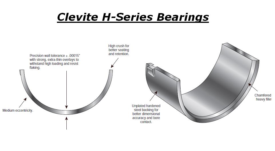
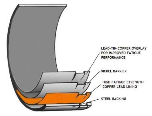
Ive generally found the H-series bearings are the best choice
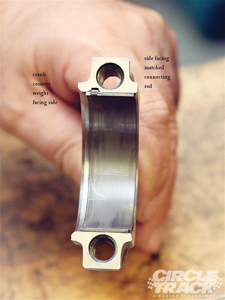
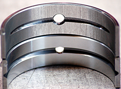
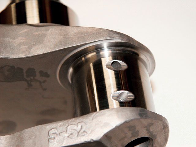
one factor to keep in mind is that rods typically have a side that rides against its matched companion and a side thats BEVELED for clearance on the crank journals radias EXAMPLE
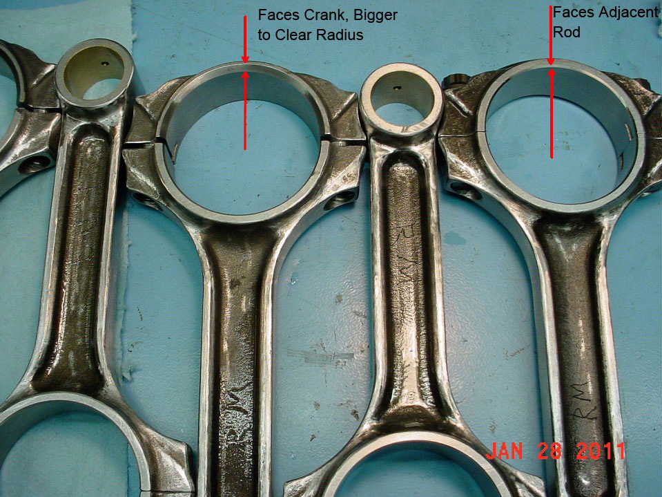
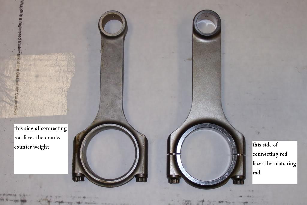
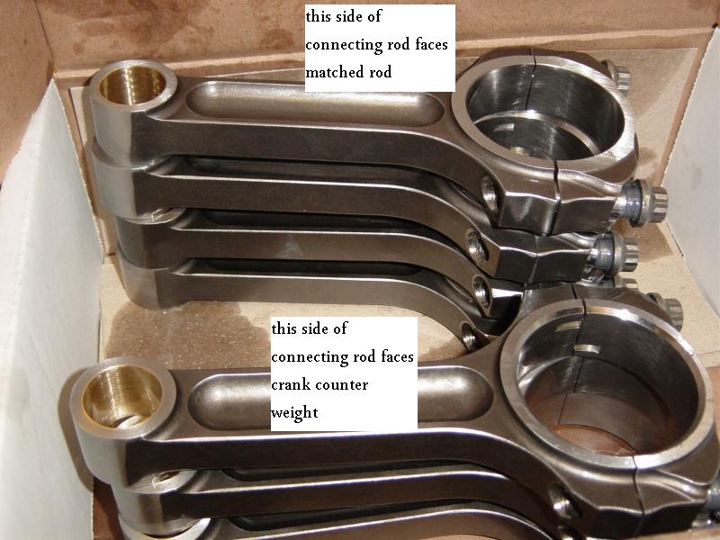
notice the top rods non-beveled side that faces the matching rod is up, but on the lower rod the the beveled side that faces the crank counter weight is up on the lower rod
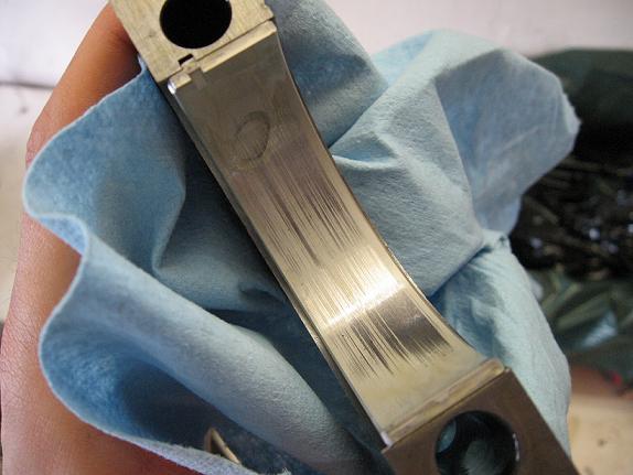
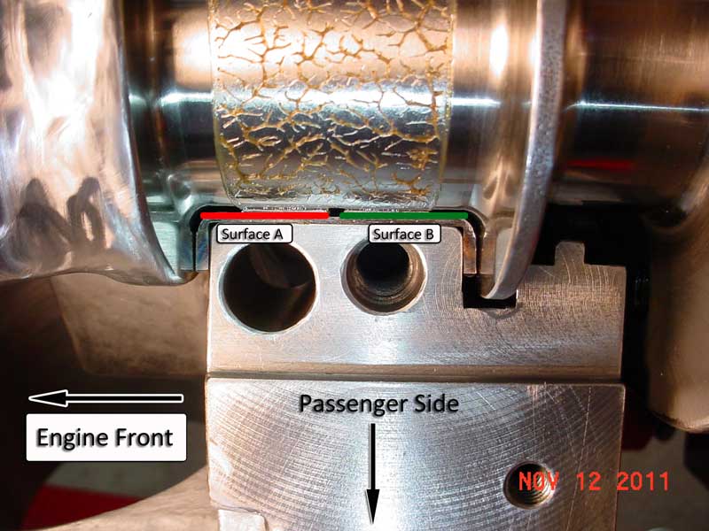
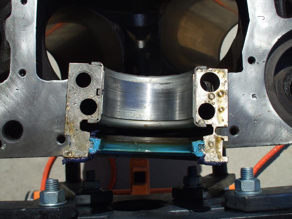
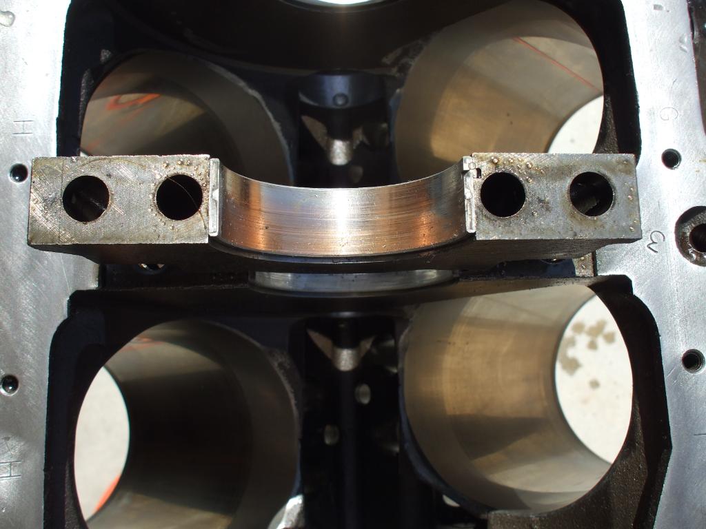
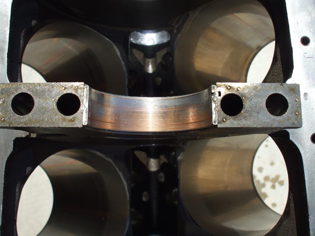
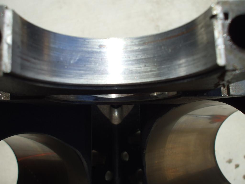
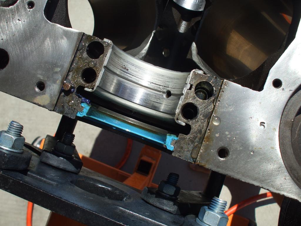
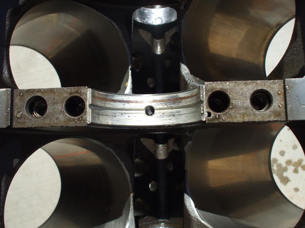
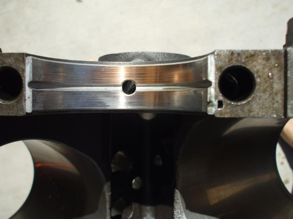
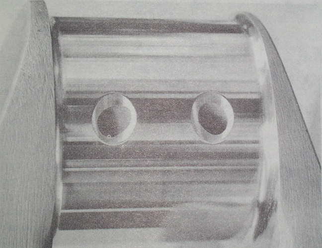
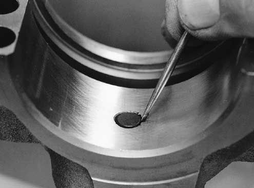
failure to clean out the oil passages in the block and crank journal cross feed oil holes, resulted in trapped debris being flushed out and scoring the bearings during the test fit process in these bearings, an easily avoided but very common screw-up after a cam or bearing fails and your forced to do a ring, cam,lifter, and bearing replacement
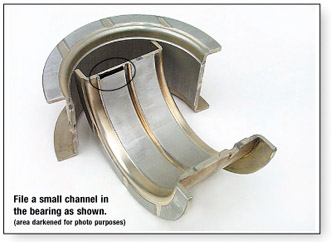
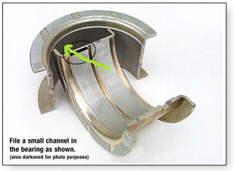
just keep in mind that you'll need to very carefully blend and smooth and carefully clean,the edges of the beveled area where the oil port feeds the bearing surface with some 600 grit sand paper so the oil flows well and theres no edges to cause bearing wear issues or crud left from the process that would get embedded in the bearings.
watch this video
http://www.youtube.com/watch?feature=pl ... dEFGJqpCMY
http://www.enginebuildermag.com/Article ... o_bad.aspx
MORE USEFUL INFO
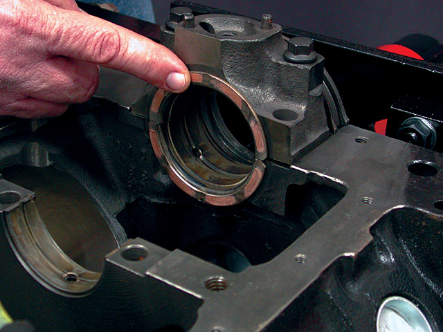
BE 100% SURE that the oil pump bolt or STUD doesn,t protrude past the inner main cap surface , because if it bears on the rear main bearing shell it will almost always result in a quickly failed rear bearing
MAJOR CAUSES OF PREMATURE BEARING FAILURE
Dirt ......................................... 45.4%
Misassembly .......................... 12.8%
Misalignment .......................... 12.6%
Insufficient Lubrication.............11.4%
Overloading .............................. 8.1%
Corrosion ................................ .3.7%
Improper Journal Finish ............ 3.2%
Other ....................................... .2.8%
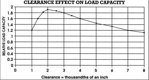
in a properly set up block a pressurized oil film supports the cam and main bearings
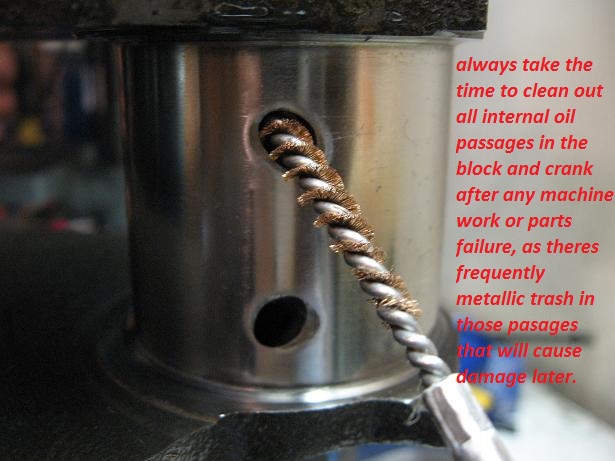
you would most likely be amazed at the metallic crud a few high temp magnets , and shrapnel screens can trap and prevent from getting to your oil pump and bearings, or the amount of crud a decent oil filter traps once its passed thru the oil pump, especially if the oil filters equipped with a strong magnet, but changing your filter and oil on a frequent basis and assembling your engine with the correct clearances helps a great deal, any time you use a block on a new engine build youll need to remove all the oil passage plugs an rod out the oil passages with a rifle bore brush and a high pressure pressure cleaner and replace the gallery plugs, and cam bearings.
if you've had a cam wipe a lobe or a bearing fail its an EXCELLENT IDEA to replace the cam bearings and use a rifle bore brush to remove metallic crud from the blocks internal oil passages because theres an excellent chance they have trapped metallic crud in them
viewtopic.php?f=51&t=1458&p=3265&hilit=shrapnel#p3265
viewtopic.php?f=54&t=120&p=867&hilit=+magnets#p867
viewtopic.php?f=54&t=2187
viewtopic.php?f=54&t=2080
viewtopic.php?f=54&t=65
viewtopic.php?f=54&t=64
http://www.appliedindustrial.com/base.cfm?page_id=3549
from chevy high performance mag


Common Causes of Bearing Failures
There are many causes of bearing damage. It is not always easy to determine the exact cause, but most bearing failures can be attributed to one or more of the following major causes:
Foreign matter: One of the most common sources of trouble in bearings is wear and pitting caused by foreign particles. This could be in the form of dirt, abrasive grit, lint, dust, steel chips, etc.
Improper mounting: Bearings should be mounted with a press fit on the rotating ring. Generally, the shaft rotates and the inner ring is mounted with a press or interference fit.
1. Mounting bearings on shafts by applying blows or pressure to the outer race will usually cause denting (true brinell).
2. Loose shaft fit – rotation of the shaft within the inner ring can produce heat and small loose particles of metal that will eventually get into the bearing, causing wear.
3. Loose housing fit – damage similar to loose shaft fit.
4. Excessive tight fits – (shaft and housing) can cause rings to crack. Usually causes excessive internal preload because of the removal of internal clearance. Causes high operating temperature and premature failure.
5. Out of round housings – usually found in split housings where careful machining is necessary to obtain round housing. Causes localized overloading with abnormal wear on surfaces and retainer pockets. Early fatigue occurs in these areas.
6. Poor finish on the bearing seat – a coarse finish on the bearing seat will soon break down causing a loose fit condition, previously described.
Misalignment: A frequent source of trouble resulting in overheating and separator failure. Common causes are bent shafts, out-of-square shaft shoulders, out-of-square spacers, and out-of-square clamping nuts. Inspection of the raceways will show the ball track veering from one side to the other.
Vibration Brinell (False Brinell): Caused by the rapid movement of the balls in the raceway while the equipment is idle. Rolling elements quickly remove lubrication and, because there is not enough rotation of the bearing, fresh lubricant is not moved back into the spot. This means the bearing is sitting in one spot, devoid of lubrication, and the movement of the rolling elements wears away the metal. The indentations run axially across the races.
Electrical Damage (Fluting): When electric currents pass through a bearing, there is arcing and burning at the points between the races and the rolling elements where the current jumps the air gap. Pitting or cratering of a bearing is caused by relatively large charges of electricity.
A line of small burns along the line of contact of the rolling elements is caused by a low current constantly passing through the bearing. This fluting or grooving is formed on all parts as the current continues to pass through the bearing, and the contact points change as the bearing rotates. The steel melts in the affected zone. Electrical damage will cause early spalling and results in a noisy bearing which will have to be replaced.
Improper Lubrication: Lack of or improper lubrication generally causes overheating or excessive wear in the bearing. These conditions can result from insufficient lubrication, improper lubricants, complete absence of lubrication, or insufficient lubrication due to loss through leakage. Also to be considered is the breakdown of lubricants either by oxidation or exposure to atmospheric conditions.
Fatigue: Fatigue means the fatiguing of the metal in the components of the bearing. It is a result of stress reversals produced when rotating members create flexing of the metal. Fatigue develops due to the magnitude of the load and the number of times it is repeated. Actually, the rolling elements create a wave of metal in front of them as they roll. Thus, the metal in the components is alternately put in tension and then compression. This action eventually results in flaking of the metal.
Corrosion: The finely finished surfaces of ball and roller bearings are readily subject to corrosion by water, acids, and other agents. Corrosion is basically abrasive in nature and will account for excessive or abnormal wear in bearings. Common causes of corrosion include moisture, acid action, poor or broken down greases, poor wrappings, and condensation resulting from excessive temperature reversals.
Defective Sealing: This enables foreign material and contaminants to enter the bearing, causing wear.
High Temperatures: High temperatures frequently cause premature bearing failure, the nature of the failure being predicated on the temperature to which the bearing is raised and the grease with which it is lubricated. Mild temperature elevations may cause grease to bleed which reduces the efficiency of the lubricant. Under increasingly elevated temperature conditions, oxidation causes loss of lubricating elements and the formation of carbon. The carbon thus formed may lock or jam the bearing. High temperatures may also reduce the hardness of the metal causing early failure. High temperatures can cause loss of internal clearance and preloading results. Many bearing failures can be traced to dirt. Cleanliness is always a must.
Storage: Dampness (rust) - store bearings in a dry room.
Viscosity/centistoke
occasionally I get asked questions ,concerning terms or concepts that I assumed were common knowledge. ok lets start with the basics, oil flowing over the moving surfaces in any engine is used too, absorb and transfer heat away from, and separate and prevent physical contact between moving...
garage.grumpysperformance.com
what seems to be over-looked in many engine builds is simply the fact you'll almost always DEEPLY regret jumping into the engine build with both feet and waving your check book as you sink ever deeper into piles of parts receipts and machine shop bills, rather than stepping back with a legal pad, and a calculator and listing in minute detail exactly what you want to accomplish, and taking the time and effort too list and check out in detail what each machine shop procedure costs, why its required and how much each components costs, what your options are and how each component will add too or benefit the completed combo (or in some cases cause you time and grief)
stepping back and thinking things through in detail and listing the cost and potential problems and finding the solutions BEFORE you dive into the process may be a lot less fun, but in the long term its sure to cost less and result in a far better finished project!
you might be amazed at what a couple hours research into the subject will do to help you build a much more durable engine, and actually reading thru links and sub-links and asking questions helps a great deal
http://www.engineparts.com/publications/CL77-3-402.pdf
viewtopic.php?f=54&t=3519
http://www.stealth316.com/misc/clevite- ... ooving.pdf
http://kingbearings.com/files/Engine_Be ... erials.pdf
http://www.bracketracer.com/engine/mains/mains.htm
http://garage.grumpysperformance.co...k-after-a-cam-lobe-rod-or-bearings-fail.2919/
http://garage.grumpysperformance.co...oil-passages-and-improved-oil-flow-mods.3834/
viewtopic.php?f=54&t=120&p=150#p150
http://www.circletrack.com/enginetech/c ... ce_basics/
http://engineparts.com/techbulletins/CL77-1-205R.pdf
http://www.bobistheoilguy.com/bearingwe ... alysis.htm
http://www.mahleclevite.com/publications/EB-40-07.pdf
Ive generally found the H-series bearings are the best choice
one factor to keep in mind is that rods typically have a side that rides against its matched companion and a side thats BEVELED for clearance on the crank journals radias EXAMPLE
notice the top rods non-beveled side that faces the matching rod is up, but on the lower rod the the beveled side that faces the crank counter weight is up on the lower rod
failure to clean out the oil passages in the block and crank journal cross feed oil holes, resulted in trapped debris being flushed out and scoring the bearings during the test fit process in these bearings, an easily avoided but very common screw-up after a cam or bearing fails and your forced to do a ring, cam,lifter, and bearing replacement
just keep in mind that you'll need to very carefully blend and smooth and carefully clean,the edges of the beveled area where the oil port feeds the bearing surface with some 600 grit sand paper so the oil flows well and theres no edges to cause bearing wear issues or crud left from the process that would get embedded in the bearings.
watch this video
http://www.youtube.com/watch?feature=pl ... dEFGJqpCMY
http://www.enginebuildermag.com/Article ... o_bad.aspx
MORE USEFUL INFO
BE 100% SURE that the oil pump bolt or STUD doesn,t protrude past the inner main cap surface , because if it bears on the rear main bearing shell it will almost always result in a quickly failed rear bearing
MAJOR CAUSES OF PREMATURE BEARING FAILURE
Dirt ......................................... 45.4%
Misassembly .......................... 12.8%
Misalignment .......................... 12.6%
Insufficient Lubrication.............11.4%
Overloading .............................. 8.1%
Corrosion ................................ .3.7%
Improper Journal Finish ............ 3.2%
Other ....................................... .2.8%
in a properly set up block a pressurized oil film supports the cam and main bearings
you would most likely be amazed at the metallic crud a few high temp magnets , and shrapnel screens can trap and prevent from getting to your oil pump and bearings, or the amount of crud a decent oil filter traps once its passed thru the oil pump, especially if the oil filters equipped with a strong magnet, but changing your filter and oil on a frequent basis and assembling your engine with the correct clearances helps a great deal, any time you use a block on a new engine build youll need to remove all the oil passage plugs an rod out the oil passages with a rifle bore brush and a high pressure pressure cleaner and replace the gallery plugs, and cam bearings.
if you've had a cam wipe a lobe or a bearing fail its an EXCELLENT IDEA to replace the cam bearings and use a rifle bore brush to remove metallic crud from the blocks internal oil passages because theres an excellent chance they have trapped metallic crud in them
viewtopic.php?f=51&t=1458&p=3265&hilit=shrapnel#p3265
viewtopic.php?f=54&t=120&p=867&hilit=+magnets#p867
viewtopic.php?f=54&t=2187
viewtopic.php?f=54&t=2080
viewtopic.php?f=54&t=65
viewtopic.php?f=54&t=64
http://www.appliedindustrial.com/base.cfm?page_id=3549
from chevy high performance mag
Common Causes of Bearing Failures
There are many causes of bearing damage. It is not always easy to determine the exact cause, but most bearing failures can be attributed to one or more of the following major causes:
Foreign matter: One of the most common sources of trouble in bearings is wear and pitting caused by foreign particles. This could be in the form of dirt, abrasive grit, lint, dust, steel chips, etc.
Improper mounting: Bearings should be mounted with a press fit on the rotating ring. Generally, the shaft rotates and the inner ring is mounted with a press or interference fit.
1. Mounting bearings on shafts by applying blows or pressure to the outer race will usually cause denting (true brinell).
2. Loose shaft fit – rotation of the shaft within the inner ring can produce heat and small loose particles of metal that will eventually get into the bearing, causing wear.
3. Loose housing fit – damage similar to loose shaft fit.
4. Excessive tight fits – (shaft and housing) can cause rings to crack. Usually causes excessive internal preload because of the removal of internal clearance. Causes high operating temperature and premature failure.
5. Out of round housings – usually found in split housings where careful machining is necessary to obtain round housing. Causes localized overloading with abnormal wear on surfaces and retainer pockets. Early fatigue occurs in these areas.
6. Poor finish on the bearing seat – a coarse finish on the bearing seat will soon break down causing a loose fit condition, previously described.
Misalignment: A frequent source of trouble resulting in overheating and separator failure. Common causes are bent shafts, out-of-square shaft shoulders, out-of-square spacers, and out-of-square clamping nuts. Inspection of the raceways will show the ball track veering from one side to the other.
Vibration Brinell (False Brinell): Caused by the rapid movement of the balls in the raceway while the equipment is idle. Rolling elements quickly remove lubrication and, because there is not enough rotation of the bearing, fresh lubricant is not moved back into the spot. This means the bearing is sitting in one spot, devoid of lubrication, and the movement of the rolling elements wears away the metal. The indentations run axially across the races.
Electrical Damage (Fluting): When electric currents pass through a bearing, there is arcing and burning at the points between the races and the rolling elements where the current jumps the air gap. Pitting or cratering of a bearing is caused by relatively large charges of electricity.
A line of small burns along the line of contact of the rolling elements is caused by a low current constantly passing through the bearing. This fluting or grooving is formed on all parts as the current continues to pass through the bearing, and the contact points change as the bearing rotates. The steel melts in the affected zone. Electrical damage will cause early spalling and results in a noisy bearing which will have to be replaced.
Improper Lubrication: Lack of or improper lubrication generally causes overheating or excessive wear in the bearing. These conditions can result from insufficient lubrication, improper lubricants, complete absence of lubrication, or insufficient lubrication due to loss through leakage. Also to be considered is the breakdown of lubricants either by oxidation or exposure to atmospheric conditions.
Fatigue: Fatigue means the fatiguing of the metal in the components of the bearing. It is a result of stress reversals produced when rotating members create flexing of the metal. Fatigue develops due to the magnitude of the load and the number of times it is repeated. Actually, the rolling elements create a wave of metal in front of them as they roll. Thus, the metal in the components is alternately put in tension and then compression. This action eventually results in flaking of the metal.
Corrosion: The finely finished surfaces of ball and roller bearings are readily subject to corrosion by water, acids, and other agents. Corrosion is basically abrasive in nature and will account for excessive or abnormal wear in bearings. Common causes of corrosion include moisture, acid action, poor or broken down greases, poor wrappings, and condensation resulting from excessive temperature reversals.
Defective Sealing: This enables foreign material and contaminants to enter the bearing, causing wear.
High Temperatures: High temperatures frequently cause premature bearing failure, the nature of the failure being predicated on the temperature to which the bearing is raised and the grease with which it is lubricated. Mild temperature elevations may cause grease to bleed which reduces the efficiency of the lubricant. Under increasingly elevated temperature conditions, oxidation causes loss of lubricating elements and the formation of carbon. The carbon thus formed may lock or jam the bearing. High temperatures may also reduce the hardness of the metal causing early failure. High temperatures can cause loss of internal clearance and preloading results. Many bearing failures can be traced to dirt. Cleanliness is always a must.
Storage: Dampness (rust) - store bearings in a dry room.
Last edited by a moderator: