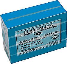
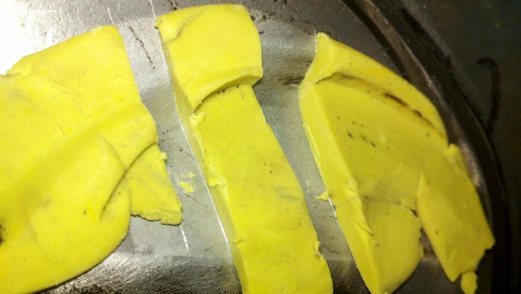
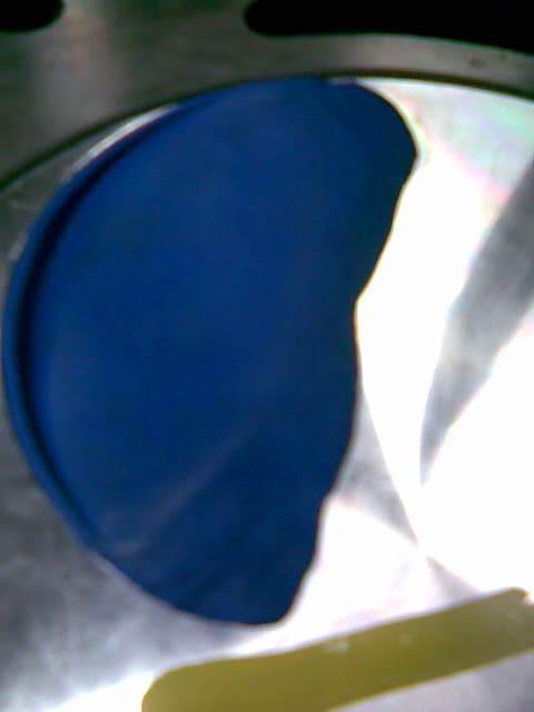
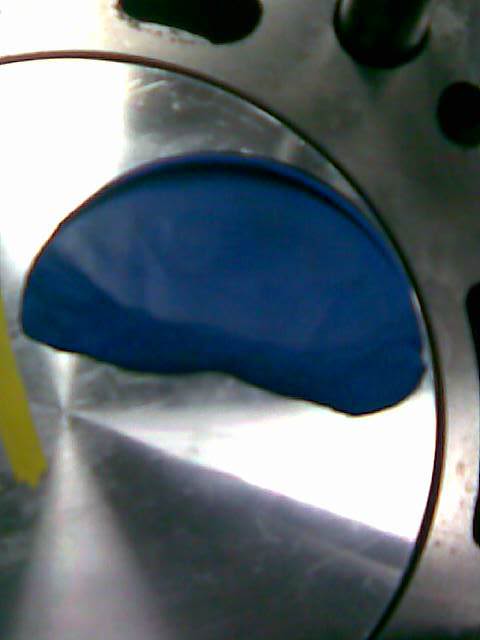
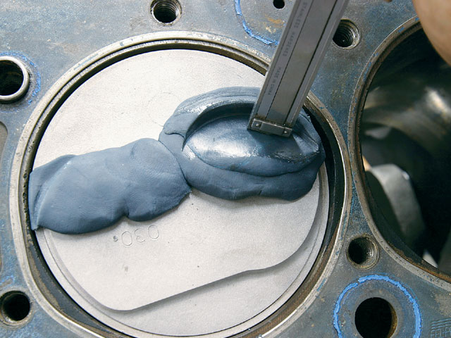
I still use the strips of modeling clay about 1" square and .2" (two tenths thick) but one thing everyone forgot to mention so far is that you need to spray the piston and valve and clay strips with WD-40 to ensure the clay does not stick to any parts, otherwise the clay will tend to stick to the valve and piston allowing them to push the clay between them during the compression of its surface by the valve (exactly what its there for) and PULL ON THE SURFACE of the clay as the valve moves away during separation (because the clay tends to stick ever so slightly as the parts pull away from each other if you don,t)which tends to give a false slightly greater than correct clearance measurement
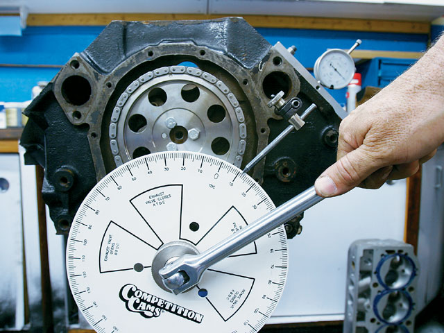
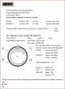
The ex will be closest between 20 & 5° BTC & the intake 5-20° ATC
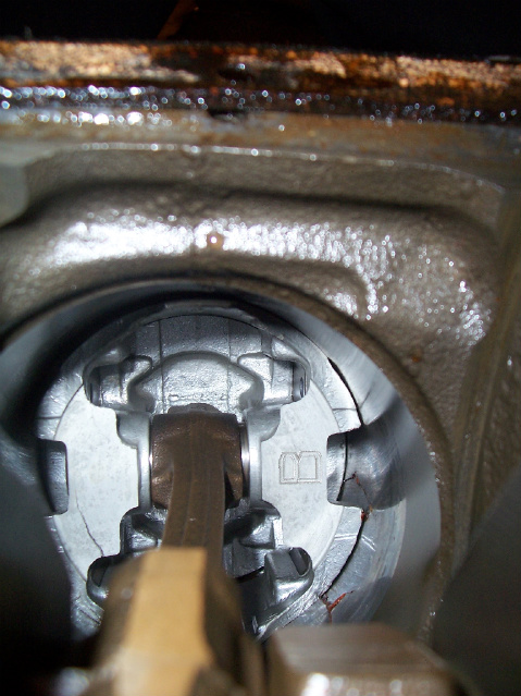
Exhaust side
Rotate the engine between 20 & 5 degrees BTC & find the closest point
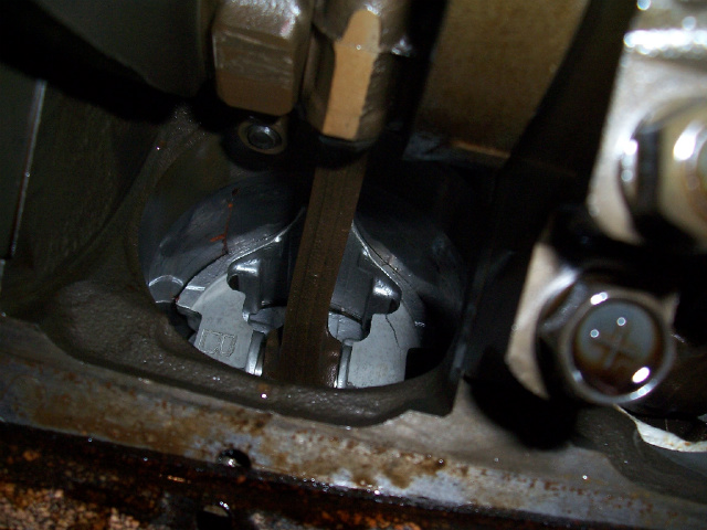
Intake
Rotate the engine between 5 & 20 degrees ATC & find the closest point
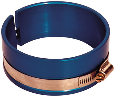
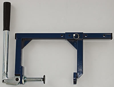
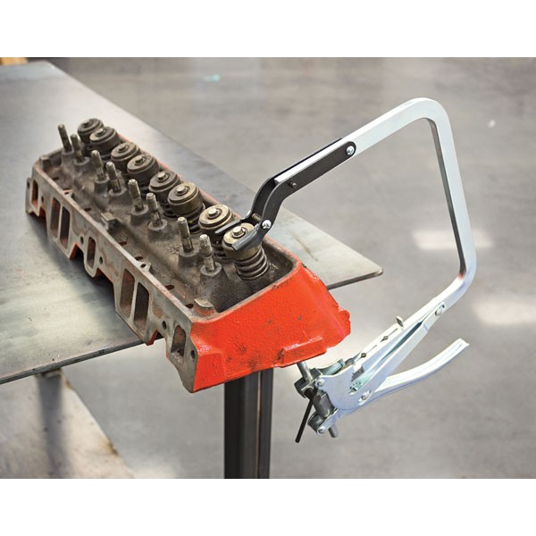
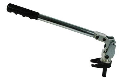
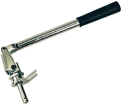
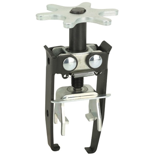
http://www.summitracing.com/parts/pro-66830

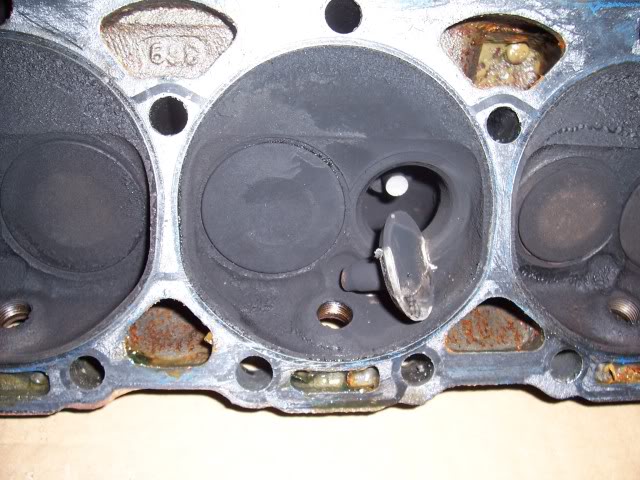
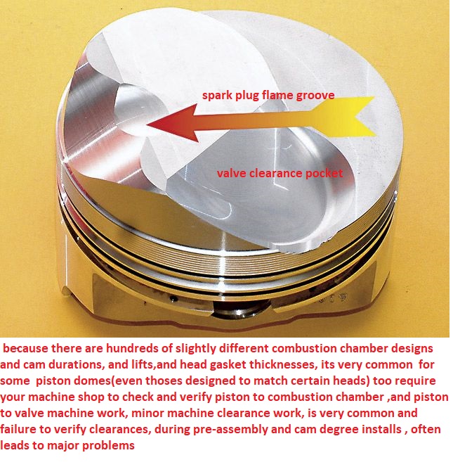
Any decent, experienced machine shop can measure your cylinder heads combustion chamber,
and calculate the required clearances after measuring your heads combustion chamber, and then do the correct machine work on your piston domes,
machining the domes for adequate,spark plug,clearance,
this is a very common issue and easily resolved,
most people tend to tell me Im wrong about that use of WD40 spray on the clay, until they try it both ways... yeah the difference is usually minor but five to 10 thousands difference is not rare if the parts are clean and dry versus sprayed with an oil mist

Id be a whole lot happier on a 6000rpm-7000rpm plus engine build, up if my piston to valve clearance, on my engine was .100-.120 inch minimum, clearance even if it required machining the piston valve pocket depth about .060 (don,t forget the valve edge to valve pocket edge clearance)
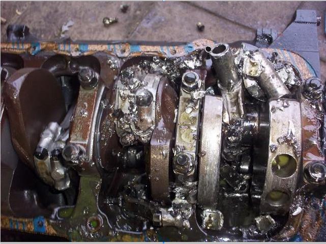
GET THE CLEARANCES WRONG OR OVER REV THE ENGINE AND BAD THINGS CAN OCCUR, as can ASSUMING THE CLEARANCES ARE CORRECT IF YOU DON,T CHECK
One of the easiest and quickest methods thats a bunch
more accurate than the clay-method , would be to use
Acid-core solder (usually .120" thick )
or
Resin-core solder (usually .090" thick )
READ THIS LINK
http://www.fordmuscle.com/fundamentals/pistontovalve/index.shtml
With the solder-method , you don't actually need a degree wheel
..just the harmonic balancer timing marks and a 6" dial caliper
Turn the engine over till you are coming up to TDC-Overlap
with both the exhaust valve on its way to closing, and
the intake valve beginning to open
Turn the engine till you are about 1/2 inch from TDC ,
then rollout and straighten a piece of acid-core solder about
6 to 8 inches long ....then with headers off , look thru
#1 Cylinder's exhaust port with a penlite...take the solder
and place it thru the spark plug hole , placing solder
across the Exhaust valve piston notch...then hold solder at that
angle while someone slowly turns engine over to TDC-Overlap
and then past TDC until you "feel" you can pull out solder .
as you turn the engine over at TDC the exhaust valve will
touch or squeeze the solder to the valve-to-piston clearance
...as you keep turning engine past TDC-Overlap,
the solder will be released
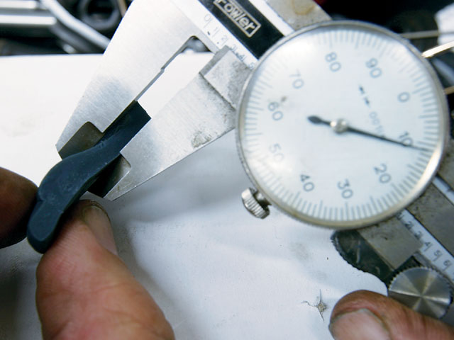
remove the solder and look for indentation ...measure with
dial-caliper ..and this is the valve-to-piston clearance !
No clay mess , no clay spring-back , very much accurate than clay-method
Cut a new piece of solder ...and just repeat for intake side !
Note=>can use solder method to check total deck heights accurately !
----------------------------------------------------------------------
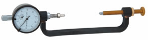
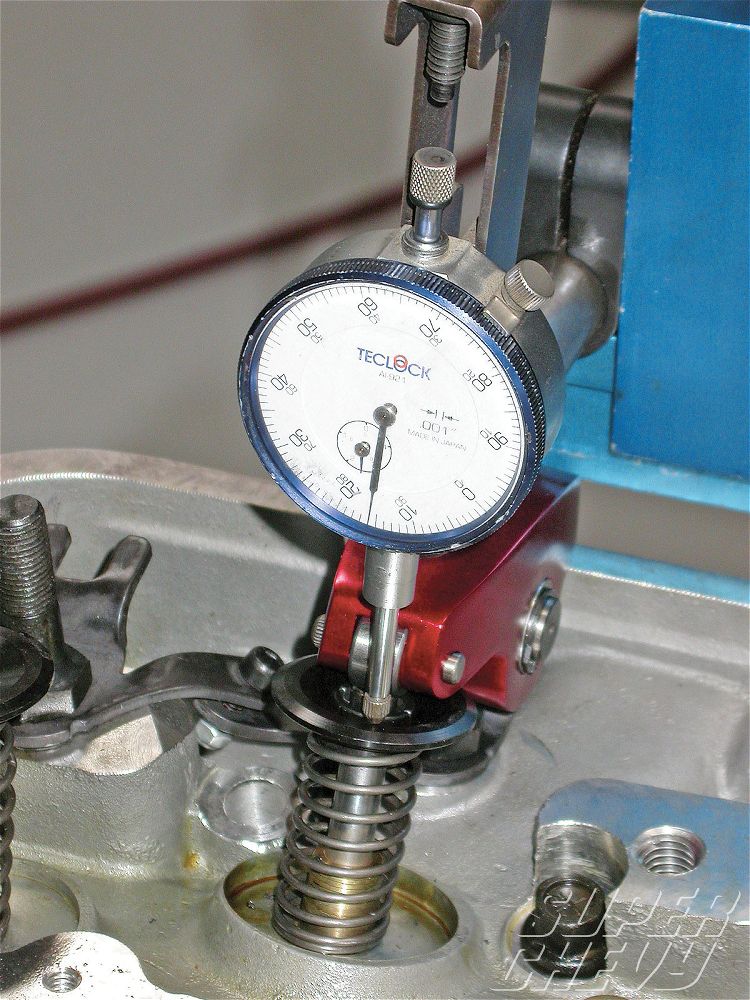
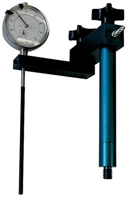
the best method would be to use a 1.000" dial indicator and
magnetic stand ....bolt a 1/8 thick small plate to valve cover
bolt hole then stick the indicator in place on the steel plate .
(sometimes a SBC fuel-pump cover works great)
attach a degree wheel and pointer and find true TDC ,
then turn engine over till 10 degrees BEFORE TDC-Overlap
to measure Exhaust clearance . (8 -to- 12 deg closest points)
at 10 deg BTDC ...place the 1.000" dial indicator's point on
the flat part of the spring retainer , zero the indicator,
and with the set-screw backed out of the adjuster nut, take
a wrench and turn the adjuster nut till you force the valve to
bottom out against the piston's exhaust notch ....read how much
the dial indicator traveled ...thats your Exhaust clearance
back-off Exhaust adjuster nut back to ZERO point on dial indicator
now, repeat the same proceedure on the Intake side ...but this
time turn engine past TDC-Overlap to 10 degrees AFTER TDC
then check Intake clearance .
--------------------------------------------------------------------------
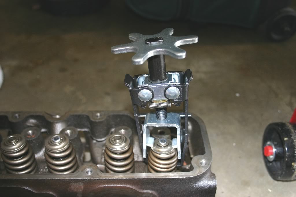
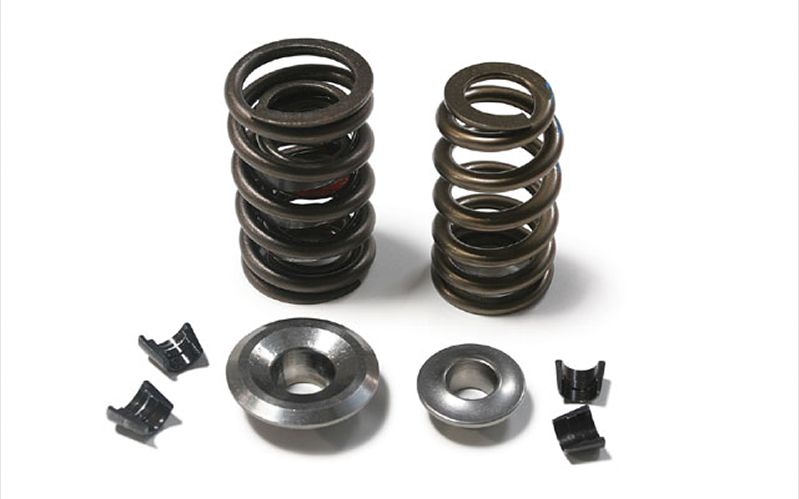
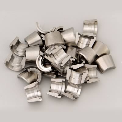
Note : You should always check valve-to-piston clearance with
a fully assembled valvetrain with the real springs in place
and every rocker lashed ...and ONLY turning the engine over in
the direction of rotation (ClockWise).
using light checker type springs will make you flycut pistons
approx. .030" more than necessary ...in other words, what ever
valve-to-piston clearance you check with lite-springs, when the
engine is fully assembled with the real springs, it will have
approx. .030" more clearance !
using lite-checker springs will be a "SAFER" way to check and will
be a good method to use for a beginner engine builder !!!
-------------------------------------------------------------------------
A professional engine builder would use the real springs and watch this
effect upon the cam-twist, Jesel belt distortion, pushrod flex , ETC.
A professional engine builder would check each and every Cylinder's
clearance..and have detailed computer records of things like
1- Piston Intake and Exhaust flycut valve notch depth
2- Piston Valve notch flycut radius , angle + tilt, center-to-bore location
3- Intake and Exhaust valve seat depths on heads, valve margins, etc.
and other things like
4- Total Valve-Notch-Depths
to check the Total Notch Depths ...just place each piston at TDC ,
then place dial indicator zeroed on the top of the valve stem ,
push the valve down till it rests ontop of the piston notch ,
then record this distance !
(need to have springs off , and 2 rubber O-Rings holding up valve
in guides ...when you go to check distance)
As you gain experience and information, you can easily know in advance
what the ballpark valve-to-piston clearance will be with known cam lobes and
rocker ratios , along with cylinder head's valve depth readings , and
piston flycut data .
I try for 0.080-0.120 on the intake and 0.100-0.120 on the exhaust as absolute minimums but am far happier with 0.120 thousands (just under 1/8") or greater on both!
Ill always trade increased clearance to gain reliability for a slight loss in compression,keep in mind that if you get to tight on those clearances you will be locked into that cam timing and dropping it back (RETARDING the cam) for greater high rpm power or (advancing the cam) for more low rpm torque becomes next to impossible in some cases while you tune the engine combo!
http://www.auto-ware.com/software/eap/eap.htm
theres software like I use in the engine shop but its reasonably expensive.............and I still check MANUALLY because I don,t trust software, yeah its usually close, but not exactly correct
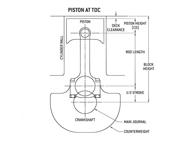
ok first some facts, on piston to valve contact
the valves reach max lift at a time when the pistons not even neat TDC
heres a typical cam timing on a good hydraulic roller cam for a SBC that IVE used frequently
heres a cam timing chart
http://www.crower.com/valve-timing-chart
heres a crank rotation and piston angle chart
http://www.iskycams.com/ART/techinfo/ncrank1.pdf
simple math shows the intake valve reaches max lift near 118 degrees atdc
when the pistons about 3" down the bore
the exhaust reached max lift while the exhaust valve and piston were also reasonably far apart or almost 2.5" down the bore , valves tend to come closest to pistons at about 10- 20 degrees before or after TDC while not nearly at full lift and the duration and LSA of the cam had far more effect than max lift
The ex will be closest between 20 & 5° BTC & the intake 5-20° ATC
Exhaust side
Rotate the engine between 20 & 5 degrees BTC & find the closest point
Intake
Rotate the engine between 5 & 20 degrees ATC & find the closest point
http://www.summitracing.com/parts/pro-66830
Any decent, experienced machine shop can measure your cylinder heads combustion chamber,
and calculate the required clearances after measuring your heads combustion chamber, and then do the correct machine work on your piston domes,
machining the domes for adequate,spark plug,clearance,
this is a very common issue and easily resolved,
most people tend to tell me Im wrong about that use of WD40 spray on the clay, until they try it both ways... yeah the difference is usually minor but five to 10 thousands difference is not rare if the parts are clean and dry versus sprayed with an oil mist
Id be a whole lot happier on a 6000rpm-7000rpm plus engine build, up if my piston to valve clearance, on my engine was .100-.120 inch minimum, clearance even if it required machining the piston valve pocket depth about .060 (don,t forget the valve edge to valve pocket edge clearance)
GET THE CLEARANCES WRONG OR OVER REV THE ENGINE AND BAD THINGS CAN OCCUR, as can ASSUMING THE CLEARANCES ARE CORRECT IF YOU DON,T CHECK
One of the easiest and quickest methods thats a bunch
more accurate than the clay-method , would be to use
Acid-core solder (usually .120" thick )
or
Resin-core solder (usually .090" thick )
READ THIS LINK
http://www.fordmuscle.com/fundamentals/pistontovalve/index.shtml
With the solder-method , you don't actually need a degree wheel
..just the harmonic balancer timing marks and a 6" dial caliper
Turn the engine over till you are coming up to TDC-Overlap
with both the exhaust valve on its way to closing, and
the intake valve beginning to open
Turn the engine till you are about 1/2 inch from TDC ,
then rollout and straighten a piece of acid-core solder about
6 to 8 inches long ....then with headers off , look thru
#1 Cylinder's exhaust port with a penlite...take the solder
and place it thru the spark plug hole , placing solder
across the Exhaust valve piston notch...then hold solder at that
angle while someone slowly turns engine over to TDC-Overlap
and then past TDC until you "feel" you can pull out solder .
as you turn the engine over at TDC the exhaust valve will
touch or squeeze the solder to the valve-to-piston clearance
...as you keep turning engine past TDC-Overlap,
the solder will be released
remove the solder and look for indentation ...measure with
dial-caliper ..and this is the valve-to-piston clearance !
No clay mess , no clay spring-back , very much accurate than clay-method
Cut a new piece of solder ...and just repeat for intake side !
Note=>can use solder method to check total deck heights accurately !
----------------------------------------------------------------------
the best method would be to use a 1.000" dial indicator and
magnetic stand ....bolt a 1/8 thick small plate to valve cover
bolt hole then stick the indicator in place on the steel plate .
(sometimes a SBC fuel-pump cover works great)
attach a degree wheel and pointer and find true TDC ,
then turn engine over till 10 degrees BEFORE TDC-Overlap
to measure Exhaust clearance . (8 -to- 12 deg closest points)
at 10 deg BTDC ...place the 1.000" dial indicator's point on
the flat part of the spring retainer , zero the indicator,
and with the set-screw backed out of the adjuster nut, take
a wrench and turn the adjuster nut till you force the valve to
bottom out against the piston's exhaust notch ....read how much
the dial indicator traveled ...thats your Exhaust clearance
back-off Exhaust adjuster nut back to ZERO point on dial indicator
now, repeat the same proceedure on the Intake side ...but this
time turn engine past TDC-Overlap to 10 degrees AFTER TDC
then check Intake clearance .
--------------------------------------------------------------------------
Note : You should always check valve-to-piston clearance with
a fully assembled valvetrain with the real springs in place
and every rocker lashed ...and ONLY turning the engine over in
the direction of rotation (ClockWise).
using light checker type springs will make you flycut pistons
approx. .030" more than necessary ...in other words, what ever
valve-to-piston clearance you check with lite-springs, when the
engine is fully assembled with the real springs, it will have
approx. .030" more clearance !
using lite-checker springs will be a "SAFER" way to check and will
be a good method to use for a beginner engine builder !!!
-------------------------------------------------------------------------
A professional engine builder would use the real springs and watch this
effect upon the cam-twist, Jesel belt distortion, pushrod flex , ETC.
A professional engine builder would check each and every Cylinder's
clearance..and have detailed computer records of things like
1- Piston Intake and Exhaust flycut valve notch depth
2- Piston Valve notch flycut radius , angle + tilt, center-to-bore location
3- Intake and Exhaust valve seat depths on heads, valve margins, etc.
and other things like
4- Total Valve-Notch-Depths
to check the Total Notch Depths ...just place each piston at TDC ,
then place dial indicator zeroed on the top of the valve stem ,
push the valve down till it rests ontop of the piston notch ,
then record this distance !
(need to have springs off , and 2 rubber O-Rings holding up valve
in guides ...when you go to check distance)
As you gain experience and information, you can easily know in advance
what the ballpark valve-to-piston clearance will be with known cam lobes and
rocker ratios , along with cylinder head's valve depth readings , and
piston flycut data .
I try for 0.080-0.120 on the intake and 0.100-0.120 on the exhaust as absolute minimums but am far happier with 0.120 thousands (just under 1/8") or greater on both!
Ill always trade increased clearance to gain reliability for a slight loss in compression,keep in mind that if you get to tight on those clearances you will be locked into that cam timing and dropping it back (RETARDING the cam) for greater high rpm power or (advancing the cam) for more low rpm torque becomes next to impossible in some cases while you tune the engine combo!
http://www.auto-ware.com/software/eap/eap.htm
theres software like I use in the engine shop but its reasonably expensive.............and I still check MANUALLY because I don,t trust software, yeah its usually close, but not exactly correct
ok first some facts, on piston to valve contact
the valves reach max lift at a time when the pistons not even neat TDC
heres a typical cam timing on a good hydraulic roller cam for a SBC that IVE used frequently
heres a cam timing chart
http://www.crower.com/valve-timing-chart
heres a crank rotation and piston angle chart
http://www.iskycams.com/ART/techinfo/ncrank1.pdf
simple math shows the intake valve reaches max lift near 118 degrees atdc
when the pistons about 3" down the bore
the exhaust reached max lift while the exhaust valve and piston were also reasonably far apart or almost 2.5" down the bore , valves tend to come closest to pistons at about 10- 20 degrees before or after TDC while not nearly at full lift and the duration and LSA of the cam had far more effect than max lift
Attachments
Last edited by a moderator: