Component Selection & Design for 500 HP Fuel System

Still making progress.....yeah!

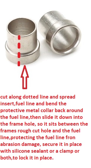
It's obvious to me that that the length you cut the fuel line and the length of the flared lined
are 2 different things. I added 1/16 inch per flare to the length that I measured. See the 2nd
photo for the length I am referring.

FP02_FuelLineToPrReg_00094.jpg

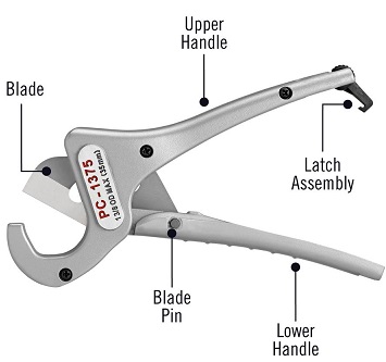
Measure to the widest part of the flare, not to the end of each connection..... then add 1/16 inch
for your cut length. So I measured 2-11/16 inch and I cut it 2-13/16 inch

FP02_MeasuredLength_00097.jpg

When I wired the car I used different colors of shrink tubing to identify different circuits. It really
paid off when tracing these wires back to the fuse panel where maybe 12 wires went thru the firewall.

FP02_SensorWiringRedShrinkTubing_00095.jpg

FP02_PressureRegulatorWiring_00096.jpg
 
Last edited:
as always, I love the clear photos,
its so darn rare, and helpful, too have clear photos documenting any project!
 
Damn you're quick, I'm still editing and adding another photo. But I guess you have been there
many times before.
 
I'm thinking about pulling out the 3/8 inch line that runs inside the frame. So I'm debating about
pulling that steel 3/8 inch line, it's only 3 feet long, not much pressure drop in the 3 feet. If I do
replace it, it would be with the nylon braided hose from Summit Racing. My concerns are where
it run thru the frame on both ends. There will be NO grommet to protect it.

Below is the flexible hose I have and would be using, it does have a Stainless Steel braid between
the nylon braid and the inner liner.
https://www.summitracing.com/parts/sum-240810bp

What would you do, I can never stay on the WO throttle thru the 1/4 mile. I'm only brave enough
to go 100 mph with NO roll bar. My only protection is a Simpson helmet.

DSC00108.JPG


FP01_SummitFuelLineCloseup_00115.jpg

.
 
If your going to work with braided hydraulic line,
https://www.summitracing.com/parts/sum-240810bp
before you cut braided hose slip on a 6" section of 3/4" shrink tube and shrink it in place,
then cut the center of that 6"heat shrink tube as it holds the braided outer layer in place.
https://www.summitracing.com/parts/ear-820188erl/overview/
https://www.homedepot.com/p/RIDGID-...-Stroke-PVC-and-Tubing-Cutter-23493/202056531
23493-40.jpg

but your much better off going to a local hydraulic supply with the correct measurements and let them fabricate,
the line with crimped brass end fittings with protective sleeve ferrel, to your exact specs


https://www.rshughes.com/p/3M-VFP-3...k-Ratio-212-F-Shrink-Temp-59709/051128_59709/

hydraulic_hose.jpg


https://www.summitracing.com/parts/ear-820188erl/media/instructions
 
Last edited:
Have you used this cutter for braided hose? It seems to be for PVC, so just wondering.


There is just no way I can get the hose and FITTINGS thru the hole in the frame. It would take a
much bigger hole of 1 inch and that would be making a sharp bend while traveling thru the hole.

The fitting below would need a 1 inch hole.

FP01_HoseFitting_90°_SUM-220887N.jpg

As it is now I will have to snake the hose thru the frame first and then install the fittings on each end while
I'm under the car. Maybe the photo below will help. It's what I have now with the steel 3/8 inch line. It took
me a 1.5 hours to cut 1/8 inch of the end and then put the AN fitting on the end far enough. Plus I then had
to get the 37° flaring tool on the line. Next I had to tighten everything. But I will be pulling all this out if I
change over to the 1/2 inch braided line.

FP01_-FlareFuelLineInFrame_00101.jpg

The line measurements would have to be exact and I can't measure what it would take to make the S curve
thru the frame holes. Referring to the quote below.

but your much better off going to a local hydraulic supply with the correct measurements and let them fabricate,
the line with crimped brass end fittings with protective sleeve ferrel, to your exact specs

Now why didn't I think of that, I have lots of shrink tubing from my wiring project. I do like that idea!!!
Would I leave it on the line while inserting into the fitting??? I don't see where it would hurt anything.
Referring to the quote below.

before you cut braided hose slip on a 6" section of 3/4" shrink tube and shrink it in place,
then cut the center of that 6"heat shrink tube as it holds the braided outer layer in place.
 
Ive yet to have a leak with the shrink tube over the braided outer hose covering,
but keep in mind the barb fitting must be greased while its forced into the teflon hydraulic hose liner,
and either some type of screw clamp or compression sleeve ,
used to lock the hose on the barbed fitting.
and of course there,s the option of your running the fuel lines outside the frame,
(Maybe inside a section of either 3/4' OR 1"electrical conduit clamped to the inner frame)
and avoiding a great deal of the hassle,\
BTW ITS A WHOLE LOT EASIER TO THREAD BRAIDED FLEX FUEL LINE THROUGH STRAIT SECTIONS,
OF ELECTRICAL CONDUIT ,,
RATHER, THAN TRY TO FORCE THE FUEL LINE THROUGH,
AFTER THEY ARE BENT,
and you can certainly protect that fuel line and place it with pre-custom bent electrical conduit

http://garage.grumpysperformance.co...ers-tube-beading-and-clamps.10128/#post-49413

http://garage.grumpysperformance.co...ubing-fuel-lines-and-flaring.1030/#post-35905
 
Last edited:
but keep in mind the barb fitting must be greased while its forced into the teflon hydraulic hose liner,
and either some type of screw clamp or compression sleeve ,
used to lock the hose on the barbed fitting.

I'm using a different kind of hose, it does not have the PTFE liner, it's a Nitrile Rubber. It does not use
a compression sleeve, therefore it has a different assembly process.

.
 
There are two types of hoses ..... taper and cutter styles. This was confusing to me about which fitting worked where. The link below helps explain the difference.

If you pay attention to the descriptions of the hose ends, you quite often will see those words
Taper or Cutter used.

http://www.onallcylinders.com/2015/12/10/hose-end-how-to-how-to-assemble-cutter-style-hose-ends/

The 3rd paragraph in the article (copied below) helps explain......

There are several different types of quality hose ends available on the market. One is a tapered style;
the other is a cutter style. The cutter style hose end is considered by many in the racing biz to be more
secure than the tapered style. We’ve used both, but the truth is, there are some misconceptions when
it comes to assembling cutter style hose ends. Once those are out of the way, then cutter hose ends
become almost as easy to assemble as the tapered style.
 
I got the old 3/8 inch steel fuel line out. It sure was a mangled mess when I did.

FP02_OldSteelFuelLine_00118.jpg

Had to drill out the front hole so I could get the larger 1/2 line thru the hole (OD=5/8"). Since I
had wires in the frame, I had to make sure they were up out of the way. So I pulled a 5/16 bolt and
made a U shaped tool out of .032 SS wire I had. Below is not it, but that's what it looked like.

FP02_WireTool_00119.jpg

You can see the 5/16 inch bolt hole in the pic below that I pushed the wire tool thru to hold them up out
of the way.

FP02_NewFuelLine_00121.jpg

A pic at the rear where the fuel pump and two filters will be. One pre-filter is a 100 micron and the after filter is a 10 micron.

https://www.summitracing.com/parts/aei-12308
https://www.summitracing.com/parts/aei-12324

FP02_NewFuelLine_00122.jpg
 
well it looks impressive, and its larger in cross sectional area so in theory,
it should provide a much more consistent fuel flow volume.
I think Id try to slide a thin section of tubular bent sheet metal down around the outer fuel feed hose,
so that the potentially sharp edges of that hole drilled in the frame can,t eventually wear through the hose due to vibration.
 
Last edited:
I think Id try to slid a thin section of tubular bent sheet metal down around the outer fuel feed hose,
so that the potentially sharp edges of that hole drilled in the frame can,t eventually wear through the hose due to vibration.

I think I know what you mean. It's like protecting a radiator hose with a short section of radiator
hose split length wise and then wrapped around the good hose located at the point where it rubs.
I searched for a Google photo, but didn't find one to illustrate.

I was planning on using some shrink wrap where it goes thru the frame, but metal would be better
obviously if it will stay in position. If possible I will use both.
 
FuelSleevem.jpg

ideally you'll find something similar to these items and cut one side open ,bend it open,
slide it over the hose and bend it back then slide it down the hose until the larger shoulder won,t let it further progress as the larger side would be up around the outer exposed fuel line while the smaller diameter section would extend down through the frame around the fuel line.with the walls of the smaller diameter,
area,between the fuel line and frame
 
Last edited:
That's a most excellent idea ! THANKS !!!

Do you have any dimension for the inside ID diameter? As I mentioned above I need an hose OD
of 5/8 or slightly larger, like 11/16 inch. I think the 3/4 inch shrink wrap tubing would work nicely
to hold it in place and add a another layer of protection. Time will tell when I try this process.

OH MY GOD GRUMPY ..... Are those your graphics showing the Tube Sleeve ...... I was
starting to believe there was NO hope for your computer skills. It's been sssoooo long since
I've seen a post of yours with such TECHNICAL improvement on your part !!!!!!!!!!!!! :p:p:p


FuelSleevem.jpg
 

Attachments

  • FuelSleeve.jpg
    FuelSleeve.jpg
    53.4 KB · Views: 6
Last edited by a moderator:
I'm long on experience and short on computer manipulation skills but I'm constantly trying to improve....and remember
this tool below got NASA to the moon! and was a computer when I was a 19-21 year old kid in college,in the late 60s
slide.jpg
 
Last edited:
I know what the Holley manual says about mounting their fuel pump, but I'm out of options. I only
have 14 inches to work in the 10 micron filter(left side of photo) and pump with fittings. I need to
mount it on the kick-up, which puts it at 60°.

Can the fuel pump be mounted at 60° ???

FuelSystemPurchaseSummit01_3483.jpg

EBrakeFuelPump_3335.JPG
.
 
yeah, it should work ok mounted that way, I doubt it will have any measurable effect.
Ive seen them mounted laying horizontally in a trunk floor and they worked
 
That's good to hear, because I don't have much of a choice. Well I guess I could start over with
a new car design, but I was hoping to avoid that!!!

The only reason I could come up with was the seal between the pumping cavity and the electric
motor. There is a path along the shaft for fuel to migrate into the motor. But if there is pressure
at the entry of the shaft, then gravity/orientation will have little to do with fuel moving along
that shaft. Holley must have designed into the pump a way to keep fuel out.
 
when you pick a car, a rifle or wife, you always find out there were a few things you failed to realize going into the deal that were unexpected.
or as one of my friends states
"if it has tits,tires or a title, its going too constantly cost you money"
 
Last edited:
Made some progress today with the line from the ......
Fuel Tank >>Shut Off Valve>>Electric Pump>>10 Micron Filter>> Fuel Line Into Frame.

I had to give up the pre-filter (100 Micron). The TBucket is just too short to work everything in. For the
last 10,000 miles all I've had is a NAPA inline filter before the pump without any problems.

I put a 90° line fitting going into the frame to protect the braided fuel line as it goes thru the frame.

FP03_90°BendFuelLineIntoFrame_00127.jpg
FP03_10MicronAeromotiveFilter_00125.jpg

I decided to back into the fuel pump mounting position. It was going to be the last thing to be fixed in
place. As you can see I have it clamped to the frame allowing me to rotate the pump as needed to
align with the other lines.

FP03_FuelPumpInletTubing_00123.jpg
FP03_FuelPumpInletTubing_00124.jpg
 
Back
Top