Grumpy,
After a long pause, we are back working on our 383 project.
I have a couple questions re SBC/383 rotating assembly installation.
I read through many of the links, but could not find an answer.
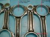
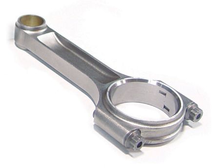
As I understand it SBC 350 5.7 factory rods are offset. If installed with the offset wrong damage will result.
If the rod bearings are installed correctly, doesn't proper orientation of the rod bevel to the crankshaft radiased bevel insure proper offset orientation on installation?
It would seem then that with the rod bevel to the front on odd cylinders and to the rear on even cylinders, exclusive of piston requirements, that any rod could be used in any cylinder and the offset will be correct?
Following on that, with center pin pistons (KB134), with equal size valve reliefs for intake and exhaust, (flat top) no dome or dish and no front indication on the piston, that any piston/rod unit could be used in any cylinder and rod offset and piston orientation would be correct?
Thanks
After a long pause, we are back working on our 383 project.
I have a couple questions re SBC/383 rotating assembly installation.
I read through many of the links, but could not find an answer.
As I understand it SBC 350 5.7 factory rods are offset. If installed with the offset wrong damage will result.
If the rod bearings are installed correctly, doesn't proper orientation of the rod bevel to the crankshaft radiased bevel insure proper offset orientation on installation?
It would seem then that with the rod bevel to the front on odd cylinders and to the rear on even cylinders, exclusive of piston requirements, that any rod could be used in any cylinder and the offset will be correct?
Following on that, with center pin pistons (KB134), with equal size valve reliefs for intake and exhaust, (flat top) no dome or dish and no front indication on the piston, that any piston/rod unit could be used in any cylinder and rod offset and piston orientation would be correct?
Thanks