I build mostly BBC engines, but most of this info also applies to SBC connecting rod selection,
I was asked if stock rods were ok or should they swap to better ARP bolts or BUY the BETTER RODS WITH THE UPGRADED BOLTS,
the first thing Id point out is that, in most cases, when I diagnose engine failures , I see that its usually related to rod bolt stretch or valve train control issues or failures to check clearances, or occasionally failure to provide cooling or lubrication that are the major factors that cause problems, but by far, failure to check clearances, valve train stability issues at higher rpms and rod bolt stretch, and detonation issues are more common.
no connecting rod made can successfully compress bent valves or loose chunks of detonation damaged piston, without damage occurring
http://www.wiseco.com/Calculators.aspx
http://garage.grumpysperformance.co...-about-your-potential-dream-bbc-combos.14607/
failure to verify clearances, verify valve train geometry , provide lubrication, and maintain cooling , stay out of DETONATION,or use of inferior components or exceeding your engines valve train control limitations, or red line on rotating assembly design strength can get darn expensive
read these links
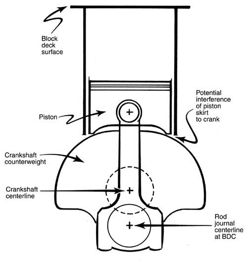
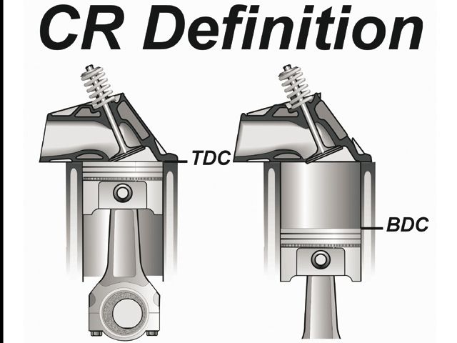
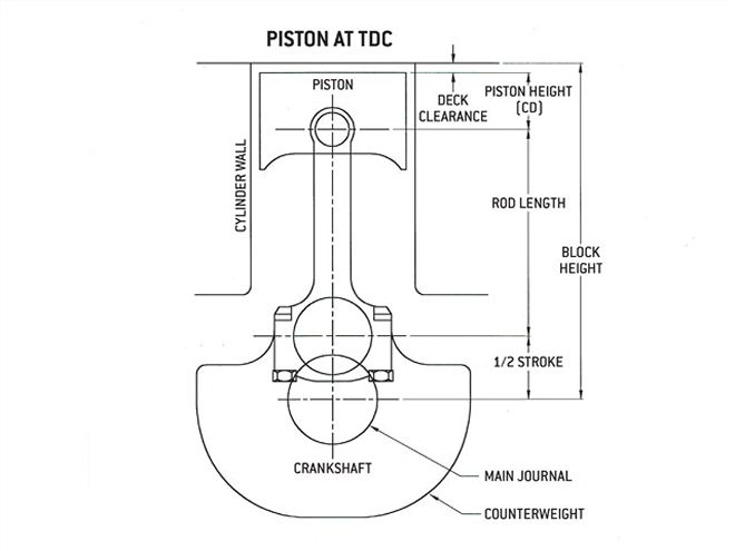
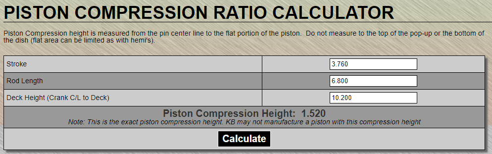
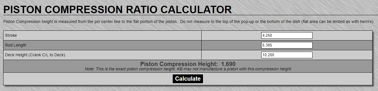
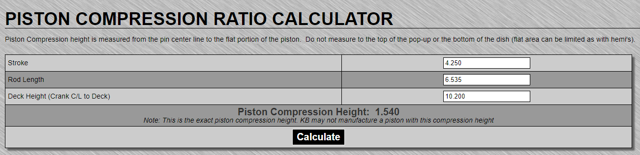
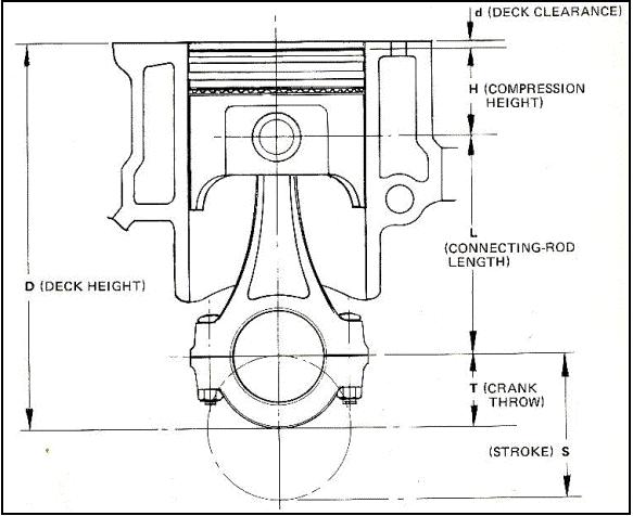
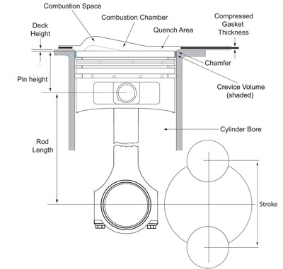
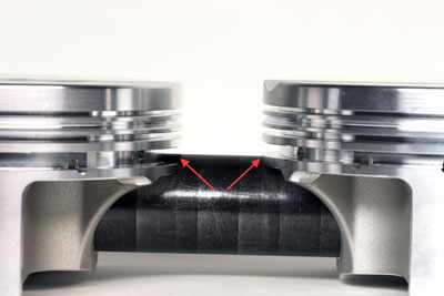
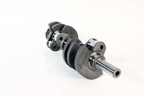
notice how the longer crank stroke effects the piston stroke distance in the bore, both at the lower and upper end of the cylinder
http://arp-bolts.com/pages/technical_failures.shtml
http://www.hotrod.com/techarticles/stee ... index.html
http://garage.grumpysperformance.co...calculate-the-bore-stroke-displacement.14906/
link too bore vs stroke info on hundreds of engines
http://users.erols.com/srweiss/tablersn.htm
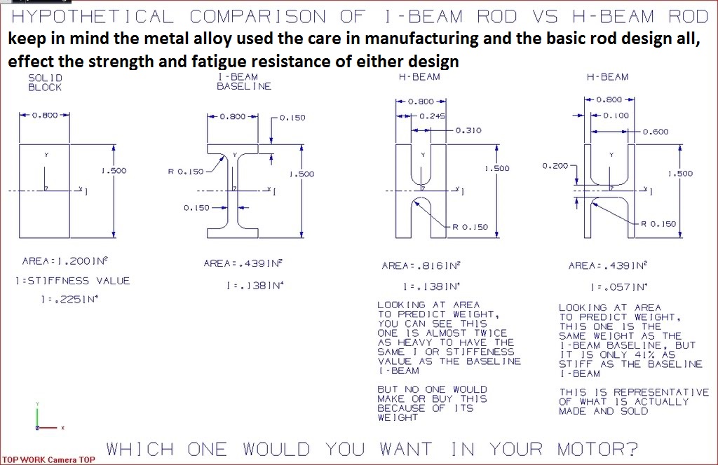
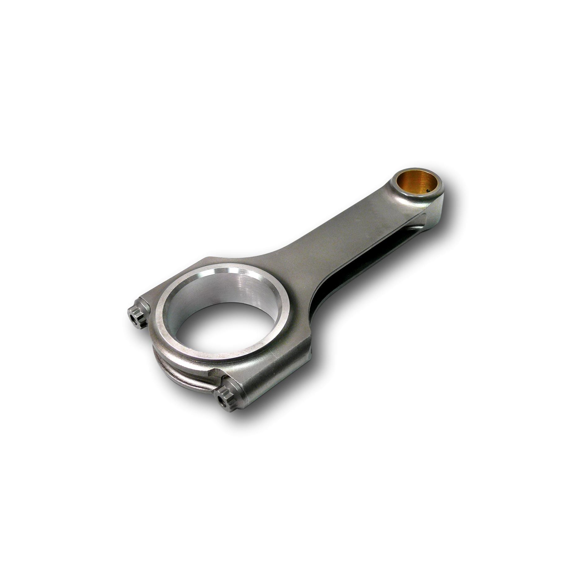
the 7/16" ARP connecting rod bolts are about 18% larger in cross sectional area than the 3/8" bolts and the better L19 or ARP 2000 bolts are a MINIMUM of 150% stronger than stock bolts even in the smaller 3/8" size,, the larger 7/16" is at least 200% stronger than the stock bolts in the rods., now rods can fail from high rpms and stress in other areas but its the rod bolts that fail in many cases, and in no case would I advise the use of stock 3/8" bolt connecting rods with lots of mileage on them be reused. the (H) design rods can be made slightly lighter in total weight than a similar (I) beam rod, in the common 4340 steel forgings ,but tends to cost slightly more,(notice I DIDN'T SAY I BEAM RODS are STRONGER, but STRONGER FOR A GIVEN WEIGHT) the weak point is usually the connecting rod bolts not the rod forging itself, always go with the 7/16" ARP bolts and the BOLT upgrade is advisable to L19 or better bolts once you start expecting to exceed 4000 feet per minute in piston speed, and its almost mandatory over 600hp and 4500 fpm (FEET PER MINUTE)in piston speed.
strength, obviously it depends on materials, design, care in manufacturing and which connecting rods are being compared properly prepared LS7 or L88 big block rods are a whole lot stronger than the stock 3/8" rod bolts big block rods, but many of the better aftermarket rods are significantly stronger that even the l88 rods
I beam rods typically have a balance pad and thats a good feature, typical H beam rods are SUPPOSED TO BE nearly identical in weight, as they are usually machined not castings (obviously they too occasionally need to be balanced)
theres not a thing wrong with either the (H) or (I) designs if the quality is there in the design and manufacturing.
for most high performance cars,the choice should probably be based on which design has better clearance too the cam lobes and block rails and the use of 7/16" arp bolts, and what kind of package deal you can get on an INTERNALLY BALANCED CRANK, DESIGNED FOR THE RODS if your looking to build the better assembly.
If your build any BBC engine as a general rule, you can expect to see about 1-to-1.3 hp and 1.2-to-1.4 ft lbs of torque per cubic inch of displacement at the flywheel, from a properly designed engine, using higher quality components,
yes you can improve both figures but as power goes up so does component cost.
so basically there's a noticeable boost in power if you build the larger displacement engines, especially if you keep the compression ratio. up or above 9.5:1, max power will require race octane fuel and compression ratios above 12.5:1, and cams with enough lift and duration to make low speed driving in traffic miserable, and these engines will NOT be useful designs for street performance use.
look most stock chevy connecting rods are rated at no more than 6000rpm and 450-500hp
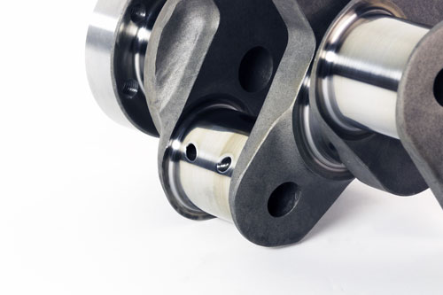
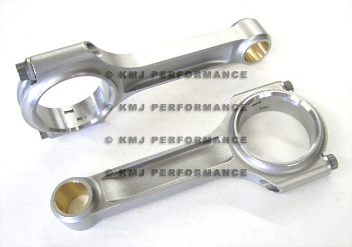
one factor to keep in mind is that rods typically have a side that rides against its matched companion and a side thats BEVELED for clearance on the crank journals radias EXAMPLE
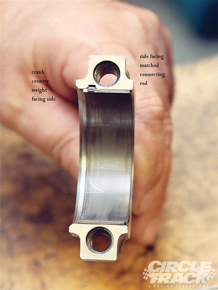
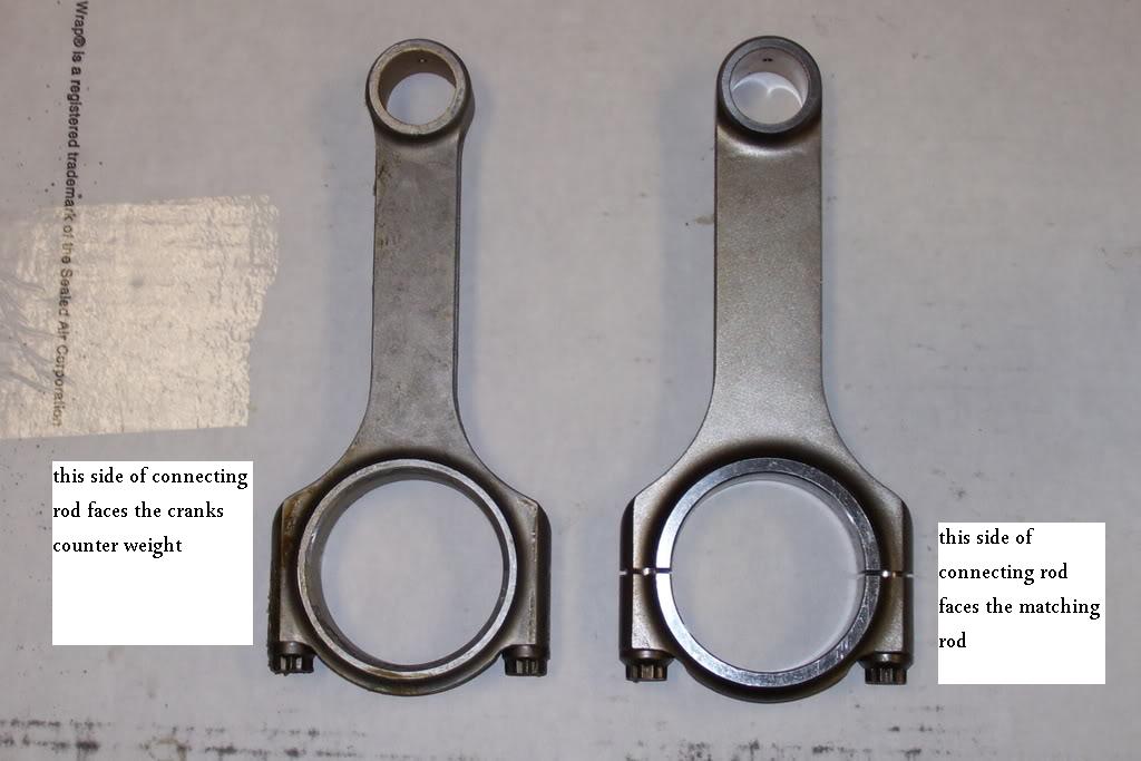
notice how one side of the bearing holding section has a radias (left) but the opposite sides flush (right)
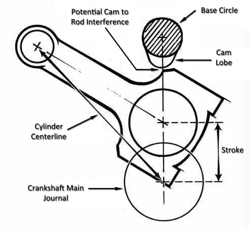
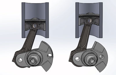
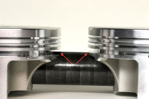
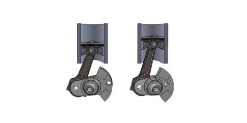
if you wonder why I suggest using SCAT (H) beam style cap screw connecting rods vs stock or most (I) beam designs this picture should show the increased cam to connecting rod clearance
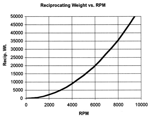
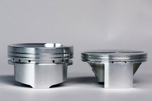
the best solution from a performance perspective is to do the required calculations to select the longest length connecting rod and the lowest weight piston,
of a decent design that will reduce the reciprocating mass significantly more.
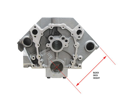
the tall deck has a 10.2" deck height, a good dual plane aluminum high rise intake manifold will tend to provide the best compromise if you use a low compression and mild cam duration,
while it might seem like a waste of time, now, reading the links and sub-links will provide a good base to work from, later and save you a great deal of wasted time and money
you have a choice, you can slap the components you own together, now and live with what you have built regardless of the results , or you can put some real thought into making the result perform and carefully select parts and significantly boost power... yes that routes more expensive up front, but in the long term it tends to get better results and cost LESS.
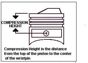
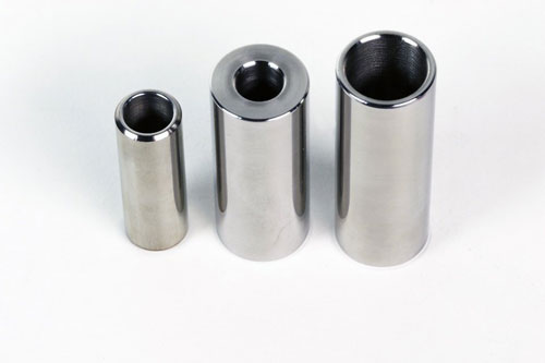
common BB CHEVY piston compression heights are
1.270"
1.395"
1.520"
1.645"
1.765"
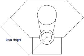
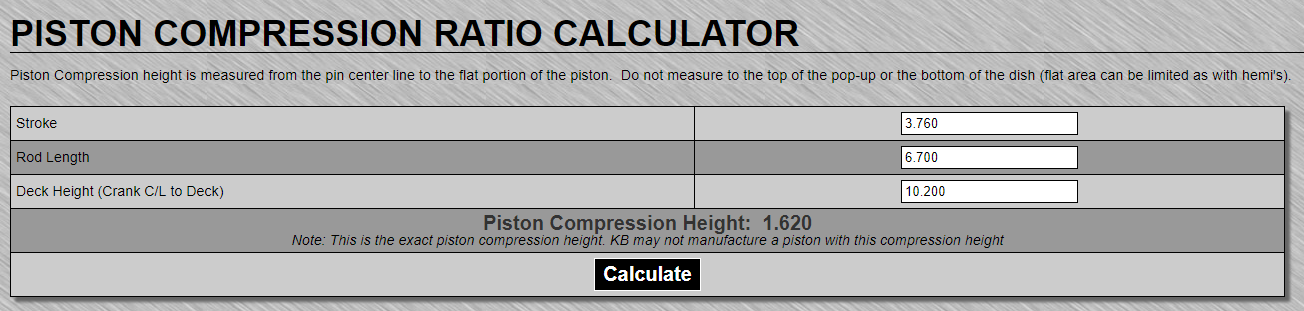
remember the blocks deck height, minus the piston pin height minus 1/2 the crank stroke will equal the required connecting rod length
OR
the blocks deck height, minus the connecting rod length, minus 1/2 the crank stroke. will equal the required piston pin height
if you wonder why I suggest using SCAT (H) beam style cap screw connecting rods vs stock or most (I) beam designs this picture should show the increased cam to connecting rod clearance
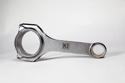
After market performance ,big block connecting rods come in several common lengths
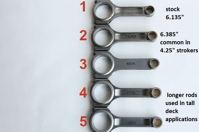
6.7-6.8"
https://www.summitracing.com/parts/esp-67003dl19/overview/make/chevrolet
https://www.summitracing.com/parts/cpi-u16230/overview/make/chevrolet
https://www.summitracing.com/parts/sca-6670022a/overview/make/chevrolet
https://www.summitracing.com/parts/sca-6680022a/overview/make/chevrolet
https://www.summitracing.com/parts/sca-6680022/overview/make/chevrolet
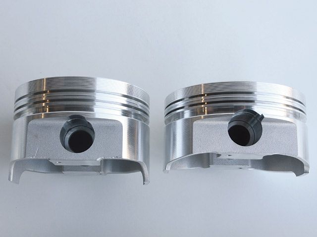
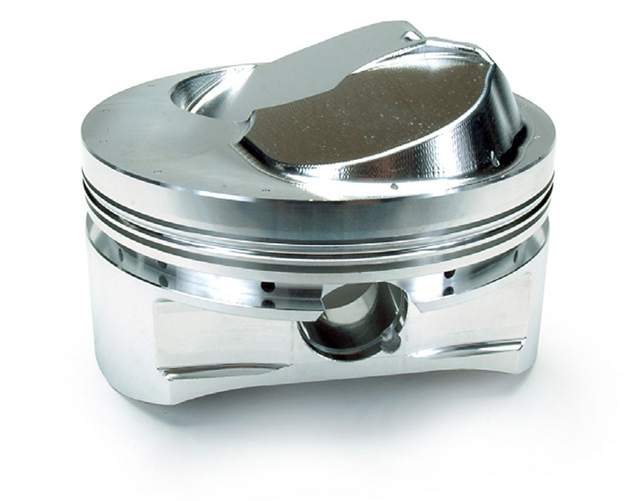
notice the pin height in the pistons pictured above allow a longer or shorter connecting rod length
heres a selection of commonly available big block chevy connecting rod lengths
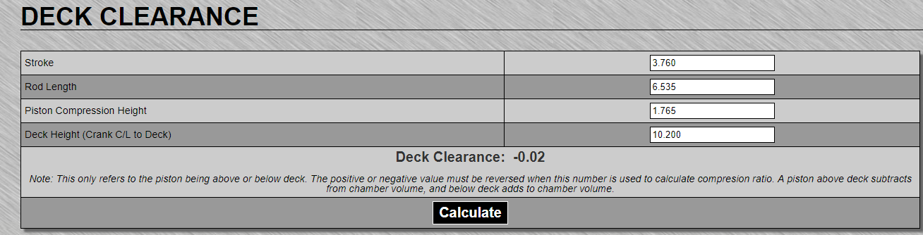
https://www.uempistons.com/index.php?main_page=calculators&type=deck
https://www.uempistons.com/index.ph...n_comp&zenid=a0b4d1c0899b781e5a1cffb2fe0afe21
your going to want the longer length and 150%-200% stronger aftermarket connecting rods with the much stronger 7/16" ARP rod bolts if your building a tall deck BBC engine,
so if your trying to build the best combo, you should select the longest and strongest connecting rods that allows you to select an off the shelf compression height piston to save money,
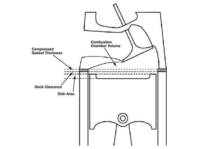
keep in mind head gaskets come in head gaskets come in .010 steps from about .020-to-about .80 and blocks generally measure 10.223 if that O.E.M. block has not previously machined, try too get the quench in the .040-.044 range,
you can get the piston thats compression height is .010-.015, .020 , .025, below or above the deck height, and with a matched head gasket get the quench correct after measuring the deck height, and compression height.
I recently helped one of the local guys assemble a 496 BBC 4.25" stroke
engine using 6.385: SCAT rods with 12.7:1 pistons thats being built
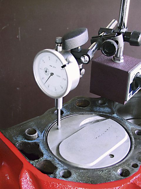
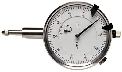
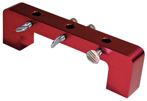
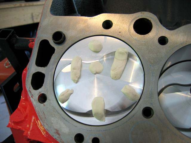
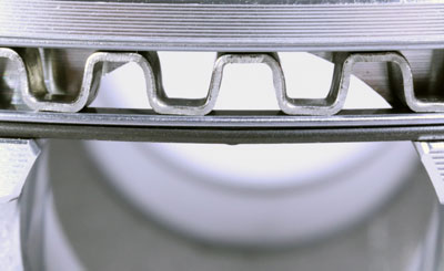
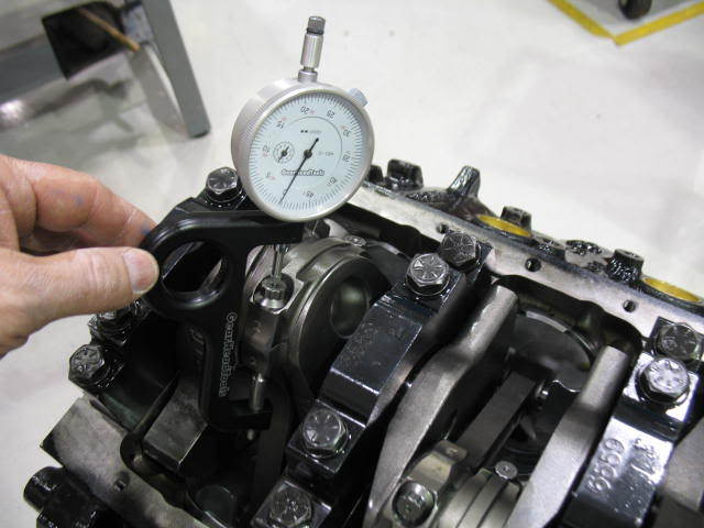
I watched him start to install the first piston with the dome facing the lifter gallery, or upper side of the cylinder... I waited until he had started to install the connecting rod cap on that first rod and asked him to rotate the crank to TDC I handed him a bridge and a dial indicator
https://www.uempistons.com/index.php?main_page=calculators&type=deck
https://www.uempistons.com/index.ph...n_comp&zenid=a0b4d1c0899b781e5a1cffb2fe0afe21
and asked him to verify the deck height.....honestly I had a real hard time not laughing.....I think most of us realize that we all made similar mistakes.... no harm done (YET).
after a few seconds, I suggested he check the spark plug clearance with the head just laid on the block with an old head gasket...yeah, he caught the mistake then!
https://mobiloil.com/en/article/car...w-to-assemble-an-engine-part-2-the-bottom-end
http://garage.grumpysperformance.co...ed-holes-in-bearings-shells.10750/#post-53298
https://mobiloil.com/en/article/car...w-to-assemble-an-engine-part-2-the-bottom-end
http://garage.grumpysperformance.co...d-side-clearance-dont-assume.4690/#post-12702
http://garage.grumpysperformance.co...nk-durring-short-blk-assembly.852/#post-39417
http://www.hotrod.com/articles/0901phr-less-expensive-big-block-chevy-engine/
http://garage.grumpysperformance.com/index.php?threads/measuring-rod-and-pin-heights.3760/#post-9968
http://garage.grumpysperformance.com/index.php?threads/deck-height-problems.3048/#post-8048
http://garage.grumpysperformance.com/index.php?threads/quench-squish.726/#post-1023
http://garage.grumpysperformance.com/index.php?threads/sealants-and-threads.805/#post-71928
http://garage.grumpysperformance.com/index.php?threads/head-gasket-related.1859/#post-50617
https://www.uempistons.com/index.ph...e=deck&zenid=823ce2c9e2ffa691864d832c10107df0
https://www.uempistons.com/index.php?main_page=calculators&zenid=823ce2c9e2ffa691864d832c10107df0
heres a selection of commonly available big block chevy connecting rod lengths
now I may be in the small minority here, but I have always given away 3/8" bolt sbc or bbc rods rather than use them and purchased the 7/16" versions or aftermarket 7/16" cap screw rods, WITH the L19 bolt upgrade,the 7/16" rods ARE significantly stronger. rod bolts are critical, high stress items and one of the areas most likely to cause problems at high rpms and loads.
cross sectional area of a 3/8" bolt is approx .11 sq inches, a 7/16" bolt is approx .15 sq inches BTW when you go to buy a ring compressor....this type works far better than the others
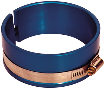
http://store.summitracing.com/partdetail.asp?autofilter=1&part=PRO-66766&N=700+115&autoview=sku
http://garage.grumpysperformance.co...g-and-installing-connecting-rods-pistons.247/
Proform 66766 $31
common sbc pin height info
Specs
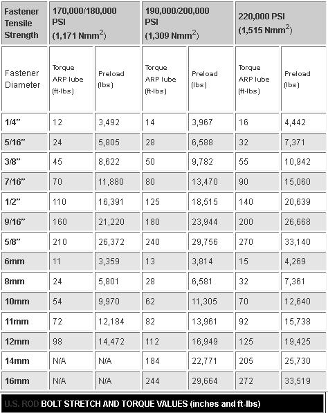
use those good L19 bolts and assuming you sellected the good L19 bolts that test at 220,000 psi, for each the differance is 24.2 thousand lbs vs 33 thousand lbs or a 36% increase in strength, but the stock rod bolts are 160,000 psi so your really swapping from about 17.6 thousand to 33 thousand in strength or an 88% stronger rod bolt
http://arp-bolts.com/pages/technical_torque_us.shtml
http://arp-bolts.com/pages/technical_installation.shtml
http://issuu.com/arpbolts/docs/catalog2 ... ipBtn=true
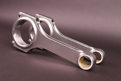
reasonable quality connecting rods are CHEAP
http://www.cnc-motorsports.com/product.asp?ProdID=3150
http://www.cnc-motorsports.com/product.asp?ProdID=8817
keep in mind if a rod comes loose at high rpms you'll be LUCKY to save the intake, heads, blocks and cam are frequently damaged, spending an extra $90 for the better rod bolts is a total no brainer, in my opinion, if spending an extra $400-500 on rods and $90 on better bolts prevents rod failures, thats a minor consideration, when you may be spending $5500-$12,000 plus on an engine build.
you might also want to be aware that over revving and floating the valves, and using a poorly designed oil system is a major potential source of engine failures
I see rods and rod bolt failures blamed frequently when engines self destruct at high rpms, but its NOT always what it at first might appear to be....are there any detailed pictures of the rods or rod bolts that failed??? in many cases the source of the problem can be seen with a careful detailed exam, if you don,t know the SOURCE of the problem your doomed to repeat the sequence... and keep in mind a good deal of what might appear to be rod/rod bolt failures, are ACTUALLY the result of over revving the valve train,and loss of valve train control, OR detonation, theres no way to compress a bent valve or broken piston ring land without potentially damaging the rods
well worth reading
http://www.rehermorrison.com/techtalk/63.htm
http://arp-bolts.com/pages/technical_failures.shtml
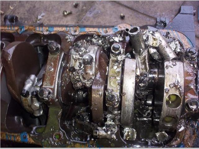
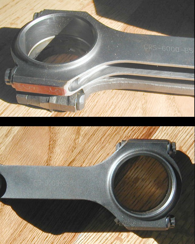
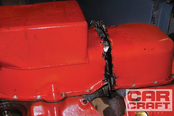
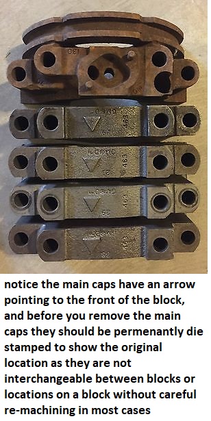
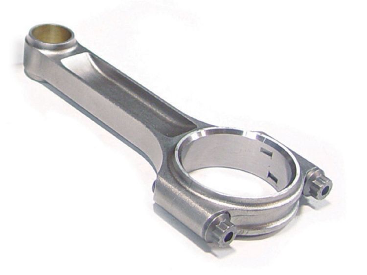
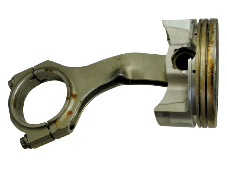
IM OFTEN ASKED WHY I DON,T REBUILD CHEVY CONNECTING RODS, WELL MAYBE A PICTURE WILL HELP,
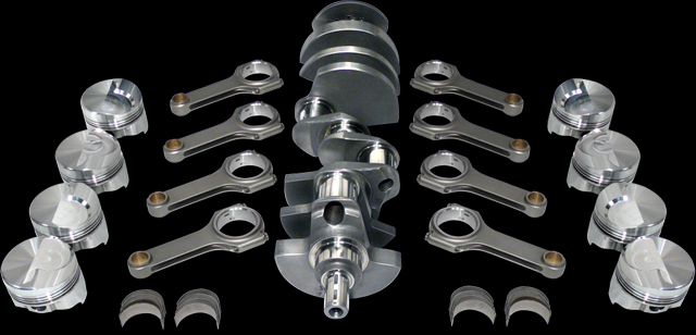
a good set of SCAT FORGED 4340 forged connecting rods costs less than $400 and they are 150%-200% stronger than MOST OEM chevy SBC rods
it will cost you almost that much to replace the bolts with ARP wave lock bolts, balance and polish and resize stock rods and you have far weaker rods when your done

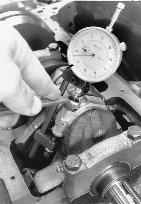
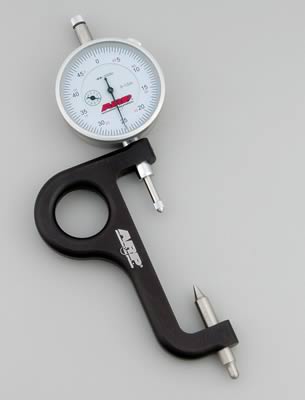
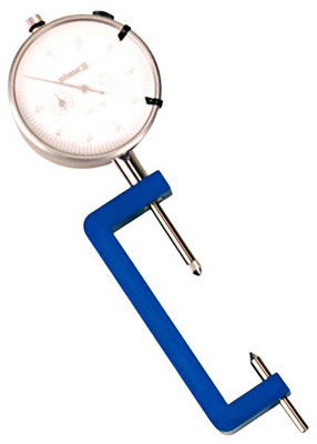
Do not assume all the rod bolts will all take the same torque to get to the specified listed stretch
SUMMIT SELLS ROD BOLT STRETCH GAUGES
http://www.summitracing.com/parts/ARP-100-9942/
I was asked if stock rods were ok or should they swap to better ARP bolts or BUY the BETTER RODS WITH THE UPGRADED BOLTS,
the first thing Id point out is that, in most cases, when I diagnose engine failures , I see that its usually related to rod bolt stretch or valve train control issues or failures to check clearances, or occasionally failure to provide cooling or lubrication that are the major factors that cause problems, but by far, failure to check clearances, valve train stability issues at higher rpms and rod bolt stretch, and detonation issues are more common.
no connecting rod made can successfully compress bent valves or loose chunks of detonation damaged piston, without damage occurring
some basic bbc math, to get you thinking about your potential dream bbc combos.
I recently had a discussion with one of the local guys concerning what heads and rotating assembly he should buy now that he recently purchased a tall deck (10.2") big block chevy block. he has a perfectly good 427 forged crank (3.76" stroke) but hes seriously thinking of buying a (4.25" stroke)...
garage.grumpysperformance.com
http://www.wiseco.com/Calculators.aspx
http://garage.grumpysperformance.co...-about-your-potential-dream-bbc-combos.14607/
Damper Size for 327
Hi guys I just sent my short block out to get redone. new rods ( scat), pistons .060 over racetec. small journal 327. ARP everywhere. I had a 8in performance damper and the guy doing the work ( one of the best in the area) said the 6in is what he recommends. He will of course rebalance the...
garage.grumpysperformance.com
failure to verify clearances, verify valve train geometry , provide lubrication, and maintain cooling , stay out of DETONATION,or use of inferior components or exceeding your engines valve train control limitations, or red line on rotating assembly design strength can get darn expensive
read these links
notice how the longer crank stroke effects the piston stroke distance in the bore, both at the lower and upper end of the cylinder
http://arp-bolts.com/pages/technical_failures.shtml
http://www.hotrod.com/techarticles/stee ... index.html
http://garage.grumpysperformance.co...calculate-the-bore-stroke-displacement.14906/
link too bore vs stroke info on hundreds of engines
http://users.erols.com/srweiss/tablersn.htm
the 7/16" ARP connecting rod bolts are about 18% larger in cross sectional area than the 3/8" bolts and the better L19 or ARP 2000 bolts are a MINIMUM of 150% stronger than stock bolts even in the smaller 3/8" size,, the larger 7/16" is at least 200% stronger than the stock bolts in the rods., now rods can fail from high rpms and stress in other areas but its the rod bolts that fail in many cases, and in no case would I advise the use of stock 3/8" bolt connecting rods with lots of mileage on them be reused. the (H) design rods can be made slightly lighter in total weight than a similar (I) beam rod, in the common 4340 steel forgings ,but tends to cost slightly more,(notice I DIDN'T SAY I BEAM RODS are STRONGER, but STRONGER FOR A GIVEN WEIGHT) the weak point is usually the connecting rod bolts not the rod forging itself, always go with the 7/16" ARP bolts and the BOLT upgrade is advisable to L19 or better bolts once you start expecting to exceed 4000 feet per minute in piston speed, and its almost mandatory over 600hp and 4500 fpm (FEET PER MINUTE)in piston speed.
strength, obviously it depends on materials, design, care in manufacturing and which connecting rods are being compared properly prepared LS7 or L88 big block rods are a whole lot stronger than the stock 3/8" rod bolts big block rods, but many of the better aftermarket rods are significantly stronger that even the l88 rods
I beam rods typically have a balance pad and thats a good feature, typical H beam rods are SUPPOSED TO BE nearly identical in weight, as they are usually machined not castings (obviously they too occasionally need to be balanced)
theres not a thing wrong with either the (H) or (I) designs if the quality is there in the design and manufacturing.
for most high performance cars,the choice should probably be based on which design has better clearance too the cam lobes and block rails and the use of 7/16" arp bolts, and what kind of package deal you can get on an INTERNALLY BALANCED CRANK, DESIGNED FOR THE RODS if your looking to build the better assembly.
If your build any BBC engine as a general rule, you can expect to see about 1-to-1.3 hp and 1.2-to-1.4 ft lbs of torque per cubic inch of displacement at the flywheel, from a properly designed engine, using higher quality components,
yes you can improve both figures but as power goes up so does component cost.
so basically there's a noticeable boost in power if you build the larger displacement engines, especially if you keep the compression ratio. up or above 9.5:1, max power will require race octane fuel and compression ratios above 12.5:1, and cams with enough lift and duration to make low speed driving in traffic miserable, and these engines will NOT be useful designs for street performance use.
look most stock chevy connecting rods are rated at no more than 6000rpm and 450-500hp
one factor to keep in mind is that rods typically have a side that rides against its matched companion and a side thats BEVELED for clearance on the crank journals radias EXAMPLE
notice how one side of the bearing holding section has a radias (left) but the opposite sides flush (right)
if you wonder why I suggest using SCAT (H) beam style cap screw connecting rods vs stock or most (I) beam designs this picture should show the increased cam to connecting rod clearance
the best solution from a performance perspective is to do the required calculations to select the longest length connecting rod and the lowest weight piston,
of a decent design that will reduce the reciprocating mass significantly more.
the tall deck has a 10.2" deck height, a good dual plane aluminum high rise intake manifold will tend to provide the best compromise if you use a low compression and mild cam duration,
while it might seem like a waste of time, now, reading the links and sub-links will provide a good base to work from, later and save you a great deal of wasted time and money
you have a choice, you can slap the components you own together, now and live with what you have built regardless of the results , or you can put some real thought into making the result perform and carefully select parts and significantly boost power... yes that routes more expensive up front, but in the long term it tends to get better results and cost LESS.
common BB CHEVY piston compression heights are
1.270"
1.395"
1.520"
1.645"
1.765"
remember the blocks deck height, minus the piston pin height minus 1/2 the crank stroke will equal the required connecting rod length
OR
the blocks deck height, minus the connecting rod length, minus 1/2 the crank stroke. will equal the required piston pin height
if you wonder why I suggest using SCAT (H) beam style cap screw connecting rods vs stock or most (I) beam designs this picture should show the increased cam to connecting rod clearance
After market performance ,big block connecting rods come in several common lengths
6.7-6.8"
https://www.summitracing.com/parts/esp-67003dl19/overview/make/chevrolet
https://www.summitracing.com/parts/cpi-u16230/overview/make/chevrolet
https://www.summitracing.com/parts/sca-6670022a/overview/make/chevrolet
https://www.summitracing.com/parts/sca-6680022a/overview/make/chevrolet
https://www.summitracing.com/parts/sca-6680022/overview/make/chevrolet
notice the pin height in the pistons pictured above allow a longer or shorter connecting rod length
heres a selection of commonly available big block chevy connecting rod lengths
https://www.uempistons.com/index.php?main_page=calculators&type=deck
https://www.uempistons.com/index.ph...n_comp&zenid=a0b4d1c0899b781e5a1cffb2fe0afe21
your going to want the longer length and 150%-200% stronger aftermarket connecting rods with the much stronger 7/16" ARP rod bolts if your building a tall deck BBC engine,
so if your trying to build the best combo, you should select the longest and strongest connecting rods that allows you to select an off the shelf compression height piston to save money,
keep in mind head gaskets come in head gaskets come in .010 steps from about .020-to-about .80 and blocks generally measure 10.223 if that O.E.M. block has not previously machined, try too get the quench in the .040-.044 range,
you can get the piston thats compression height is .010-.015, .020 , .025, below or above the deck height, and with a matched head gasket get the quench correct after measuring the deck height, and compression height.
I recently helped one of the local guys assemble a 496 BBC 4.25" stroke
engine using 6.385: SCAT rods with 12.7:1 pistons thats being built
I watched him start to install the first piston with the dome facing the lifter gallery, or upper side of the cylinder... I waited until he had started to install the connecting rod cap on that first rod and asked him to rotate the crank to TDC I handed him a bridge and a dial indicator
https://www.uempistons.com/index.php?main_page=calculators&type=deck
https://www.uempistons.com/index.ph...n_comp&zenid=a0b4d1c0899b781e5a1cffb2fe0afe21
and asked him to verify the deck height.....honestly I had a real hard time not laughing.....I think most of us realize that we all made similar mistakes.... no harm done (YET).
after a few seconds, I suggested he check the spark plug clearance with the head just laid on the block with an old head gasket...yeah, he caught the mistake then!
https://mobiloil.com/en/article/car...w-to-assemble-an-engine-part-2-the-bottom-end
http://garage.grumpysperformance.co...ed-holes-in-bearings-shells.10750/#post-53298
https://mobiloil.com/en/article/car...w-to-assemble-an-engine-part-2-the-bottom-end
http://garage.grumpysperformance.co...d-side-clearance-dont-assume.4690/#post-12702
http://garage.grumpysperformance.co...nk-durring-short-blk-assembly.852/#post-39417
http://www.hotrod.com/articles/0901phr-less-expensive-big-block-chevy-engine/
http://garage.grumpysperformance.com/index.php?threads/measuring-rod-and-pin-heights.3760/#post-9968
http://garage.grumpysperformance.com/index.php?threads/deck-height-problems.3048/#post-8048
http://garage.grumpysperformance.com/index.php?threads/quench-squish.726/#post-1023
http://garage.grumpysperformance.com/index.php?threads/sealants-and-threads.805/#post-71928
http://garage.grumpysperformance.com/index.php?threads/head-gasket-related.1859/#post-50617
https://www.uempistons.com/index.ph...e=deck&zenid=823ce2c9e2ffa691864d832c10107df0
https://www.uempistons.com/index.php?main_page=calculators&zenid=823ce2c9e2ffa691864d832c10107df0
heres a selection of commonly available big block chevy connecting rod lengths
now I may be in the small minority here, but I have always given away 3/8" bolt sbc or bbc rods rather than use them and purchased the 7/16" versions or aftermarket 7/16" cap screw rods, WITH the L19 bolt upgrade,the 7/16" rods ARE significantly stronger. rod bolts are critical, high stress items and one of the areas most likely to cause problems at high rpms and loads.
cross sectional area of a 3/8" bolt is approx .11 sq inches, a 7/16" bolt is approx .15 sq inches BTW when you go to buy a ring compressor....this type works far better than the others
http://store.summitracing.com/partdetail.asp?autofilter=1&part=PRO-66766&N=700+115&autoview=sku
http://garage.grumpysperformance.co...g-and-installing-connecting-rods-pistons.247/
Proform 66766 $31
common sbc pin height info
Specs
- Comp Height 5.565" Rod - 1.561
- Comp Height 5.7" Rod - 1.433
- Comp Height 6.0" Rod - 1.13
- Pin Diameter - 0.9272
use those good L19 bolts and assuming you sellected the good L19 bolts that test at 220,000 psi, for each the differance is 24.2 thousand lbs vs 33 thousand lbs or a 36% increase in strength, but the stock rod bolts are 160,000 psi so your really swapping from about 17.6 thousand to 33 thousand in strength or an 88% stronger rod bolt
http://arp-bolts.com/pages/technical_torque_us.shtml
http://arp-bolts.com/pages/technical_installation.shtml
redline
youll generally find that 4000 FPM (FEET PER MINUTE)of piston speed with stock parts or 4500fpm with VERY good quality forged parts is the reasonable limit on the lower end ROTATING ASSEMBLY stress, if you don,t think selecting high quality components and correctly assembling them is...
garage.grumpysperformance.com
http://issuu.com/arpbolts/docs/catalog2 ... ipBtn=true
reasonable quality connecting rods are CHEAP
http://www.cnc-motorsports.com/product.asp?ProdID=3150
http://www.cnc-motorsports.com/product.asp?ProdID=8817
keep in mind if a rod comes loose at high rpms you'll be LUCKY to save the intake, heads, blocks and cam are frequently damaged, spending an extra $90 for the better rod bolts is a total no brainer, in my opinion, if spending an extra $400-500 on rods and $90 on better bolts prevents rod failures, thats a minor consideration, when you may be spending $5500-$12,000 plus on an engine build.
you might also want to be aware that over revving and floating the valves, and using a poorly designed oil system is a major potential source of engine failures
I see rods and rod bolt failures blamed frequently when engines self destruct at high rpms, but its NOT always what it at first might appear to be....are there any detailed pictures of the rods or rod bolts that failed??? in many cases the source of the problem can be seen with a careful detailed exam, if you don,t know the SOURCE of the problem your doomed to repeat the sequence... and keep in mind a good deal of what might appear to be rod/rod bolt failures, are ACTUALLY the result of over revving the valve train,and loss of valve train control, OR detonation, theres no way to compress a bent valve or broken piston ring land without potentially damaging the rods
well worth reading
http://www.rehermorrison.com/techtalk/63.htm
http://arp-bolts.com/pages/technical_failures.shtml
IM OFTEN ASKED WHY I DON,T REBUILD CHEVY CONNECTING RODS, WELL MAYBE A PICTURE WILL HELP,
a good set of SCAT FORGED 4340 forged connecting rods costs less than $400 and they are 150%-200% stronger than MOST OEM chevy SBC rods
it will cost you almost that much to replace the bolts with ARP wave lock bolts, balance and polish and resize stock rods and you have far weaker rods when your done
Do not assume all the rod bolts will all take the same torque to get to the specified listed stretch
SUMMIT SELLS ROD BOLT STRETCH GAUGES
http://www.summitracing.com/parts/ARP-100-9942/
Last edited by a moderator:

 Print
Print  Email
Email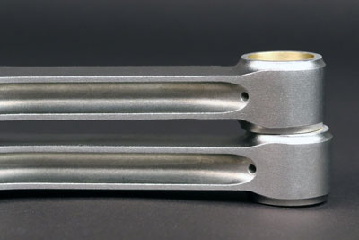


 Print
Print  Email
Email


 Thanks, Grumpy! As it happens, I am right in the middle of a long stroke small block build and I will certainly read over all the links you posted before proceeding.