connecting rod & rod length too stroke info

Re: bore to stroke ratio

:D Thanks for the cam recommendations and timing card location info, Grumpy! I ran the Crower cams through Dyno 2003 with my 427 engine combo specs. Used valve lift with 1.6 rockers as suggested.

Of the 2 Crower grinds, my engine combo favours the larger of the 2 cams (00273S). Here are the figures I got.......


------RPMs----- HP ---TQ

2,000 RPMs - 178 - 466 - Cam, Crower 00258S hydraulic, flat tappet, 236 deg. int./242 deg. exh. @ 0.050", 106 deg. LSA, 0.479" int. / 0.475" exh. lift at valve
2,500 RPMs - 228 - 479 - Note: lift shown is with 1.6 rockers
3,000 RPMs - 282 - 493 - Peak HP - 425 @ 5,000 RPMs
3,500 RPMs - 338 - 508 - Peak TQ - 508 ft./lb. @ 3,5000 RPMs
4,000 RPMs - 387 - 508
4,500 RPMs - 416 - 486
5,000 RPMs - 425 - 446 - Avg. HP - 2,000 to 4,000 RPMs, 282.6
5,500 RPMs - 419 - 400 - Avg. TQ - 2,000 to 4,000 RPMs, 490.8 ft./lb.
6,000 RPMs - 395 - 346

------RPMs----- HP ---TQ

2,000 RPMs - 170 - 447 - Cam, Crower 00273S hydraulic, flat tappet, 239 deg. int./248 deg. exh. @ 0.050", 107 deg. LSA, 0.539" int. / 0.547" exh. lift at valve
2,500 RPMs - 225 - 473 - Note: lift shown is with 1.6 rockers
3,000 RPMs - 285 - 499 - Peak HP - 510 @ 5,500 RPMs
3,500 RPMs - 352 - 528 - Peak TQ - 546 ft./lb. @ 4,500 RPMs
4,000 RPMs - 415 - 544
4,500 RPMs - 468 - 546
5,000 RPMs - 496 - 521 - Avg. HP - 2,000 to 4,000 RPMs, 289.4
5,500 RPMs - 510 - 487 - Avg. TQ - 2,000 to 4,000 RPMs, 498.2 ft./lb.
6,000 RPMs - 502 - 439


Also ran the 2 Crane solid lifter cams mentioned on your link here......

viewtopic.php?f=52&t=1070


------RPMs----- HP ---TQ

2,000 RPMs - 163 - 427 - Cam, Crane 110921 solid, flat tappet, 244 deg. int./252 deg. exh. @ 0.050", 106 deg. LSA, 0.518" int. / 0.536" exh. lift at valve
2,500 RPMs - 217 - 456 - Note: 1.6 rockers raise peaks by 4 - 5 HP & ft./lb. TQ, but power at lower RPMs remains the same (used 1.5 rockers for simulation)
3,000 RPMs - 275 - 482 - Peak HP - 509 @ 5,500 RPMs
3,500 RPMs - 343 - 514 - Peak TQ - 539 ft./lb. @ 4,500 RPMs
4,000 RPMs - 407 - 535
4,500 RPMs - 462 - 539
5,000 RPMs - 492 - 517 - Avg. HP - 2,000 to 4,000 RPMs, 281
5,500 RPMs - 509 - 486 - Avg. TQ - 2,000 to 4,000 RPMs, 482.8 ft./lb.
6,000 RPMs - 504 - 441


------RPMs----- HP ---TQ

2,000 RPMs - 166 - 435 - Crane 114681 solid, flat tappet, 244 deg. int./252 deg. exh. @ 0.050", 112 deg. LSA (per DD2003), 0.518" int. / 0.536" exh. lift at valve
2,500 RPMs - 220 - 463 - Note: 1.5 rockers used for simulation
3,000 RPMs - 279 - 488 - Peak HP - 511 @ 5,500 RPMs
3,500 RPMs - 345 - 518 - Peak TQ - 546 ft./lb. @ 4,500 RPMs
4,000 RPMs - 413 - 542
4,500 RPMs - 468 - 546
5,000 RPMs - 500 - 525 - Avg. HP - 2,000 to 4,000 RPMs, 284.6
5,500 RPMs - 511 - 528 - Avg. TQ - 2,000 to 4,000 RPMs, 489.2 ft./lb.
6,000 RPMs - 504 - 441


And here are the figures I got for the 2 Isky cams that came out best in prior calculations.....


------RPMs----- HP ---TQ

2,000 RPMs - 187 - 491 - Cam, Isky 274 Mega hydraulic, flat tappet, 226 deg. int./226 deg. exh. @ 0.050", 108 deg. LSA, 0.490" lift at valve (both)
2,500 RPMs - 243 - 510 - Note: 1.6 rockers raise peaks by 4 - 5 HP & ft./lb. TQ, but power at lower RPMs remains the same (used 1.5 rockers for simulation)
3,000 RPMs - 302 - 528 - Peak HP - 478 @ 5,000 RPMs
3,500 RPMs - 362 - 543 - Peak TQ - 547 ft./lb. @ 4,000 RPMs
4,000 RPMs - 417 - 547
4,500 RPMs - 458 - 535
5,000 RPMs - 478 - 502 - Avg. HP - 2,000 to 4,000 RPMs, 302.2
5,500 RPMs - 468 - 447 - Avg. TQ - 2,000 to 4,000 RPMs, 523.8 ft./lb.
6,000 RPMs - 446 - 390

------RPMs----- HP ---TQ

2,000 RPMs - 184 - 483 - Cam, Isky 530-A solid, flat tappet, 242 deg. int./246 deg. exh. @ 0.050", 106 deg. LSA, 0.530" int./ 0.535" lift at valve
2,500 RPMs - 239 - 501 - Note: 1.5 rockers used for simulation
3,000 RPMs - 297 - 520 - Peak HP - 517 @ 5,500 RPMs
3,500 RPMs - 359 - 538 - Peak TQ - 548 ft./lb. @ 4,500 RPMs
4,000 RPMs - 417 - 548
4,500 RPMs - 470 - 548
5,000 RPMs - 505 - 530 - Avg. HP - 2,000 to 4,000 RPMs, 299.2
5,500 RPMs - 517 - 493 - Avg. TQ - 2,000 to 4,000 RPMs, 518 ft./lb.
6,000 RPMs - 509 - 446


The Isky cams were run with 1.5 rockers, as I tried 1.6 on intake only, then 1.6 on exhaust only and then 1.6 for both. Power remained the same over the lower RPMs and showed only a small increase (4 - 5 HP & ft./lb. TQ) at peak TQ and HP with 1.6 rockers on both.

The Crower cams were run with valve lift calculated for 1.6 rockers as suggested.

The Crane cams were run with 1.5 rockers, as I tried 1.6 on intake only, then 1.6 on exhaust only and then 1.6 for both. Power remained the same over the lower RPMs and showed only a small increase (4 - 5 HP & ft./lb. TQ) at peak TQ and HP.

I have ranked the 2 Isky, the 2 Crower and the 2 Crane cams below by how they came out based upon average HP and TQ between 2,000 and 4,000 RPMs (the engine speeds my engine will see most out on the road)......


Isky 274 Mega hydraulic, flat tappet, 226 deg. int./226 deg. exh. @ 0.050", 108 deg. LSA, 0.490" lift at valve (both)

Peak HP - 478 @ 5,000 RPMs
Peak TQ - 547 ft./lb. @ 4,000 RPMs

Avg. HP - 2,000 to 4,000 RPMs, 302.2
Avg. TQ - 2,000 to 4,000 RPMs, 523.8 ft./lb.


Isky 530-A solid, flat tappet, 242 deg. int./246 deg. exh. @ 0.050", 106 deg. LSA, 0.530" int./ 0.535" lift at valve

Peak HP - 517 @ 5,500 RPMs
Peak TQ - 548 ft./lb. @ 4,500 RPMs

Avg. HP - 2,000 to 4,000 RPMs, 299.2
Avg. TQ - 2,000 to 4,000 RPMs, 518 ft./lb.


Crower 00273S hydraulic, flat tappet, 239 deg. int./248 deg. exh. @ 0.050", 107 deg. LSA, 0.539" int./0.547" exh. lift at valve

Peak HP - 510 @ 5,500 RPMs
Peak TQ - 546 ft./lb. @ 4,500 RPMs

Avg. HP - 2,000 to 4,000 RPMs, 289.4
Avg. TQ - 2,000 to 4,000 RPMs, 498.2 ft./lb.


Crower 00258S hydraulic, flat tappet, 236 deg. int./242 deg. exh. @ 0.050", 106 deg. LSA, 0.479" int./0.475" exh. lift at valve

Peak HP - 425 @ 5,000 RPMs
Peak TQ - 508 ft./lb. @ 3,5000 RPMs

Avg. HP - 2,000 to 4,000 RPMs, 282.6
Avg. TQ - 2,000 to 4,000 RPMs, 490.8 ft./lb.


Crane 114681 solid, flat tappet, 244 deg. int./252 deg. exh. @ 0.050", 112 deg. LSA (per DD2003), 0.518" int. / 0.536" exh. lift at valve

Peak HP - 511 @ 5,500 RPMs
Peak TQ - 546 ft./lb. @ 4,500 RPMs

Avg. HP - 2,000 to 4,000 RPMs, 284.6
Avg. TQ - 2,000 to 4,000 RPMs, 489.2 ft./lb.


Crane 110921 solid, flat tappet, 244 deg. int./252 deg. exh. @ 0.050", 106 deg. LSA, 0.518" int. / 0.536" exh. lift at valve

Peak HP - 509 @ 5,500 RPMs
Peak TQ - 539 ft./lb. @ 4,500 RPMs

Avg. HP - 2,000 to 4,000 RPMs, 281
Avg. TQ - 2,000 to 4,000 RPMs, 482.8 ft./lb.


As you predicted, of the 2 Crane cams, the Dyno 2003 program favoured the wider LSA version of the same cam.

Not sure why the Isky cam grinds made more comparative power than did the Crower and Crane grinds (in the RPM range my engine will be run at most), but my engine combo seems to respond better to the Isky cams, at least in computer simulation. And as you say, real world performance may vary.

Really appreciate your assistance, Grumpy!

Best regards,

Harry
 
Re: bore to stroke ratio
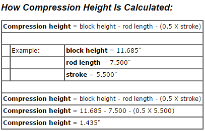
compheighty.png

I,d doubt you'll be disappointed with any of the better selections, but if you do get the car dyno tested after its tuned it will be interesting to compare the real world results with the dd dyno predicted wild guess the software shows
 
Last edited by a moderator:
Re: bore to stroke ratio

:D I agree, Grumpy! It will be very interesting to see how this works out in terms of real world TQ and HP at the planned operating range. FWIW...... I plan on using this engine as a test bed to see how several intake systems work, including a home brewed IR intake. It will be a while before the car is ready to go, but I will keep in touch and let you know how things are progressing.

There may be some compromises required when fabbing the exhaust system because I do not want the hassle of header leaks on a road car with full length, muffled exhaust. Nor do I want to fry starters nor have engine oil temps increase due to oil filter and header clearance issues.

On the other hand...... As I have made the decision to build this engine for torque and keep RPMs down...... I may be able to get the sizing I need in heavy wall tubing and fit it as I have in mind after all. At present, I am thinking in terms of welded thickwall upswept headers similar in function to the old MOPAR Max Wedge cast headers of the early '60s. These were actually a 4 - 2 - 1 Tri-Y design and I believe something similar would enhance torque all the more.

Best regards,

Harry

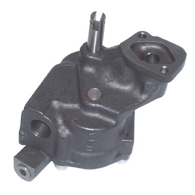
BTW...... I am thinking about going to a standard volume big block oil pump. I understand from speaking to several engine builders that Melling and others they make pumps for to sell under their brand name have gone through several production changes in recent years. First, they began utilizing thinner pump body castings sourced from the ChiComs with the result that a high percentage of pumps used in performance and heavy duty applications developed cracks in the pump bodies.

Then they tried to get by with powdered metal pump gears...... Which also didn't work out well, either. I understand that they are working their way back to building pumps as they once did...... But that there are still pumps in warehouses that have the thin body castings and / or the powdered metal gears. My dilemma is where to get a really good and reliable oil pump and shaft that will last the life of this engine. Any ideas?
 
Re: bore to stroke ratio

http://www.moroso.com/catalog/categoryd ... code=17006

http://www.melling.com/Aftermarket/High ... Pumps.aspx
watch this video
http://www.summitracing.com/parts/MEL-10778/?rtype=4

the melling 10990 is generally a well built pump but the price has gone up significantly since they started building them correctly again.
its basically a big block 5 bolt pump set up to run in a small block application
Ive run them in most of my sbc engines built recently and its in my corvettes 383

mel-10990_w.jpg


http://www.summitracing.com/parts/MEL-10990/

btw

10778 used for big block engines

http://www.summitracing.com/parts/MEL-10778/
 
Re: bore to stroke ratio

:D Thanks, Grumpy! That's good info. With the 383 small block applications you build, do you keep the spring that comes in the 10990 pump or replace it with the supplied standard pressure spring?

And have you used the 10990C (version with the anti-cavitation grooves)? On a mostly street driven application, I am a bit leery of the stated 'reduces pressure at idle'.

http://www.melling.com/Aftermarket/High ... Pumps.aspx

10990

* High volume performance upgrade for the M-99HV-S.
* Increase in volume of 25% over stock oil pump.
* The 10990 is a Big Block style oil pump made to fit the Small Block applications.
* The drive and idler shafts have been extended to allow for additional support in the cover. Additional support eliminates dynamic shaft deflection at increased RPM levels.
* The cover is doweled to the pump housing to assure alignment of the shaft bores.
* The relief valve has a screw-in plug instead of a pin.
* The housing and cover are CNC machined and phosphate coated.
* An additional spring, the original stock replacement is supplied which will reduce bypass pressure if needed.
* Includes intermediate shaft with steel guide.
* Uses 3/4” press in screen.
* Patent No. 5,810,571.

10990C (Anti-Cavitation)

* High volume performance upgrade for the M-99HV-S.
* Increase in volume of 25% over stock oil pump.
* The same as the 10990 except with the addition of grooves machined in the housing and cover. The grooves reduce cavitation effects in high RPM applications.
* Using this oil pump will reduce pressure at idle.
* Includes intermediate shaft with steel guide.
* Uses 3/4” press in screen.
* Racing applications only.
* Patent No. 5,810,571.

I have a 7 quart Moroso #20190 pan with kickouts on both sides. It is 8-1/4" deep......

http://www.moroso.com/catalog/categoryd ... code=11002

In the notes, Moroso oil pickup #24320 is spec'd for big block oil pumps, so am I right in assuming that this would be the correct pickup to use with the Melling 10990 pump and this pan?

I see that Moroso now has pans notched for strokes over 3.80" as well. I will hold off until I have clearanced my block, trial fitting the crank and pistons and oil pan to see if my #20190 pan will work. But if not, I will likely go to the #20195 pan that has the same dimensions, but is notched for longer stroke crank throws.

Best regards,

Harry
 
Re: bore to stroke ratio

enigma57 said:
:D Thanks, Grumpy! That's good info. With the 383 small block applications you build, do you keep the spring that comes in the 10990 pump or replace it with the supplied standard pressure spring?
I use the lower pressure spring

And have you used the 10990C (version with the anti-cavitation grooves)? On a mostly street driven application, I am a bit leery of the stated 'reduces pressure at idle'.

http://www.melling.com/Aftermarket/High ... Pumps.aspx

10990

* High volume performance upgrade for the M-99HV-S.
* Increase in volume of 25% over stock oil pump.
* The 10990 is a Big Block style oil pump made to fit the Small Block applications.
* The drive and idler shafts have been extended to allow for additional support in the cover. Additional support eliminates dynamic shaft deflection at increased RPM levels.
* The cover is doweled to the pump housing to assure alignment of the shaft bores.
* The relief valve has a screw-in plug instead of a pin.
* The housing and cover are CNC machined and phosphate coated.
* An additional spring, the original stock replacement is supplied which will reduce bypass pressure if needed.
* Includes intermediate shaft with steel guide.
* Uses 3/4” press in screen.
* Patent No. 5,810,571.

10990C (Anti-Cavitation)

* High volume performance upgrade for the M-99HV-S.
* Increase in volume of 25% over stock oil pump.
* The same as the 10990 except with the addition of grooves machined in the housing and cover. The grooves reduce cavitation effects in high RPM applications.
* Using this oil pump will reduce pressure at idle.
* Includes intermediate shaft with steel guide.
* Uses 3/4” press in screen.
* Racing applications only.
* Patent No. 5,810,571.

I have a 7 quart Moroso #20190 pan with kickouts on both sides. It is 8-1/4" deep......

http://www.moroso.com/catalog/categoryd ... code=11002

In the notes, Moroso oil pickup #24320 is spec'd for big block oil pumps, so am I right in assuming that this would be the correct pickup to use with the Melling 10990 pump and this pan?

ALWAYS VERIFY WHAT COMPONENTS ARE TO BE MATCHED IN ANY APPLICATION ,WITH THE MANUFACTURERS ,and ALWAYS ASK IF THEY HAVE OTHER RELATED TIPS,INFO, or RELATED WARNINGS but yes your more than likely correct but as Ive stated ..ALWAYS ASK[/b]

I see that Moroso now has pans notched for strokes over 3.80" as well. I will hold off until I have clearanced my block, trial fitting the crank and pistons and oil pan to see if my #20190 pan will work. But if not, I will likely go to the #20195 pan that has the same dimensions, but is notched for longer stroke crank throws.

Best regards,

Harry

hope that helps
 
Re: bore to stroke ratio

Yes, thanks, Grumpy! This helps a lot. I figured the big block style pump with the lower (normal) pressure spring would be the way to go and I will verify the info on pickup tube and screen after I clearance my block and see if my 20190 pan will work with the increased stroke.

Many thanks,

Harry
 
Re: connecting rod info

http://www.circletrack.com/enginetech/c ... index.html

http://www.carcraft.com/techarticles/11 ... index.html

http://www.eaglerod.com/mosmodule/bolt_torque.html
Chevy V8 bore & stroke chart
I saw this online and figured I would post it..I am going to add the popular lsx strokers soon
CID BORE STROKE
262 = 3.671" x 3.10" (Gen. I, 5.7" rod)
265 = 3.750" x 3.00" ('55-'57 Gen.I, 5.7" rod)
265 = 3.750" x 3.00" ('94-'96 Gen.II, 4.3 liter V-8 "L99", 5.94" rod)
267 = 3.500" x 3.48" (Gen.I, 5.7" rod)
283 = 3.875" x 3.00" (Gen.I, 5.7" rod)
293 = 3.779" x 3.27" ('99-later, Gen.III, "LR4" 4.8 Liter Vortec, 6.278" rod)
302 = 4.000" x 3.00" (Gen.I, 5.7" rod)
305 = 3.736" x 3.48" (Gen.I, 5.7" rod)
307 = 3.875" x 3.25" (Gen.I, 5.7" rod)
325 = 3.779" x 3.622" ('99-later, Gen.III, "LM7", "LS4 front wheel drive V-8" 5.3 Liter Vortec, 6.098" rod)
327 = 4.000" x 3.25" (Gen.I, 5.7" rod)
345 = 3.893" x 3.622" ('97-later, Gen.III, "LS1", 6.098" rod)
350 = 4.000" x 3.48" (Gen.I, 5.7" rod)
350 = 4.000" x 3.48" ('96-'01, Gen. I, Vortec, 5.7" rod)
350 = 3.900" x 3.66" ('89-'95, "LT5", in "ZR1" Corvette 32-valve DOHC, 5.74" rod)
364 = 4.000" x 3.622" ('99-later, Gen.III, "LS2", "LQ4" 6.0 Liter Vortec, 6.098" rod)
376 = 4.065" x 3.622" (2007-later, Gen. IV, "L92", Cadillac Escalade, GMC Yukon)
383 = 4.000" x 3.80" ('00, "HT 383", Gen.I truck crate motor, 5.7" rod)
400 = 4.125" x 3.75" (Gen.I, 5.565" rod)
427 = 4.125" x 4.00" (2006 Gen.IV, LS7 SBC, titanium rods)

Two common, non-factory smallblock combinations:

377 = 4.155" x 3.48" (5.7" or 6.00" rod)
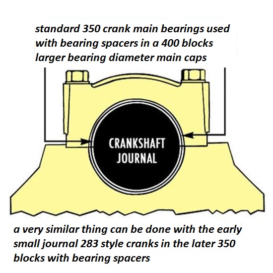
400 block and a 350 crank with "spacer" main bearings
383 = 4.030" x 3.75" (5.565" or 5.7" or 6.0" rod)
350 block and a 400 crank, main bearing crank journals
cut to 350 size

ALL production big blocks used a 6.135" length rod.
CHEVY BIG BLOCK V-8 BORE AND STROKE


366T = 3.935" x 3.76"
396 = 4.096" x 3.76"
402 = 4.125" x 3.76"
427 = 4.250" x 3.76"
427T = 4.250" x 3.76"
454 = 4.250" x 4.00"
477= 4.5" bore x 3.76" stroke
496 = 4.250" x 4.37" (2001 Vortec 8100, 8.1 liter)
502 = 4.466" x 4.00"
557T= 4.5 bore 4.375" stroke
572T = 4.560" x 4.375" (2003 "ZZ572" crate motors)

T = Tall Deck
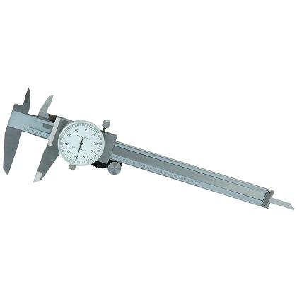
always accurately measure the crank main journals, and remember the crank and block bearing sizes on a 400 sbc and 350 smc are different as are the early 283-327 sbc
spacerbearing5a.jpg

calipersaa.jpg

ALL production big blocks used a 6.135" length rod.
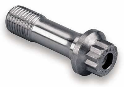
Fasteners, no matter what type, are the greatest weakness in a connecting rod. However, if installed correctly, most fasteners from quality manufacturers are capable of handling the stresses they are designed for.
most engine failures ,Ive seen that were blamed on connecting rods are not truly the result of the connecting rods failing but either improper assembly or its been the valve train or lubrication system that failed resulting in the rods being damaged, drop a valve and you can,t expect the rod to compress a solid steel valve into a cylinder head without being over stressed and bending, loose lubrication, the bearings cooling and load supporting oil film disappears and the bearings spin, the rod gets slack, the piston starts slapping the heads, and disaster follows in seconds.
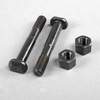
The fasteners used to hold the two pieces of the big end of the rod together come in two designs. Thru-bolt designs have a complete bolt and nut to clamp the rod together. A cap-screw design eliminates the nut, instead utilizing threads in the rod for the bolt to thread into. A thru-bolt design requires flat faces to be cut into the big end of the rod for each bolt (one for the head of the bolt and one for the nut). Eliminating the flat for the nut makes the cap screw that much stronger. Additionally, threading the bolt directly into the body of the rod also helps rigidity.
Torque vs. Stretch
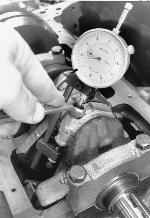
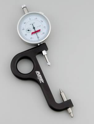
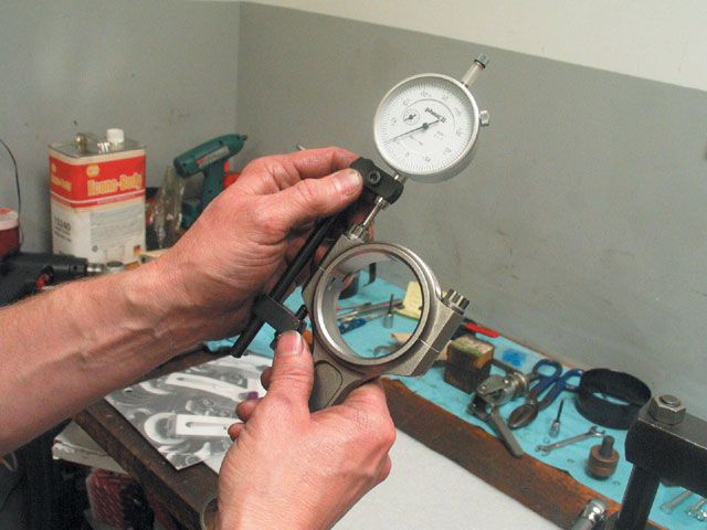
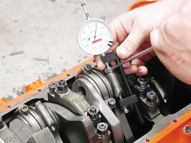
The torque spec applied to any particular fastener is merely an estimate of the twisting force required to achieve the correct amount of preload or clamp load. Many times this is the only way to apply fastener load because the bolt threads into a blind hole like in the cylinder block. One advantage to the rod bolt is that both ends of the bolt can be accessed. This allows you to use a rod bolt stretch gauge. This is a specialty tool sold through companies like ARP that will accurately measure the amount of bolt stretch.

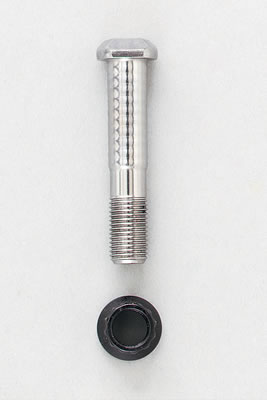
The procedure is actually quite simple. Once the connecting rod and cap are installed on the crank, start a nut on the rod bolt, slip on the appropriate-size box-end wrench, and then install the stretch gauge. All ARP connecting rod bolts have a small dimple placed on both ends of the bolt that accurately position the rod bolt gauge pins on the bolt. Next, zero the gauge on the relaxed bolt. Then you carefully tighten the rod bolt until the gauge reads the appropriate stretch amount. For example, a standard 11/32-inch ARP small-block Chevy specs out at 0.0063 inch.


http://www.circletrack.com/tipstricks/4 ... index.html

p117194_image_large.jpg

arp-100-9942_w.jpg

ctrp_0311.jpg

116_0609_rod07_z.jpg

116_0609_rod06_z.jpg


Do not assume all the rod bolts will all take the same torque to get to the specified listed stretch

cbrb6.jpg

cbrb5.jpg

cbrb3.jpg

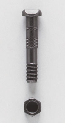
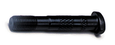
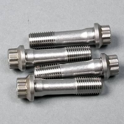
THE stock and less expensive replacement rod bolts pictured above tend to be made of less expensive materials, rod bolts with knurled shanks tend to be weaker than the ARP WAV LOC designs but check out the rated stress and torque levels
and remember bolts with 7/16" cap screws (ARP 2000) tend to be more rigid than bolts requiring locking nuts
most QUALITY aftermarket rod bolts, and rods with cap screw fasteners will have, the cap screws thread into the main connecting rod body without nuts, or NUTS or bolt heads that will be of the 12 point design vs the stock 6 point nuts, and pull thru bolt design


cbrb1.jpg

cbrb2.jpg

cbrb4.jpg
 
Last edited by a moderator:
Re: bore to stroke ratio

The Confusion Factor - A Collection of Misunderstood Ideas and Terms By B. Rawls


Camshaft Overlap and Compression
Exhaust System Diameter and Engine Horsepower
Lobe Separation Angle and Engine Usage
Custom Ground Camshafts
Old Camshafts Lacked Sound Design Principles
Degreeing Camshafts
Rocker Arm Ratios
Piston to Valve Clearance
Adjusting Lash on Mechanical/Solid Cams
Hydraulic Lifter Preload and Pump-Up
Pushrod Length and Valve Stem Centerline


Camshaft Overlap and Compression- A very common idea, although for the most part incorrect, is that overlap bleeds off compression. Overlap, by itself, does not bleed off compression. Overlap is the angle between the exhaust closing and intake opening and is used to tune the exhaust's ability draw in additional intake charge as well as tuning idle vacuum and controlling power band width. Cylinder pressure is generated after the intake valve has closed, through the ignition process, and before the exhaust opens; in other words the compression cycle and ignition cycle of the 4 cycle or 4 stroke engine. Within practical limits, an early intake closing and late exhaust opening will maintain the highest cylinder pressure. Overlap can be increased by narrowing the Lobe Separation Angle while holding the intake and exhaust lobe duration constant. In doing so, the cylinder pressure or dynamic compression can actually increase as the earlier intake closing pairs up with the delayed exhaust opening. Overlap can also be increasing by widening intake and exhaust lobe duration while the Lobe Separation Angle is held constant. This decreases cylinder pressure or bleeds off compression. In both scenarios the overlap was increased, but the outcome differs as the intake closing and exhaust opening relationships change. The true culprit that bleeds off compression is the whole collection of valve events, not just overlap.


Exhaust System Diameter and Engine Horsepower- A popular idea is to select or size the exhaust system components to the engine's horsepower output. This methodology attributes a header diameter or an exhaust system diameter to a particular horsepower level. To debunk this idea, look at how an engine operates and consider one cylinder. The amount of charge that can enter the cylinder is dependent on inlet flow capability, crank geometry, rpm, and valve timing as a minimum consideration. Likewise, the amount of spent charge exiting the cylinder is dependent on the same characteristics.

An engine's output is usually thought of in terms of horsepower. Actually, an engine produces work, measured as torque on a dynamometer, and the horsepower is calculated through a units conversion. The amount of torque an engine produces is directly related to the amount of cylinder pressure generated. Once again, this is all affected by the same previous characteristics (flow capability, crank geometry, rpm, valve timing, etc). Therefore, an engine's power output is about air exchange and cylinder pressure. Using this line of thinking, reconsider the exhaust path. The exhaust system is more reflective of the engine's ability to move air, as opposed to horsepower numbers. Engine output does not address the breathing aspects of the engine and is not a good criteria to use for exhaust sizing.

There is a very good reason that tuners/engineers/specialist have attempted to assign exhaust to intake relationships around 70-80% for a typical natural aspirated set-up. In non-detailed terms, it is a range that offers a good balance for power capability. Other relationships, such as 1:1, are used and they work very well, but these methods have to be applied and tuned for very specific circumstances. This relationship does not stop on the flow bench on a lone cylinder head; it applies all the way from the intake path opening to the exhaust system termination. In short, try to maintain exhaust sizes that are in line with the intake flow capability. Also, do not stop your analysis at the intake and exhaust paths. If the engine already has the camshaft, look at the valve events. If the specs favor a restricted exhaust (indicated by early and wider exhaust openings with wider lobe separation angles), then size it accordingly by using exhaust components with smaller cross-sections. If the valve timing specs favor the intake, then the engine needs some serious exhaust flow capability, which is only possible with larger cross-sections.

This section was written with natural aspirated combinations in mind. However, by using the 'air exchange' rationale, it becomes apparent why forced induction engines typically benefit from increased exhaust flow capability. Also, look at the nitrous combinations. The intake system remains virtually unchanged, yet with the major increases in cylinder pressure it acts like a substantially larger engine on the exhaust side, requiring earlier exhaust openings and/or higher exhaust flow capability.


Lobe Separation Angle and Engine Usage- There are many terms associated with camshafts that get tossed around often. Lobe Separation Angle (LSA) is a term that receives a lot of attention, but mostly incorrectly. For some reason, when cam application and selection is discussed, LSA seems to come first and gets linked to engine usage. Categorically, narrow LSAs are associated with racing applications with narrow/peaky operating ranges. Wide LSA’s are associated with streetability, broad powerband response, and exhaust emissions. A very effective argument to this approach is to inquire about camshafts used in Pro-Stock and Competition Eliminator drag sanctioned classes that utilize Lobe Separation Angles around 114 degrees, and occasionally in the 116 to 118 degree range. These are racing engines that can achieve 3 hp/cid and have powerbands that are often within a narrow 2000 rpm envelope; clearly violating the LSA selection guidelines. Another approach might be to compare a 283 cid Chevrolet Super Stock to a 280 cid Chevrolet Competition Eliminator. The camshaft on the Super Stock application might have a 104 LSA, while the Comp Eliminator has a 114 LSA.

These examples reveal a key piece of info regarding LSA. If you really look at the engine combinations, the more breathing capability a motor has (relative to its displacement), the wider the LSA can end up. This observation indicates that LSA and engine usage comparisons are not globally valid. If it is so easy to point out very well established examples that violate the criteria, maybe the premise of LSA versus engine usage (void of specific engine parameters) is not a valid cam selection criterion at all.

Another key piece of info is that different engine combinations require completely different valve events. Once those valve events are determined, and lobe requirements are established, the LSA is calculated, and the camshaft can be manufactured. Maybe, LSA should be thought of as a camshaft manufacturing term as opposed to a camshaft design criteria.


Custom Ground Camshafts- When optimized performance of an engine combination is desired, the camshaft design parameters are calculated from the engine and vehicle specifications to perform within specific operating conditions. Let me emphasize that last statement, 'within specific operating conditions'. In no way was total maximum power for the engine implied. The intent is to maximize performance within the intended design parameters. If that means taking a pro-stock motor and wanting to run it from 2000-5000 rpm, then so be it.

The camshaft's seat timing events, ramp rate, and lift are directly related to the intake and exhaust flow capabilities, crankshaft geometry, static compression, rpm range, as well as other criteria. A camshaft selected in this manner, becomes personalized to that particular engine combination. Usually a custom grind is selected as an intake lobe and exhaust lobe with a particular phasing to each other (lobe separation angle, LSA) and sometimes a specified amount of advance or retard is built in. Although, it could easily end up having completely reengineered lobe characteristics, requiring new lobe masters with specialized ramp requirements. It is possible for an off-the-shelf camshaft to be a classified as a 'custom'. If the cam design is calculated for a particular combination and an off-the-shelf part number fits the bill, then for all practical purposes that part number is a 'custom' cam (but only for that particular set-up).

Typically, cam catalogs do not specifically list custom ground camshafts, because the possibilities are endless. They stick to particular series or families of camshafts. The super stock grinds come closest to an off-the-shelf grind that is truly optimized for a combination. There will be small differences due to header sizes and engine builders’ secrets, but usually the catalogs are pretty close to a good baseline. Likewise, brand to brand, the grinds will be very similar because of the 'class' dictated combinations and the flow characteristics are so well documented.


Old Camshafts Lacked Sound Design Principles- To quote Chevy High Performance’s Cam-Tastic! Issue from March 2000, Camshaft Basics, “In the old days of camshaft design most cams were designed with exactly the same duration on the intake and exhaust lobes”.

I have seen other articles and books make similar claims. It is time to cut to the chase on this and clear the air of misinformation. Real camshaft design has always addressed the needs of the engine. It’s the high performance marketplace that, for some reason, skirted the whole idea of what the camshaft does, adopting this same intake and exhaust lobe subject line. Therefore, they are the ones staking claim to noticing the change over the past 20 or so years. In short, real engineering design in valve events and camshaft technology has always been around. Here a few examples:

In the 1930s, the Chevrolet Brothers’ Frontenac Stagger-Valve cylinder head conversion utilized 7 degrees more intake duration than exhaust.

In the late 1940s, Offenhauser was using cams with different intake and exhaust lobes on their speedway motors.

In 1959, Almquest Engineering (pioneers in the hot rod mail order business, beginning in the 1940s) offered different camshaft grinds for the flathead Ford V8’s, and some of those utilized more exhaust lobe duration.

In 1966, Ford designed the camshaft for its 289 Trans-Am Program that utilized 14 degrees less exhaust seat duration, to match the 90% exhaust to intake ratio of the seriously hogged out exhaust ports with 1.625 valves.

The Z-28 “Special Off-Road” Camshaft utilized more than 10 degrees of additional exhaust duration.

For an article entitled “Camshaft Basics”, it missed some relevant history. The article claims the design process changed over the years. Technology has certainly advanced, but the design process of matching the camshaft to the motor hasn’t.


Degreeing Camshafts- There is no special magic involved for degreeing a camshaft during installation, but this is not the same thing as random advancing, retarding, or installing the gears 'lined up'. Degreeing a camshaft involves definite known values for valve events. Typically this is specified as an Intake Centerline or as opening/closing events at specific lobe lifts. This is done to insure the cam is installed per specific requirements, such as a recommendation from an engine builder or the vendor's data sheet for that camshaft grind. Manufacturing tolerances and shop practices do not guarantee that the cam matches the data sheet, when installed at crank gear 'zero'. The cam will usually need to be advanced or retarded to the correct location. If it is correct, at crank gear 'zero', then the cam has still been degreed. It just did not require any additional tweaking to meet the requirements. Verifying the installation is what degreeing a cam is all about. A common misused term is the 'straight-up' installation. Typically this is described as installing the cam at crank gear 'zero'. This is 100% wrong. ‘Straight-up’ refers to the intake and exhaust centerlines being the same. In other words the cam will have no advance or retard during installation, regardless of the amount of advance/retard ground in by the vendor. In reality, the cam may have to be advanced or retarded (from crank gear 'zero') significantly to arrive at a ‘straight-up’ position.


Rocker Arm Ratios- What is the role of the valve rocker arms in an engine? Rocker arms redirect the line of action of the camshaft's lifters or followers to the valve stems' centerline. Most rocker arms utilize a design that multiplies the camshaft lobe profile providing an amplified path that the valves follow. This multiplier is called the rocker arm ratio.


A camshaft lobe profile is measured in lift per degrees of crankshaft rotation. The typical lobe profile graph will have a vertical axis in lift increments (inches or mm) and a horizontal axis in terms of crankshaft rotation (degrees). This data forms the specs that camshaft lobes are described by. It will be stated as degrees of lobe duration at a specific lobe lift. Similarly, the valves, acted on by the rocker arm, can be measured in degrees of crankshaft rotation at a specific valve lift. This duration can be decribed as valve duration. Altering the rocker arm ratio changes the multiplication effect. The crankshaft rotation for a given valve lift will be changed from its original baseline positioning; in other words, the valve duration changes. Most often, we read that rocker arm ratio changes only affect the maximum valve lift; this is incorrect and impossible. By definition, all points where lobe lift occurs are translated to the valves through the rocker arm ratio. The change in valve duration that occurs due to the rocker arm ratios has to be decoupled from the camshaft lobe specs. These are two completely different measurements, yet intrinsically related because of the rocker arm. The valve duration changes, obviously the camshaft lobe duration does not.


A higher ratio will increase the valve lift per degree of crankshaft rotation. Therefore, the crankshaft will reach a given valve lift opening point earlier and closing point later; increasing the valve duration at the specific valve lift. Increasing the rocker arm ratio increases valve duration.

A lower ratio will decrease the valve lift per degree of crankshaft rotation. Therefore, the crankshaft will reach a given valve lift opening point later and closing point earlier; decreasing the valve duration at the specific valve lift. Decreasing the rocker arm ratio decreases valve duration.

Here is a graphical depiction of the lobe profile versus valve activity with differing rocker arm ratios.


Piston To Valve Clearance- Piston clearance is a function of lobe geometry and phasing to the piston. Cam lift should not be a deciding a factor in clearance issues. Valves will hit the piston in the overlap period, while exhaust is closing and intake is opening. Exhaust clearance problems will typically occur just before TDC and intake just after TDC, not at max lift. Some cylinder head venders and other component manufacturers advertise a max duration or lift before clearance issues arise. This is very misleading. Maximum safe duration is a totally bogus value, and is completely worthless without knowing anything about the ramp rates or actual timing/phasing events of the installation. At least with maximum safe lift, the vendor can apply a ridiculously fast ramp at a very early opening/closing and arrive at a somewhat meaningful measurement, but without knowing the design specifics the information is still next to useless.


Adjusting Lash on Mechanical/Solid Cams- If valve lash changes significantly over time, then something is wrong. Cam wear is very slight, along the order of .002 or less. Lash settings should be taken/adjusted at the same temperature and same order as the previous or original setting. This is the only way to rule out expansion/contraction of the components from temperature changes. This temperature delta is usually the culprit of most valve lash dilemmas. At initial start-up and break-in of a new set-up: cam, lifters, rockers, pushrods, valve job, etc., the lash may move around during the break-in procedure and for a short time after. This is because all the parts are seating into their new wear patterns. Once this occurs, the lash setting should stay steady. If lash settings change more than .005” then there has been a component failure (loosened hardware or actual mechanical failure)


Hydraulic Lifter Preload and Pump-Up- Hydraulic lifters are intended to make up for valvetrain dimensional differences as well as providing a self-adjusting method of maintaining valve lash, or rather the lack of. By setting the valvetrain so the lifter plunger is depressed slightly, the lifter is able to compensate for these differences, making a convenient hassle-free valvetrain set-up. For performance applications, lifter preload is not needed or wanted. As rpm's increase, the lifter has a tendency to bounce over the back of the lobe as it comes back down from the maximum lift point. The pressurized oil fills the lifter body to account for this bouncing. Eventually, after several engine revolutions (fractions of a second), the oil can completely fill the lifter body and the plunger will be pushed up to its full travel (pump-up). Higher oil pressures can amplify this problem. With the lifter pre-loaded, this can cause a valve to run off its seat and can cause piston clearance issues if and when pump-up occurs. By setting the valvetrain preload at “zero lash”, or just beyond, as felt by the hands and fingers during the adjustment process, lifter pump up is prevented and in most cases, the cam will rev higher. This adjustment process will typically end up with about .003” to .007” of lifter preload. Ford tech and tuning articles in the late 60's actually urged 'stock' class racers to run a positive lash of .001”-.003” on hydraulic cams.


Pushrod Length and Valve Stem Centerline- Incorrect pushrod length can be detrimental to valve guide wear. Most sources say that centering the rocker contact patch on the valve stem centerline at mid valve lift is the correct method for determining the optimum pushrod length. This method is wrong and can actually cause more harm than good. The method only applies when the valvetrain geometry is correct. This means that the rocker arm lengths and stud placement and valve tip heights are all perfect. This is rarely the case. To illustrate this, think of the valve angle and the rocker stud angle. They are usually not the same. If a longer or shorter valve is installed, then the relationship of the valve tip to the rocker stud centerline has changed. Heads that have had multiple valve jobs can also see this relationship change. Notice, the rocker length (pivot to tip) remains unchanged, so the rocker contact patch will have to move off the valve centerline some particular distance for optimum geometry to be maintained.

The optimum length, for component longevity, is the length that will give the least rocker arm contact area on the valve stem. In other words the narrowest wear pattern. This assures that the relationship is optimized and the valve stem centerline is tangent to the rocker arm’s circular swept path. The optimum rocker tip contact point probably will not coincide with the valve stem centerline. What is the acceptable limit for being offset from the valve stem centerline? That will depend on the set-up. A safe margin to strive for is about +/-.080" of the centerline of an 11/32 diameter valve stem. No part of the wear pattern should be outside of this .160" wide envelope. As the pushrod length is changed, the pattern will change noticeably. As the geometry becomes closer to optimum, the pattern will get narrowest. If the narrowest pattern is too far from the valve stem centerline, then the valve to rocker relationship has to be changed. In this case, the valve stem length or the rocker arm will need to be changed. This does not imply a change of rocker ratio, but rather the sweep radius.
 
Re: bore to stroke ratio

:D A very interesting read, Grumpy! Thanks for posting!

Best regards,

Harry
 
Re: bore to stroke ratio

I'm about to start the build on a moderate 403 Olds for my 442, talk about over square...
Bore.....Stroke
4.351 x 3.385
The windowed block webbing limits overall horsepower but I only want 350-360, and for big bore short stroke motors, they make great torque if you keep the ports and valves and cam in line with the intended use. I built a very mild one in my '79 Trans Am when it was new, well really I just bolted stuff on. At the time intakes and such were a bit limited, all I did was Hooker headers with true duals (2.5"), Holley intake and 750 vacuum secondary and a set of 3.23 gears. On old Firestone SS 275/60's that thing went 13.60's- 13.80's depending on how well I got it to 60'.
 
Re: connecting rod info

Spare the Rod and Spoil the Engine
Category: Tech Talk —

Published in National Dragster

Written by David Reher

Imagine riding an elevator that makes a 10-story round trip 7,000 times a minute, alternately stretching and compressing its occupants with every cycle. That’s exactly the kind of punishing treatment a connecting rod endures. A connecting rod must bear the compression force of thousands of pounds of cylinder pressure, withstand the tension loads produced by the piston’s inertia at TDC, and survive the bending loads that try to push the piston through the cylinder wall.

The connecting rods are vital links in every reciprocating engine. They tend to be taken for granted until they break – and when a rod lets go, it will spoil your day and ruin your engine.

In drag racing, the choice of material for connecting rods comes down to steel and aluminum. I’m not privy to the inner workings of Formula 1 racing engines, but we did experiment with titanium connecting rods in our Pro Stock engines a few years ago. While titanium has some appealing attributes, it also has some shortcomings when used as a connecting rod material. The necessity to coat the thrust surfaces, the expense of machining and tooling, and the problems with galling fasteners in titanium convinced me that aluminum was a more practical choice.

Aftermarket steel connecting rods have become popular in mid-level sportsman racing. It’s tough to beat a set of affordable steel rods in a bracket or Super-style racing engine. One of our customers has had a set of relatively inexpensive steel rods in his big-block for 11 years. The engine turns 7600 rpm and makes 1,000 horsepower, so this is not a weak motor. We’ve replaced the bolts during regular rebuilds, but the rods just go back in after every overhaul.

Steel rods have limitations, of course. They’re seldom suitable for a big-inch, go-fast engine. The chief problem is weight. A steel rod for a large displacement motor might weigh 1200 grams, versus 850 grams for a typical big-block bracket engine. Like a valve spring, a connecting rod is subject to its own mass, so a portion of the load on the bolts and cap is produced by the weight of the beam and the small end of the rod. As the rod becomes longer and heavier, the stress on the fasteners and cap increases dramatically.

Heavy steel connecting rods are also tough on pistons. As the crankshaft turns, the rod’s reciprocating motion is controlled by the piston. If it weren’t for the restraint of the piston moving up and down in its cylinder, the rod would sling around in a circle. I often see the telltale evidence of the thrust loads generated by heavy connecting rods on pistons. The pistons are more susceptible to cracks where the pin boss joins the skirt, and the skirts are also more likely to collapse when a heavyweight rod is used.

This brings us to the chief advantage of an aluminum connecting rod: weight. Aluminum weighs approximately 1/3 as much as steel, and because it is so light, connecting rod manufacturers can use thick cross-sections in their rods without incurring a weight penalty. The tensile strength of steel is approximately 200,000 psi; the tensile strength of aluminum is about 95,000 psi. Consequently an aluminum rod can equal the strength of a steel rod at two-thirds of its weight.

Aluminum rods also are a little friendlier to the crankshaft and pistons than steel rods. The aluminum seems to cushion the peak loads, and that becomes apparent in the condition of the bearings and piston pins when an engine is torn down.

The downside of aluminum is its fatigue life. Aluminum loses strength with heat and load cycles, so it has a relatively short lifespan in a highly stressed application such as a connecting rod. Steel, on the other hand, does not fatigue as long as it isn’t stressed to its yield point. Think of a steel paperclip; if the wire is bent back and forth until it reaches its yield point, the wire will break. But as long as the metal isn’t stretched to it’s yielding point, the paperclip will last a lifetime.

Aluminum loses strength when it is subjected to heat cycles. Fortunately in a drag racing engine we have the ability to control engine heat to a great extent. I’ve written previously about the importance of keeping a racing engine’s temperature under control. Now I’ll add the effects of heat cycles on aluminum rods to the list of reasons why it’s advantageous to keep an engine cool.

Aluminum is also highly notch sensitive. A stress riser produced by an exposed bolt thread, a sharp radius or a tool mark is likely to be the point where the rod fails. If a lifter breaks and its needle bearings leave dozens of tiny notches in a set of aluminum rods, it’s an excellent idea to replace the rods. Even though the rods may otherwise be in good condition, the stress risers left by the lifter bearings have compromised the aluminum’s strength. In contrast, steel has relatively little notch sensitivity – although it’s a really bad idea to run a steel connecting rod that’s been cut with a hacksaw just to see how long it will last.

It’s very unlikely that aluminum rods will fail as long as they are replaced at regular intervals. I don’t put new bolts in aluminum rods simply because we install new aluminum rods with every rebuild. If I’m using steel rods in an application where they’re not being stressed to their yield point, then I replace the bolts periodically.

Steel connecting rods are available in two different styles: a conventional “I” beam rod (similar to a factory forged rod) and an “H” beam rod (often referred to as a Carrillo-style rod). I’ve had good success with both styles, so I really don’t have a strong preference for one over the other. In an endurance racing application, the H-beam rod is more suitable for a pressure-oiled piston pin, but that’s not a consideration for a drag racing engine.

Steel connecting rods will provide good longevity at an affordable price in an engine that has a reasonable rod length and doesn’t turn extremely high rpm. As horsepower and engine speed go up, and as the components get bigger, then aluminum rods become a more practical choice.
 
Re: connecting rod info

540 rat posted this info
I don,t agree with everything but its an interesting veiwpoint


"Yes, even though this topic has been beaten a number of times, it’s connecting rod time again, and here’s why. It was brought to my attention that one of our magazines had a tech article awhile back that had a section on connecting rods. It was written by someone I’ll only identify as Mr. K, and he knows who he is. In that section about rods, he used some of my words that came out of the “Rod Strength Analysis” that I did a few years ago, some of which I’ve posted in the past. He also of course used some of his own words. But, while he was straddling the fence, trying to be neutral and not offend advertisers, he contradicted some of what he’d put in that piece, which ended up confusing people. I have been asked about all that, and asked to post something to clear up the confusion he created.

So, that is why I’m posting the following info, which is an UPDATED version of some of what I’ve posted in the past about connecting rods. If you are interested in the details, read on. Otherwise, close out now while you still can.

I’ll say right up front that I do NOT sell connecting rods, so I have no vested interest in what rods people buy and run. People can of course do whatever they want. But, there is so much misinformation, misunderstanding and confusion about connecting rod design, that I’ve put together a brief overview for those who are interested in knowing the Engineering FACTS, rather than relying on the incorrect info that is so common on the Internet and elsewhere.

It is best to avoid H-Beam rods in general, no matter who makes them, and no matter who else uses them. Because as you will see below, an H-Beam rod is never the best choice. They were originally made by someone who “thought” they might be better and/or cheaper to make, without benefit of any Engineering analysis. So, the maker didn’t even know what the H-Beam shortcomings were. Then other makers copied them, and eventually people started to think they must be good because they kept showing up. And because they looked different than stock rods, some figured they must be trick parts that are better.

But, you will only find the H-Beam style being used in the aftermarket Automotive Industry where it is common for companies to create parts without using any Degreed Engineers. A lot of the aftermarket companies “just make stuff” without even knowing what they are doing. No competent Degreed Mechanical Engineer would ever design an H-Beam rod, because an H-Beam rod is a textbook case of how NOT to design a connecting rod. So, buyer beware.

A rod’s max compression loads are determined by the amount of HP being made. It’s a simple matter of the higher the HP, the higher compression loading on the rod. And an Engineering “FACT” (NOT opinion or theory) is that the I-Beam rod design has about twice the strength in compression, compared to a comparable H-Beam rod. So, that makes an I-Beam rod a far better choice for any application, and particularly for those at higher performance levels, such as those making over 1000 HP.

But, a rod’s max tension loads are determined by the mass of the parts involved, the rod length, the stroke length, and the max rpm. That’s it. The max tension loads will never change, no matter if you throw Nitrous, a Turbo, or Blower at it, as long as the short block and redline don’t change. That max tension loading occurs at TDC on the exhaust stroke. And that has absolutely nothing what so ever to do with the amount of HP being made. In order to change the max tension loading, you’d have to change the short block configuration and/or the redline. Both types of rods have similar tension capability, since that is only a product of the beams cross-sectional area.

In High Performance engines, connecting rod “compression loading” is ALWAYS considerably higher than the “tension loading”. Here’s an example using an 800HP, 540ci BBC with a 7,000 rpm redline:

Max compression loading on the rod is about 21,000 lbs or 10.5 tons.

Max tension loading is only around 11,000 lbs or 5.5 tons.

So, as you can see in this particular example, the compression loading is about twice as high as the tension loading. But, if the HP increases, the compression loading will also increase. And “THAT IS WHY” a rod’s compression loading capability is important to consider when you are in the market for a new set of rods for a High Performance engine.

An I-Beam rod made from high quality material such as 4340 forged steel will provide plenty of “Margin of Safety” with regard to compression strength. But, a comparable H-Beam rod’s margin of safety can be iffy, and it only gets worse as the HP levels go up. For an H-Beam to catch up to the compression strength of an otherwise comparable I-Beam, the H-Beam would need to be FAR heavier than the lighter, stronger and more efficient I-Beam design. So, by using I-Beam rods, you will have the capability to increase the HP later on, without worrying about the rods being strong enough to handle the extra HP.

The superiority of the I-Beam, is why it is the structural beam design of choice for countless Professional Engineering applications. So, the next time you need a set of rods, you might want to do yourself a favor, and only consider I-Beam rods which are a significant UPGRADE over H-Beams. And this is why you see I-Beam rods in countless OEM engines, including the Supercharged Corvette, which were designed by actual Degreed Engineers who knew what they are doing.

BOTTOM LINE: No matter what anyone tells you, there is simply NO good reason to ever use an H-Beam rod. So, it makes no sense to buy H-Beams when the clearly superior I-Beams are readily available.

If you are still having a hard time accepting all this, consider the following:

Lunati’s recommendation for their rods:

• H-Beam Rods - ideal for High Performance street & mild race engines.

• Pro Series I-Beam Rods – perfect for Street Rods, Street-Strip Engines and all-out Race Engines

• Pro Mod I-Beam Rods - perfect for any racer needing an ultra-strong I-beam design

They also say that every Lunati connecting rod is forged from premium quality 4340 alloy steel for strength.

So, as you can see, Lunati knows what they are doing, mirrored what I said above, and got it right about H-Beams, I-Beams and forgings.

And speaking of that topic, no one “needs” a billet rod either. Forged rods have desirable grain structure and desirable residual compressive stresses, but billet rods DO NOT. Forged parts are always better than billet parts. For example, all fracture critical jet aircraft parts are forged, NOT billet. Billet parts are simply cheaper to manufacture in small quantities, even though machining time will be higher. Because billet parts do not require the horribly expensive forging presses and dies. But, when parts are produced in high enough mass quantities to spread out the cost of the forging presses and dies, then forged parts can end up being both superior and more affordable, because forgings don’t need as much final machining time
.


540 RAT
Member SAE (Society of Automotive Engineers)
"
 
Re: connecting rod info

y2k496 posted this


Coming from an engineer, I have to agree that there is a substantial amount of misinformation out there. I also did an analysis of connecting rods for a term paper for strengths of materials and material science. Connecting rods operate primarily as a 2 force member (compression and tension). The cross sectional geometry of the rod greatly affects the member's resistance to bending (not a typical load of a connecting rod in general). In terms of compression and tension, it comes down to cross sectional area, material selection, surface finish, grain structure, and type of loading. Aluminum tends to "remember" fatigue as it is stretched and compressed- and is a ticking time bomb in an engine. I have found that the typical I-beam rod has a greater cross sectional area than the typical H-beam rod at similar points along the member. This finding could be what is used to come to the "greater strength" arguement. If the I-beam has a larger cross section area, and they are both made of 4340 steel- it will have a higher capacity until yeild and failure under tension and compression. The rod's material decides primarily the amount of force it can take, the surface finish will inhibit crack formation and propogation thus limiting crack formation and propogation in the rod. Shot peening the surface, and removing surface imperfections goes a long ways in terms of strength. Once a crack has started- it travels easily through a reciprocating, shock loaded member. Introducing a bending moment, when you consider friction on the bearing and piston pin (or tight clearances/distorted bore) start to bend the rod elastically- where it will return to the original position. At the speed that this fluctuation occurs, a small crack combined with tension leads to a broken rod and a very effective oil pan/block sawzall. Connecting rod fasteners are of high concern. Thier design impacts the overall strength of the big end of the rod considerably. I have to cut this short, but basically.... Your 190,000psi bolt is rated for 190,000 psi or 190ksi in tension before yeilding. Bolts stretch and return to thier normal position. When you torque a fastener, you stretch it to yeild. This is the theoretical highest clamping force that fastener will hold before stretching into the plastic range...where the stretch becomes permanent..and the bolt is now longer than when youstarted. A 190,000psi bolt... 3/8" diameter has a cross sectional area of just over a 1/10th of a square inch, and a maximum clamping force of just under 21000 pounds. Once you exceed this force, whether it be by torquing or by inertial loading as the piston reverses direction on the exhaust stroke at TDC, you will stretch the bolt...deform your big end bore, and be on the verge of engine damage. The big end of the rod can deform without stretching the bolts...all based on design.

Good design, good material, surface finishing, loading and harmonics all come into play. I have H-beams in my 496 and I feel as though they have a considerable margin of safety at my power levels. One thing you learn quick in materials is....aerospace doesn't mean anything...that means the lowest bidder made the bolt just strong enough for the application with a consideration so the design margin of safety. a 300lb rated rope will hold 600lbs if loaded slowly...design factor of 2. Tie a knot in it and it is now 300lbs....So dont go "kinking" up the details of your engine build...get the right parts...correct assembly tolerances, and operate within the constraints of which you built it for. Just bored and figured id waste some time before breakfast.... Very interesting stuff though.
__________________
2000 S10 Extreme S&W 4 link 10pt cage full interior 496ci Street truck. AFR 315's 10.5:1 SR

"If it's good and cheap, it won't be fast- if its fast and good, it wont be cheap -if its cheap and fast, it wont be good"
 
Re: connecting rod info

http://horsepowercalculators.net/tuner_ ... eat-debate

By: Haitham Alhumsi

When it comes to wringing every last ounce of performance out of your engine combination (within the limitations of a specific displacement or a set of racing class rules), some engine designers head to the little known secrets of messing with the engine’s rod length to achieve an ‘ideal’ rod length to engine stroke ratio (which I’ll call RSR from here on out).

Most designers like to simplify engine design by sizing engine parts (such as camshafts, headers, intake systems…etc) based on horsepower figures or based on ‘average airflow’ through the part. However, more advanced simulations break engine flow into 4 distinct regions corresponding to the four strokes of the engine.

As the each piston moves up and down in the bore they create a variable amount of vacuum and compression depending on where the piston is exactly in the stroke. Similarly, depending on when the intake and exhaust valves are operated, the intake system and exhaust system become exposed to this positive (compression) and negative (vaccum) cylinder pressure at different levels. The combination of piston position with camshaft timing produces a direct effect on intake and exhaust system airflow velocities.

Let’s look at piston position in the four engine strokes:

Intake Stroke:

As the piston moves away from top dead center, the volume in the cylinder is expanding creating a ‘vacuum’ which outside air rushes in to fill (if the intake valves are open already). At the moment the intake valves open: The lower the piston is from top dead center and the faster the piston is moving away from top dead center, the more engine vacuum is presented to the intake system and the higher the peak velocity of the intake air will be.

Compression Stroke:

As the piston moves up from bottom dead center, the volume in the cylinder is contracting creating compression (if the intake valves are closed). At the moment of closing the intake (and exhaust valves and sealing the combustion chamber for compression): The higher the piston is in the chamber, and the slower it is moving upwards, the less peak compression pressure we will have during the time of spark plug ignition, and the less peak combustion pressure we’ll have during the power stroke.

Power Stroke:

As the piston moves away from top dead center in the power stroke, as the result of the expanding gases from the combustion of the air and fuel mixture, the volume in the cylinder is expanding thus lowering the combustion pressure, at the same time the force on top of the piston applies in a rotational torque applied through the connecting rod to the crankshaft. The lower the piston position in the bore, and the faster it moves away from top dead center, the less combustion pressure applied to the piston and the less power is delivered from the combustion process to the engine*

*With some reservations as I’ll explain later when we talk about effective stroke.

Exhaust Stroke:

As the piston moves away from bottom dead center, up the bore, the exact time that the exhaust valves open, the piston position, and the piston velocity up the bore will affect peak exhaust gas velocity and peak exhaust gas pressure.

Now let’s stop with the qualitative and lengthy jargon and dive into the technical.

The piston, connected to the crankshaft, through the connecting rod, creates a unique mechanical transfer. The perfectly circular rotation of the crankshaft is translated to a lateral piston movement through the angularity of the crank and rod combo. This means that the perfectly uniform angular velocity of a crank journal operating at a constant rpm, gets translated into a non uniform lateral velocity and lateral acceleration depending on the x and y components of the angular movement.

A quick way to ‘visualize’ this is as follows:

At a steady rpm, the crank moves steadily in a uniform rotation. It does not need to accelerate to hold that rpm, nor does it ever change direction. It just spins, uniformly, clockwise (or counterclockwise depending on the engine manufacturer) at a fixed number of rotations per minute (RPM).

The piston on the other hand, at a steady rpm, moves both up and down the bore. This means that for every engine revolution, the piston has to change direction four times. This means that the piston has to accelerate when moving away from top dead and bottom dead center and decelerate (in preparation to changing direction) when moving towards top dead and bottom dead center.

Because the piston has to speed up, then slow down, then change direction, then speed up again, then slow down again, then change direction, then repeat that process once again, all in a single revolution of the engine, it becomes visually very clear that piston velocity and acceleration are always changing, even when we are holding the engine at a constant steady rpm.

If you add engine acceleration and breaking into the mix (such as building rpms or letting off the gas) then those accelerations get further added into the piston motions.
So by now, if you’ve been following thus far we’ve established that piston position affects engine dynamics in the 4 different strokes, and that piston velocity and acceleration are variable within each specific stroke.

So what determines the acceleration and velocity profiles of a piston at any point in the engine’s rotation?

Enter the rod length to stroke ratio:

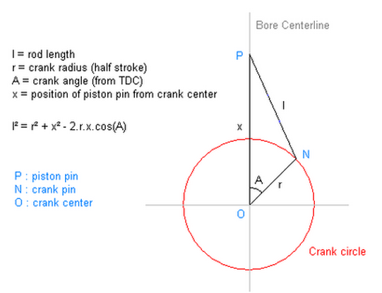
The piston position at any point in the engine’s revolution is described by the following triganometric equation (this equation is derived from the triangle shape created between the piston’s axis of motion up and down the bore, the center line running through the connecting rod between the piston pin and the rod journal, and center line running through the crankshaft between the rod journal and the center of the crankshaft)

angularity.png
 
Re: connecting rod info

You can see the rest of the piston equations (velocity and acceleration) by clicking on the link above.

So now we can calculate piston position vs crank angle for any engine, no matter what stroke it has and what rod length is there. If we combine this piston position with the exact valve timing events (intake opening and closing and exhaust opening and closing) then we can pin point exactly where the piston will be at those exact events and exactly how much pressure or vacuum has been built up when the intake and exhaust systems are connected to the cylinder (when the valves open).

This has direct and indirect effects on power delivery… first let me list all the effects, then we’ll go into some details:

Direct Effects:

1- Dynamic Compression Ratio
3- Peak compression pressure and peak combustion pressure
5- Peak engine Vacuum and peak intake velocity
6- Engine Effective Stroke

Derivative Effects:

1- Combustion Duration
2- Piston dwell time & optimal ignition timing
3- Cylinder wall friction
4- Average and peak piston velocity and safe redline

The effects listed above in bold font are effects that are modeled in our virtual dyno. The effects listed in regular type are not modeled in our virtual dyno at present but I will still discuss them here because it’s good to understand exactly what’s going on.

Direct Effects:

1- Dynamic Compression Ratio

The dynamic compression ratio is simply calculated as the ratio between the volume of air in the cylinder head plus the volume of air in the cylinder bore at the moment the intake valve closes, divided by the volume of air in the cylinder head when the piston reaches top dead center.

Holding intake valve closing (IVC) constant at 40 degrees after bottom dead center for example, an engine fitted with a longer rod (or a higher rod length to stroke ratio) will have a piston that is farther up the bore than an engine with a piston with a shorter RSR. This results in the longer rod engine having a marginally lower dynamic compression ratio (lower by 0.1 to 0.3 compression points at the extremes).

This means that running an 11.3:1 piston in a long rod engine will end up having the same dynamic compression ratio as an 11.0:1 piston in a short rod engine.

Affects similar to compression ratio (such as higher boost pressure and higher nitrous injection levels) will also follow the same trend with the longer rod engine able to take a slightly higher dose of ‘radical’ while still having the same net dynamic compression as the shorter rod engine running a ‘tamer’ superficial figure of compression, boost, or nitrous.

3- Peak compression pressure and peak combustion pressure

When the air and fuel mixture is ignited via the spark plug, the combustion of the air / fuel mixture spikes cylinder pressure to about 4.5 times the original cylinder pressure at the moment of ignition.

This is to say that igniting a mixture that is already at 10bar compression pressure results in about a 45bar final combustion pressure, but igniting a mixture that starts out at a lower 9bar compression pressure reaches a lower peak of 40.5 bar combustion pressure.

An engine with a longer rod will have a lower dynamic compression ratio compared to an identical short rod engine (as explained above) and thus the final compression pressure (which is highly related to things like detonation and head gasket holding pressure) will have a lower peak combustion pressure allowing it to tolerate higher levels of ‘radical’ in compression, leanness, boost pressure or nitrous before reaching the fuel’s octane limit or the internals’ pressure leakage limits. At the same time this means that potentially the longer rod engine can make less power (because it peaks at a lower pressure level) if not for dwell time which we’ll talk about later.

5- Peak engine Vacuum and peak intake velocity

Longer rod engines spend more duration near top dead center and bottom dead center, and less duration transitioning between the two ends of the stroke. This as discussed earlier results in a lower dynamic compression ratio (because the piston moves through the mid part of the stroke so much faster than a shorter rod engine) but results in more ‘dwell time’ near top dead center both on the power stroke and in the exhaust stroke.

In the power stroke, the piston spends a significantly longer duration near top dead center in a longer rod engine vs a shorter rod engine.

In the exhaust stroke, the piston spends a significantly longer duration near top dead center in a longer rod engine vs a shorter rod engine.

As a result, the longer rod engine holds its peak vacuum (in the intake stroke) and its peak pressure (in the exhaust stroke) for a longer duration of time (even with the same intake and exhaust cam duration as the duration I’m talking about here is controlled by the piston position inside of the overall intake and exhaust stroke durations).

This means that the longer rod engine can ‘make due’ with an undersized intake and exhaust system better than a shorter rod engine because the engine breathing happens over a longer duration in the intake and exhaust strokes and thus the peak intake and exhaust velocities are closer, in a longer rod engine, to average intake and exhaust velocities as the induction is smoothed out over a longer period requiring a slightly smaller intake and exhaust pipe.

6- Engine Effective Stroke

This is hard to visualize but easy to explain mathematically. The angle between the connecting rod and crankshaft position controls the amount of torque that is delivered from the piston (and the combustion) to the crankshaft.

Longer rods create shallower angles with respect to the crankshaft at every point in the rotation compared to shorter rod engines. This means that long rod engines deliver less torque, to the crankshaft at every point in the rotation compared to a shorter rod engine. This makes longer rod engines typically produce less torque (from the same amount of air and fuel mixture) compared to a shorter rod engine giving it a ‘shorter effective stroke’

To calculate effective stroke, re-arrange the piston position equation such that stroke can be calculated as a function of piston position, crank angle and rod length.

Taking stroke as a variable (a result) in this equation rather than a fixed dimension (an input) allows us to calculate the effective stroke of different rod length combinations and estimate the difference in torque delivery to be gained or lostby altering the RSR.

http://www.stahlheaders.com/Lit_Rod Length.htm

Summary of direct effects:

Before we even get into the derivative effects of long rod vs short rod engines, it’s already becoming clear that there is an inherent trade off between long and short rod engines…

Long rod engines can be built to more radical specs in terms of compression, air to fuel ratios, boost pressures …etc which lends them to producing higher power figures. Shorter rod engines produce more combustion and compression pressure, as well as a higher effective stroke from less radical specs effectively lending them to producing higher torque figures and wider powerbands.

Long rod engines transition faster between top and bottom dead center making more sensitive to valve timing events which is typical of ‘tuned’ motors. Shorter rod engines build vacuum and pressure over a wider range crank angles making them less sensitive to exact cam timing, but more sensitive to peak flow velocities, and undersized intake and exhaust parts which is typcial of most street engines (that respond rapidly to ported throttle bodies or oversized intakes but less favourably to wide changes in cam timing settings).

Derivative Effects:

1- Combustion Duration

The combustion duration of a mixture in an engine is a very complex issue to study. I’ve read many PHD dissertations on this topic, which goes to show you the high level of research, theory, and experimentation it takes to come up with any meaningful data on this issue.

Usually these experiments involve taking a dual plug engine (like the Golf TDI or porsche engines, or even a dual plug cylinder head conversion on a harley v-twin). Then, swapping out one of the spark plugs with a pressure transducer / infra-red camera integrated unit and measuring both the infrared image as well as the pressure readings of the combustion process inside the cylinder. Once all this data is synchronized with the crank angle, we can then read meaningful readings of combustion durations and start to vary different engine parameters to see their effect on combustion duration.

One clever article I read had fitted a 4 cylinder engine with different pistons, each cylinder had a different static compression ratio, and so the researcher was able to use the same engine (without having to tear it down and rebuild it) to research the effect of compression ratio on combustion duration.

In my research for writing the virtual dyno and the power calculator, I can summarize certain ‘trends’ that affect combustion duration as follows:

a- Combustion pressure
b- Turbulence & fractal flame-fronts
c- Distance of travel

a- Combustion pressure

The higher the combustion pressure, the more kinetic energy is stored in the compressed mixture. The higher your engine’s density ratio (boost pressure x air density) and the higher the engine’s dynamic compression ratio (static compression ratio altered by cam timing and cylinder filling) the more kinetic energy gets stored in the air fuel mixture before it is ignited. Once it is ignited this energy is released into the mixture as an accelerent of combustion.

This is why more aggressive engines (higher boost pressure, higher compression ratios, tighter cam timing with less overlap and higher cranking pressure) require less timing advance for optimum torque delivery… because all these factors shorten the combustion duration and so to optimize power delivery to always ocurr around 17* after top dead center, a faster burning mixture with shorter combustion duration will require less advance to hit that timing mark.

As I just mentioned above, combustion duration is affected by the engine’s dynamic compression ratio, which is affected by the engine’s RSR as discribed earlier and so timing advance is affected by the engine’s RSR where engines with shorter rods will have a higher dynamic compression ratio and a lower combustion duration.

The virtual dyno uses dynamic compression rather than static compression in it’s combustion duration calculations and so you will see optimal timing variations in the virtual dyno due to different rod to stroke ratios. The optimal advance though is not a straight forward endeavour as there is a balance between optimizing timing advance for peak combustion duration, and between the force delivered to the piston due to the longer rod’s longer dwell time.

So longer rod, doesn’t always mean more timing advance… it depends on the balance in the trade off between combustion duration getting longer (due to a lower compression pressure from the longer rod) with the increase in dwell time due to the longer rod angularity.

b- Turbulence & fractal flame-fronts

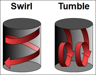
Many studies have show that flame propagation in the combustion chamber under combustion pressures and due to air turbulence (swirl and tumble) is actually faster and non linear compared to fuel being ignited in free air conditions.

swirl_and_tumble.jpg


Part of the reason for this is that the combustion process is very similar to a nuclear process where the energy released from an atomic split is enough to split the next 2 atoms, creating an nuclear chain reaction… the air fuel mixture in the combustion chamber possesses a similar amount of stored kinetic energy that gets released during combustion. The spark plug ignites the air and fuel pocket right around it. That pocket combusts and releases the fuel’s stored energy thus raising the pocket’s localized temperature in the center of the combustion chamber (for hemi heads with centrally mounted spark plugs). The edges of that air/fuel pocket now reach combustion conditions (optimal pressure and temperature) and they ignite too creating multiple pockets of elevated pressure and temperature around the original air/fuel pocket and this process continues as the combustion effect spirals outwards from the source of ignition to the rest of the combustion chamber.
If your build any BBC engine as a general rule, you can expect to see about 1-to-1.3 hp and 1.2-to-1.4 ft lbs of torque per cubic inch of displacement at the flywheel, from a properly designed engine, using higher quality components,
yes you can improve both figures but as power goes up so does component cost.
so basically theres a noticeable boost in power if you build the larger displacement engines, especially if you keep the compression ratio. up or above 9.5:1, max power will require race octane fuel and compression ratios above 12.5:1, and cams with enough lift and duration to make low speed driving in traffic miserable, and these engines will NOT be useful designs for street performance use.
 
Last edited by a moderator:
Re: connecting rod info

Engines that have high swirl and high tumble effect design built into their intake port and the top surface of the piston increase the turbulence inside the chamber which enhances the creation of these pockets and speeds up the chain reaction. Also, we know that timing advance builds with rpm up to a certain point. As the engine accelerates (trying to outrun the combustion duration) we advance timing to synchronize power delivery at 17* ATDC. However, past a certain crossover rpm (around ~3500 to ~4500 rpm in most engines) the turbulance created inside hte chamber due to the speed of the piston motion enhances the fractal effect which accelerates the combustion duration and so we no longer need to advance timing and timing levels off. This is why most engines have peak timing occurring at around ~3500 to ~4500 and then held steadily afterwards.

c- Distance of travel

As more and more fuel is burnt, the cylinder pressure keeps rising in the combustion chamber. To reach peak cylinder pressure, almost all of the air/fuel mixture has to be ignited, and to do so the fractal flame front has to travel all the way from the spark plug to the farthest point in the combustion chamber.

Engines with a larger diameter bore, and engines with a side mounted spark plug will have longer combustion durations than engines with smaller bores and engines with centrally mounted spark plugs.

In engines with a centrally mounted plug, the distance the flame front has to travel is half of the bore.
In engines with an offset mounted plug, the distance the flame front has to travel is around 2/3rd of the bore.
Engines with the plug mounted next to the exhaust ports (side mounted plugs) require more advance because the flame front has to travel the entire length of the bore.
Engines with twin-plugs have a total distance of travel of at most 1/3rd the distance of the bore so they require less advance, have a better high rpm power deliver (by about 4%) and better emissions because of a more uniform combustion across the entire air and fuel mixture in the entire surface area inside the bore.

2- Piston dwell time & optimal ignition timing

As mentioned earlier, optimizing timing advance targets delivering peak cylinder pressure at 15 degrees to 17 degrees after top dead center. However, as explained earlier, due to the angularity of the piston motion, and due to the effective stroke (which is a result of the angle and leverage the connecting rod has over the crankshaft) and due to the amount of time that the piston spends near top dead center (dwell time) being acted upon by peak cylinder pressure, we find that the total amount of force delivered from the combustion process to the rotating assembly has more to do with the sum of force applied to the piston over the duration of the expansion / power stroke .

That is to say, though we are trying to optimize timing such that peak cylinder pressure occurs ‘around’ the 17* atdc mark, the exact timing that will deliver peak torque will vary with effective stroke, and dwell time because power is delivered to the piston over a period of time, and a range of crank angles (for example 0* atdc to 71* atdc for a given rod length) and what becomes important is maximizing the total energy delivered to the crank over that duration.

The total energy delivered is the summation of the force applied over that window and the force applied is a result of the combustion chamber pressure force multiplied by the mechanical advantage that the connecting rod has on the crank lobe due to the triganometry of the assembly.

In general, the longer rod will have a higher dwell time near top dead center which will improve the energy transfer between the combustion chamber and the rotating assembly at higher rpms when the amount of time (in milliseconds) that the piston spends near top dead center gets very tight.

On the contrary, the shorter rod will be less efficient at energy transfer at higher rpms, but because it has a higher mechanical advantage (due to its longer effective stroke) will produce more lower rpm power and better torque figures.

The virtual dyno calculates power differences for different ignition timing advances and for different RSR’s by calculating this exact energy integral over the window of duration that corresponds to the ingition and camshaft timing events and uses that to judge power variations due to different RSRs and different timing settings.

3- Cylinder wall friction

The shorter the RSR the more lateral force applied on the piston as the side skirt is literally dragged into and rubbed against the inner cylinder walls. If you think about this mathematically, you can break the piston acceleration into it’s x and y (cosine and sin) components in relation to the angle between crank center-line and the connecting rod centerline.

The larger this deflection angle, the larger it’s x-component (the cosine of the relevant angle) and the larger the amount of force applied on the piston against the cylinder wall. The inverse is correct for longer rods and shallower angles.

This mechanical friction can make longer rod engines produce marginally higher power figures due to lower internal friction losses. There are also ways to reduce this friction loss on shorter rod engines such as using lighter pistons with shorter side skirts and using friction reducing coatings on the side skirts.

In general, this effect is hard to measure and not modeled in the virtual dyno. The most important thing to consider here is application design:

Engines designed for endurance racing, continuous high rpm operation, and sustained high rpm loads will always perform better with a longer RSR and a longer rod combination because of the reduced internal stress, friction, thermal buildup, and power loss on the piston skirts and the cylinder side wall.

This is why engines like Formula1 engines and 24 hour endurance racing engines will always choose a very high 2.1:1 RSR to make sure that these engines can last , easily, and happily, the entire duration of the test they will be put under.

4- Average and peak piston velocity and safe red-line

Finally, (and related to the point above) the piston velocity using the equations I’ve listed in the Wikipedia article is not constant throughout the engine revolution. Even though most designers use quick rules of thumbs for piston stroke, and average piston speed to ‘judge’ a safe redline for the engine , it is not really that accurate.

The accurate way of judging safe redline for the rotating assembly is to use the exact angularity of the internals to calculate both peak and average piston velocity. Furthermore, by taking a 3rd order derivative of the piston position equation we can produce an equation the describes the stress applied by this motion on the connecting rod (for a specific RSR). By knowing peak and average velocities and comparing them with peak and average stress applied on the connecting rod, and by comparing those figures with the metallurgic properties of the chosen connecting rod material or alloy, only then can a ‘safe red-line’ truly be set.

Yes a shorter RSR will apply more lateral load (sideways bending force) on the connecting rod and a higher average piston velocity, but these stresses and loads do not necessarily mean that the engine has to have a lower redline…. the use of a lighter and stronger connecting rod alloy (such as the Titanium connecting rods that Porsche swaps into their GT3 engines in place of the OEM rods) can allow for a ‘sub optimal’ RSR to operate at a higher redline rpm safely without worry of shattering the bottom end due to lateral stress.

The takeaway:

The RSR debate will forever live on the Internet forums as people argue right from wrong ways to setup an engine. Since I mostly focus on streetable engines and that is what most of our readers and customers are building my advice is to use the shortest possible rod that is going to be safe at your target redline rpm. Yes this will cost you some power in the higher rpm range (compared to a longer rod combo) but you can always add more power up top with a few more PSI of boost pressure or a slightly more oxygenated race fuel. However adding more torque to long rod engine, and widening your powerband (by using a smaller , faster spooling turbo or a higher compression ratio) is not always that easy to do. Smaller turbos / superchargers come with top end trade offs and changes in static compression require rebuilds and so I will always err on the shorter end of the RSR to give a more streetable car with a wider power band, so long as that RSR is still safe at my intended redline rpm.

If you’re building a track only race car…. and you want all your power near redline… and you want a more zingy rpm near the top end (which might be the case for a larger displacement motorbike engine or a track only race car, then sure maximize the rod/stroke ratio) … but for most people the wider power-band benefits of the shorter rods will be very evident in daily usage of the vehicle.

This is partly why stroker kits are very impressive on the street. They not only increase displacement by moving the crank journal upwards… they also force the use of a shorter rod and a shorter RSR which moves peak the peak torque rpm further down the rpm range, as well as boost the static and dynamic compression ratios as a result of the increased engine displacement AND the shorter RSR. For a single modification, they are pretty effective at transforming a street car into something of a torque monster and if you’re planning on staying naturally aspirated with your engine (or spraying a little bit up top) this is a definite way to widen your powerband and make a car that feels much faster and versatile compared to stock.


THINK THROUGH YOUR OPTIONS AND THE COMPLETE COMBO,
I see guys have long discussions about things like the difference in port cross sectional area or the best connecting rod length, to use, no one factor is going to make your engine totally dominate the competition, its a combo of small almost insignificant individual component choices being made and a good deal of time and effort taken during the assembly and clearancing work, that stack up to give you or prevent you from maximizing the engines performance.
you may not even think about factors like polishing crank journals, or valve train geometry or intake runner cross sectioinal area or length ,or intake runner port matching or surface finish, but the combined effects of your choices and components selected do mater!
look guys I think a good deal of this discussion is missing the point here, Ive built well over 150 engines in the last 45 years, (I lost cound decades ago)
but I can assure you that longer rods and the easily verifyable slight increase in dwell time, the longer rods produce will be totally meaningless UNLESS, you design the engine for and select components too take full advantage of the minor increase, by carefully calculating the REQUIRED compression ratio,fuel octane required,all the factors related to the cam timing,(duration,lift, LCA) you calculate and build and install, and tune the engine for , a matched exhaust header scavenging (header primairy length and diameter plus collector design) and the intake runner length and cross sectional area, to maximize the cylinder scavenging effects, plus you match the fuel/air ratio, and ignition advance curve, to maximize that longer dwell times potential advantage.
 
Last edited by a moderator:
Re: connecting rod info

I read your latest posts on Short Rod Vs Long Rods Grumpy.
I am still using DD2000.
Do You have Virtual Dyno ?
Some of those High End Engine simulatiin programs cost over $500.
I don't think it was Kurtis Levington Speaking.
Some ideas are similar.
But Kurtis has his own too.
 
Back
Top