converter to flexplate bolt holes

george88gta

Active Member
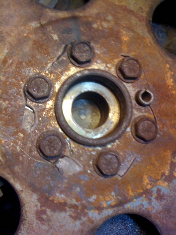
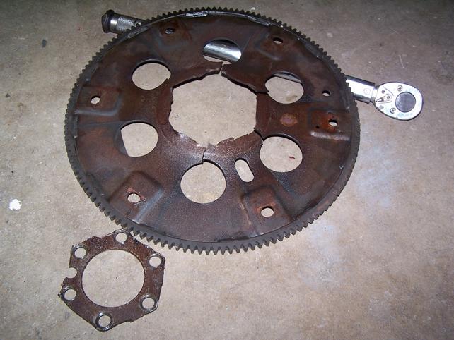
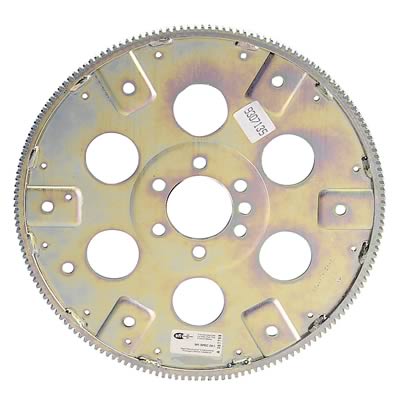
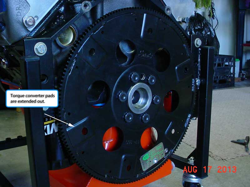
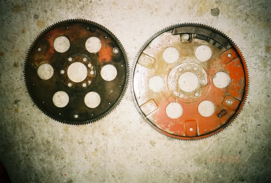
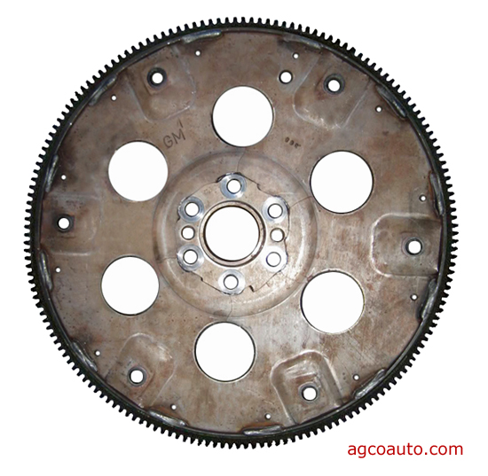
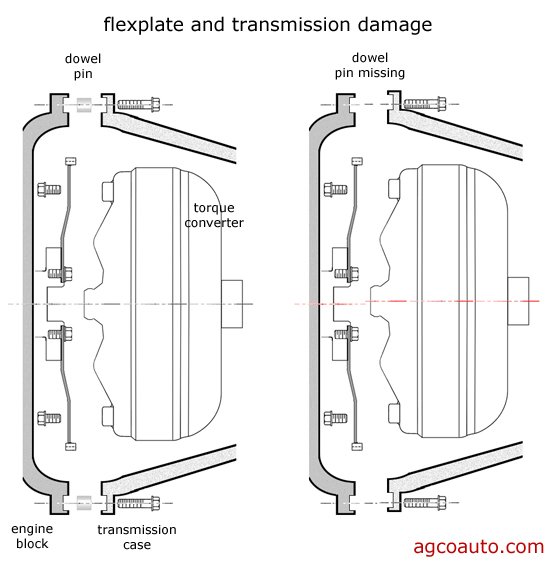
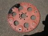
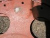
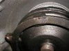
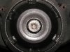
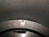
OK, was having some problems with an unusual noise in the drive train. A new GM flexplate and the new converter were installed when I installed the rebuilt 700-r4. The noise started right away after the install. Turns out that the stock flexplate ( sbc 1 piece rear main seal) was hitting the ring on the torque converter ( TCI 243107). There are 6 raised portions on the flexplate, 3 have the bolt holes and three are solid, no holes. There are wear marks on the ring where the flexplate was rubbing/vibrating. According to TCI, the flexplate should not touch the converter anyplace except where the bolts attach the flexplate to the converter. Their suggestion was to space out the flexplate, no more than 1/8". I checked the flexplate and it has one hole at 7/16" and two holes at 1/2". Doesnt seem right so I ordered a new flexplate. New one showed up today and it has one hole at 3/8" and two holes at 1/2". Spoke to Summit ( place of purchase) and they said return it and we worked for a while trying to find a flexplate with 7/16" holes for the converter bolts, no luck. Checked TCI website and they state their flexplates have 3/8" holes and can easily be drilled out to 7/16". Go figure? B&M also has 3/8" holes. Not thrilled about dropping close to $100 on a flexplate and drilling holes. So what I think would work is to drill out the 7/16" hole on the existing flexplate so that all three holes are the same diameter. That way I can bias the flexplate against the bolts before torquing. When you think about it, the engine only turns in one direction, so if I push the flexplate against the bolts, in the direction of rotation, the flexplate should remain in position. I also want to install some shims to get the flexplate away from the ring on the converter. What do you guys think, will this work?
 
tcclearance.gif


read thru these links and sub linked info


viewtopic.php?f=71&t=2400

http://reviews.ebay.com/The-Right-Stall ... 0010268586

http://prestoliteperformance.com/drivet ... lates.html

viewtopic.php?f=71&t=1715

viewtopic.php?f=71&t=435

keep in mind theres 3 and 6 bolt torque converters and several bolt pattern diameters
the spline counts and shaft diameters differ in various applications so do the required research
EXAMPLE
10.750 in.
11.500 in.

not being on site it sounds like the flex plates got the wrong side facing the crank flange OR the converters not fully seated, or possibly the bolts are to long or the oil gallery plugs in the rear of the block extend back far enough to cause a clearance problem
IF YOUR GOING TO PUT THE TIME AND EFFORT INT A DECENT ENGINE BUY AN SFI CERTIFIED FLEX-PLATE< STOCK ONES ARE SO THIN THEY CRACK CONSTANTLY IF SUBJECTED TO HIGHER STRESS
3571.jpg

brokenflexplate.jpg

OEM flex plates are far thinner and more flexible than the SFI certified flex-plates , so they are far more likely to crack and split over time,Ive had more than a few guys I know think they blew up engines who on engine dis- assembly found cracked or damaged flex plates were the cause of the engine noise


sum-g100sfi_cp.jpg


the picture above shows the crank flange side of the flex plate
 
Good info, but I am pretty sure I got those things correct. I have had the pleasure of doing this a few times and this is the first time I have had a problem. The converter doesnt have just three tabs or blocks for the mounting bolts. It has a flat ring that has three mounting holes. What is happening is the flexplate ( installed with "engine side" towards the back of the block) is hitting the flat ring in three places where there are no bolt holes. You can see shiny wear tracks on the ring and corresponding tracks on those three raised areas of the flexplate. I will try and post a pic so you can get a better idea of the setup.
 
a couple clear pictures would surely help, the flex plate is by design, bolted to both the crank flange and torque converter , and the torque converter is slid into the transmission and seated .
in a correctly clearances, drive train assembly the torque converter is fully seated in the transmission and the transmission bell housing is bolted to the engine leaving about 1/8" of forward/backward slack which is only removed by sliding the torque converter forward as its bolted to the flex plate during final assembly.
if it binds (the torque converter to the flex plate) before the bolts locking them together are in place and torqued to spec,theres usually a problem with components that are being used or the assembly process

FlexPlateInstalled_4573.jpg

400d.jpg

weights on flex plates generally face the block

http://garage.grumpysperformance.com/index.php?thr...
remember to use ARP grade 8 bolts with loc-tite in the threads RED SUGGESTED 271

https://www.summitracing.com/parts/arp-230-7305
http://www.agcoauto.com/content/news/p2_articleid/220
crft1.jpg

crft2.jpg

crft3.jpg


http://www.jegs.com/s/tech-articles/tor ... +Converter

http://auto.howstuffworks.com/auto-part ... erter2.htm

Runout - runout should be less than 0,25 mm (0,010 inch).

Balance - should be checked with the turbine in at least three positions. This insures that the converter will
not be internally out of balance. Overall balance should be held within 10 grams.

Internal Dimensional Standards:

Turbo 400 uses the Big Bolt pattern torque converter.
11.5" inches bolt circle pattern.
4L80E uses same.

4L60E, 700R4, 200R4, & Turbo 350 uses the small bolt pattern torque converter.
10.75" inch bolt circle pattern.

Fit of pilot bushing - 0,10 mm-0,20 mm (0,004 inch - 0,008 inch) typical.

index.php


crft4.jpg

crft5.jpg

transline.jpg

As misalignment increases, the flexplate flexes more. This continual flexing eventually causes the metal to fatigue and the flexplate cracks. Misalignment should be less than .008 of an inch and the less the better. When the engine and transmission are manufactured, holes are drilled for bolts to attach them to each other. These holes are larger than the attaching bolts and do not align the two components. Precision dowel pins, that fit very tightly, hold the engine and transmission in alignment.

The dowel pins must be present to align the engine and transmission


http://garage.grumpysperformance.co...rrectly-installing-bellhousings.584/#post-785
lak-15907_w

Due to manufacturers’ machining tolerances of engine blocks in relationship to dowel pin location, it is quite possible for
the crankshaft centerline and bellhousing bore to be misaligned. With the transmission installed in a misaligned condition,
several problems can occur, such as pilot bearing and main shaft bearing wear, difficulty in shifting, and in extreme cases
breakage of transmission gears and cases. While most housings will fall within the allowable limits, it is good insurance to
check for register bore runout whenever any housing or engine block is installed. Most factory service manuals will outline
the checking procedure, but will not give correctional measures necessary to ensure trouble-free standard transmission
operation, short of trial and error with switching of various O.E. housings.
NOTE: ADJUSTABLE DOWELS ARE USED TO DIAL IN BELLHOUSINGS BECAUSE THE ENGINE BLOCKS CASTED FROM THE
OEM FACTORY CAN BE OUT OF TOLERANCE. SO, YOU WILL NEED TO ALIGN ENGINE AND BELLHOUSING.
Offset dowel pins are available from Lakewood Industries to ensure correct adapter housing installation. For checking, you
will need a dial indicator (preferably
INSTRUCTIONS
1. Remove clutch assembly from flywheel and install bellhousing on engine block.
(It is easier when you leave the clutch assembly off the flywheel.)
2. Install dial indicator base on the flywheel and adjust plunger to contact the register
bore of the housing. (See photo.)
3. Rotate the flywheel and note indicator reading. Misalignment is one-half of the
indicator reading (maximum allowable is .005â€).
4. To correct off-center condition, select the offset dowel pin pair that is closest to onehalf
of the indicator reading. (i.e., if reading is .016â€, 1/2R=.008†use .007†dowels.
If reading is .024â€, 1/2R=.012†use .014†dowels).
5. Remove stock dowel pins by driving from back side or pulling with gripper
pliers.
6. Clean engine block dowel holes and coat lightly with lubricant.
7. Lubricate dowel pins and install in block. The slot in the dowel pins indicates the
direction of maximum offset. They should be installed parallel to one another,
and in pairs (both .007†or both .014†and .021â€).
8. Install and tighten bellhousing securely. Remount the dial indicator and recheck
the register bore runout (Repeat step 3).
9. To make small corrections or adjustments to the alignment, you will need to
remove the bellhousing and drive the offset dowels out of the block. Reposition
the dowels using the slot as a reference point and re-install. Re-check register
bore run-out. Repeat this procedure until the register bore is within limits

$_58.JPG


BTW the flat steel "TAN" in this picture, hard plate that is about 1/8" thick, that mounts between the flywheel and bell housing that helps protect the block from being damaged if the clutch or flywheel comes apart or loose at 6000 rpm
 
Last edited by a moderator:
I am working on it, not having any luck getting the file attached. OK, got th eproces down, but the pic is too big. Will modify and post later.
 
OK, here are the first three pics
 

Attachments

  • P1010006.JPG
    P1010006.JPG
    70.7 KB · Views: 233
  • P1010007.JPG
    P1010007.JPG
    70.1 KB · Views: 232
  • P1010008.JPG
    P1010008.JPG
    61.4 KB · Views: 231
Last two pics. As you can see, the flexplate is touching the ring on the converter and moving around/vibrating.
 

Attachments

  • P1010009.JPG
    P1010009.JPG
    56.7 KB · Views: 226
  • P1010010.JPG
    P1010010.JPG
    60 KB · Views: 227
the pictures are not detailed enough to be 100% sure but the pictures do seem to indicate the converter your currently using (you are trying to use) is not supposed to be used (you are trying to use)as a matching component with that particular flex plate as theres a clearance issue.
obviously flex plates bolt solidly to torque converters and torque converters must match both the flex-plate and transmission they are used with.
do you have the old converter used with the current flex plate and the flex plate the converter your currently trying to use was previously used with?
Id bet if you do that placing them side bye side and inspecting them carefully will show some differences critical to clearance, the flex plate should lay against the toprque converter mount flange without the bolts drawing it into place, or bending the flex plate
 
grumpyvette said:
the pictures are not detailed enough to be 100% sure but the pictures do seem to indicate the converter your currently using (you are trying to use) is not supposed to be used (you are trying to use)as a matching component with that particular flex plate as theres a clearance issue.
obviously flex plates bolt solidly to torque converters and torque converters must match both the flex-plate and transmission they are used with.
do you have the old converter used with the current flex plate and the flex plate the converter your currently trying to use was previously used with?
Id bet if you do that placing them side bye side and inspecting them carefully will show some differences critical to clearance, the flex plate should lay against the toprque converter mount flange without the bolts drawing it into place, or bending the flex plate
Unfortunately, the old parts have been recycled. The main difference I have noted is that a stock converter has three raised lugs fro the flexplate to converter bolts. The other three raised areas do not touch the converter. This converter has that ring. I spoke to TCI this morning and gave him the part numbers I am trying to use. His response was that he didnt see why they wont work. I sent him a set of pics so he could see the interference. I reread the install instructions and they seem to be a bit generic and there is no mention of a specific flexplate requirement. There is also no mention of a specific flexplate in the info section for this converter. I will post their response.
 
Received a response from TCI. Their position is that the converter bolts came loose or were not torqued down properly. They also stated that it is normal for the raised portions on the flexplate to contact the ring. Recommendation is to get new converter bolts and do not bother to drill out the one 7/16" hole to match the other two holes ( 1/2"). Spacing out the flexplate , from the converter, isnt necessary(I can always try that later on). So that is what I will try. Off to a speed shop tomorrow to obtain some ARP converter bolts and then continue with the engine install on Monday. I will post when I get this together, hopefully without the noise.
 
george88gta said:
Received a response from TCI. Their position is that the converter bolts came loose or were not torqued down properly. They also stated that it is normal for the raised portions on the flexplate to contact the ring. Recommendation is to get new converter bolts and do not bother to drill out the one 7/16" hole to match the other two holes ( 1/2"). Spacing out the flexplate , from the converter, isn't necessary(I can always try that later on). So that is what I will try. Off to a speed shop tomorrow to obtain some ARP converter bolts and then continue with the engine install on Monday. I will post when I get this together, hopefully without the noise.
I would still drill the holes to the 1/2", that way you would know it's not going to effect the balance. Also if you bought only 7/16" ARP bolts then there will be extra clearance on two holes, therefore only one bolt hole is supporting all the torque until it makes the one hole in the flexplate bigger and the 2 other bolts make contact...... OR you will have to buy two sets of bolts and cost you twice as much. Just my 2 cents worth ;)
 
I spoke with an engine shop a while back and he told me that removing that small amount of material really wouldnt effect balance. What I like about drilling the hole out to 1/2" is that then I can bias the flexplate against the bolts , in the direction of rotation, and that should help keep things in spec. At any rate, new bolts are in order and maybe some lubrication on the non-bolted mating surfaces.
 
george88gta said:
I spoke with an engine shop a while back and he told me that removing that small amount of material really wouldnt effect balance. What I like about drilling the hole out to 1/2" is that then I can bias the flexplate against the bolts , in the direction of rotation, and that should help keep things in spec. At any rate, new bolts are in order and maybe some lubrication on the non-bolted mating surfaces.
You did check and they should know, so sounds like there will be no problem......good luck!
 
Update. I redrilled the new flexplate holes to 1/2 inch and installed the parts. So far all is well, I didnt have to bias the torque converter to the flexplate, the hole celarance was tight. No strange noises and no wierd shifting. Hope it stays this way. :D
 
Back
Top