Dan From Sault Ste Marie Ontario

Watched engine masters yesterday about that. First I heard of such. It made a very small change
I was aware of the change, but didn't want to try and keep track of it every time I messed with the
plug wires. And the poor guy that got engine down the road if I forgot to tell him, he would really be
screwed-up.
 
According to the link below the firing order of the truck engines (and all GenIII/IV LS Engines) is 1 – 8 – 7 – 2 – 6 – 5 – 4 – 3 so the crane cam shouldn't be an issue.
Yeap, I assumed something and it bit me. Learned something new today!

Checked my email this morning and Larry responded last night about 8 pm. At first glance I should
be able to use the Summit 8707 cam for the first sim, but the other two might required another
email exchange.
 
Thanks Rick. I have called the summit tech line and they are going to request the cam profile for the 8720. I will dig around for the crane cam as well.
Maybe we will get lucky.
 
You should review the attached PDF report, it will have all the numbers I have entered into
Dynomation. If there is a problem we need to correct it now before we get down the road to
Sim06 and find out we have been comparing everything to a Sim that is invalid.

The Summit 8707 cam is asymmetrical on the intake lobe only and it's just 1°. Larry's response to this cam is below the graph.

I would also like to verify that 792 CFM induction number is at 1.5 inHg.

I sent Larry another email and I am waiting his 2nd response concerning the Crane cam and it's asymmetrical lobes.

Sim01_Sum8707.jpg

Larry's email response below:

I had a look at the timing specs for the Summit cam SUM-8707 you provided.

The cam does have a slightly non-symmetrical lobes. If you calc the centerlines manually, you get:

111 IC_006 ((26 + 68 + 180) / 2 ) - 26

115 EC_006 ((79 + 29 + 180) / 2 ) - 29

110 IC_050

116 IC_050

But there is more to consider. If you calc the Intake Duration at 0.006, you get 26 + 68 + 180 = 274. It’s published
on the Cam Card as 275.

These discrepancies, I believe, are due to the fact that the actual Intake timing values are probably 26.5 and 68.8
and they did not want to use fractional values on the cam card.

All in all, the 0.5 degree differences won’t amount to much in the simulation.

.
 

Attachments

  • Sim01_Sum8707Cam.pdf
    255.2 KB · Views: 1
index.php

obviously you will select the cam based on the trucks intended use and if its an auto transmission,
youll need to consider the converter stall limitations,
power brakes injector flow rates etc, and rear gear ratio
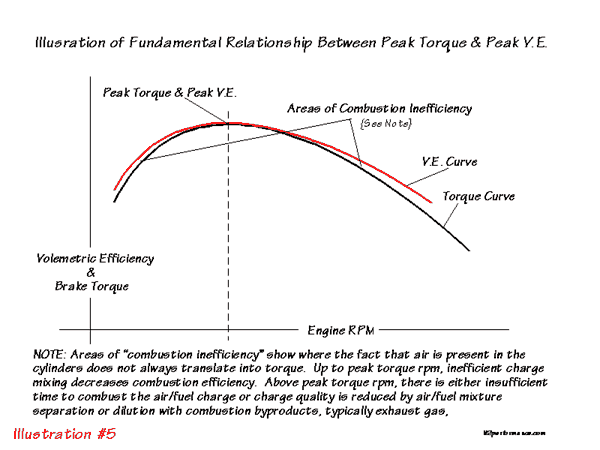
ANYTIME YOU SEE A GRAPH LIKE THIS
where the torque peaks about 1200rpm-1500 rpm lower,
than the hp peaks
and
the hp peaks lower than the torque ,

its a good indicator that you can step up the port size and cam duration,\
to potentially increasing power, or at least it may be an option,
so if you already installed that cam,
Id at least go with a set of higher ratio rockers to maximize port flow rates,
or if you have not purchased the cam, at least consider adding at least 5-8 degrees more duration,
it should make noticeably more power if the head flow and exhaust flow are not maxed out.

perhaps RICK could graph this and compare the result:D
https://www.summitracing.com/parts/sum-8708
volumetric.gif
 
Last edited:
I assume everything looks OK with the report numbers.

Larry sent me a file with a Crower Cam that he considers to be very close to the Crane 1449121,
this is what you see on the graph below as Sim03.

Sim01_Sim02_Sim03_Compare.jpg

Will work on the Summit 8708 cam suggested by Grumpy.
.
 
Summit 8708 Camshaft in Sim04.

This cam is similar to the Summit 8707 in that it is Asymmetrical. So the timing numbers are
off by about 1.5° in some areas.

HR_Summit8708_Tab-VET.jpg

Sim01_Sim02_Sim03_Sim04_Compare.jpg
.
 
Last edited:
I would also like to verify that 792 CFM induction number is at 1.5 inHg.
The data I found stated that the testing was done at 28" H20 or 28in H20= 2.060 in Hg

I also noticed that the combustion volume you listed was 84.3cc while mine was calculated at 84.0cc (not sure if this is big enough to make a difference)

I also saw that you listed the intake running diameter as 1.890 inches which matches the intake valve size, but the exhaust running diameter is listed as 1.500 when the exhaust valve diameter is 1.550 (not sure if this is a big difference though).

its a good indicator that you can step up the port size and cam duration
I believe there is a lot of room for improvement on these heads and plan on porting and polishing them. The flow numbers I had were for stock un-ported/un-polished heads. Although I am not sure how much improvement I can expect (especially as this will be my first set of heads I port and polish).
 
The data I found stated that the testing was done at 28" H20 or 28in H20= 2.060 in Hg
Dynomation only accepts 1.5 or 3.0 inHg, since that is how 2 bl and 4 bl carburetors are rated.
Lets keep it set to 1.5 inHg since that is closest.

Simulation programs are better at spotting trends and not so much at predicting absolute
numbers. Another words, better at comparing engines.

I also noticed that the combustion volume you listed was 84.3cc while mine was calculated at 84.0cc (not sure if this is big enough to make a difference)
It's not going to make much difference, but just to prove it to myself I made the necessary changes. Then
I compared to two graphs and they were essentially on top of each other, so maybe 1 or 2 HP difference.

I also saw that you listed the intake running diameter as 1.890 inches which matches the intake valve size, but the exhaust running diameter is listed as 1.500 when the exhaust valve diameter is 1.550
OK, I looked over the settings in Dynomation and I don't have a way to control that. Evidently it was telling
you the assumptions that it was making. But that was good catch, you are paying attention !!! :)

I believe there is a lot of room for improvement on these heads and plan on porting and polishing them. The flow numbers I had were for stock un-ported/un-polished heads. Although I am not sure how much improvement I can expect (especially as this will be my first set of heads I port and polish).
@Grumpy may have an opinion on this, let see what he has to say.

You say Port & Polish .... what exactly do you have planned ?

I went through the report line by line and the numbers look good (see post above for what I did notice). I am not sure if those things are a big deal or not.
Thanks for doing that, not everyone goes to the trouble ! It shows your attention to details and an interest
in getting this engine built correctly.
 
You say Port & Polish .... what exactly do you have planned ?
Currently I am still diving deep into the information available on porting LS heads. So I am all ears if those who have done this before want to lend me their advice.

As of now, I plan on:

INTAKE: grinding out the swirl ramps, turning the valve guide boss into an air foil shape, grinding out the rocker stud bump, and smoothing out any bumps near the valve seat. I will also use the sanding rolls to remove the casting flash. I do NOT plan on touching the short turn radius, or trying to enlarge the ports by opening up the floors and walls.

EXHAUST: Turning the valve guide boss into an air foil shape, raising the exhaust port roof to match the header gasket and blending to the original port size, and then I will polish the exhaust port as shiny and smooth as I can get it.

BOWL: I will clean up the bowls and polish them removing any sharp edges. I will try to remove as little material as possible to keep my combustion chamber size where it is. (I will mill them down to get compression where it needs to be if necessary).

Here are some LS head porting links I have found:

https://ls1tech.com/forums/generati...759-diy-ls1-head-porting-home-can-help-4.html

https://ls1tech.com/forums/generation-iii-internal-engine/1522294-pics-my-diy-ported-heads.html

https://ls1tech.com/forums/generati...project-5-3-heads-lots-o-pics-56k-beware.html

There are also quite a few other good videos on this guys channel

If anyone reading has other LS head porting experience or suggestions (especially for 862/706 heads) let me know!
 
I really appreciate all the help that Rick has given me. I also think it is awesome that the trend Grumpy predicted is what we saw with the 8707 to 8708 camshaft. This curve just isn't what I was looking for though, so I am going to re-evaluate the build and come up with another iteration.
 
Rick is always willing to help. I just got home from his house where we rebuilt my new to me Weaver 4 ton floor jack. I want to thank him publicly for all his help and guidance. Thank you Rick.
 
Both you guys are welcome, I do it because I enjoy helping !

Daniel,
Now that we have the engine built in Dynomation, it's easy to try different camshafts. So don't hesitate
to ask for a bunch more camshaft changes.
 
Thanks Rick.
As I keep looking into this I am finding that the heads (due to the small cross sectional area and smaller valve 1.890/1.550) are not optimized for the engine. I can change cams, and am looking at cams with numbers like the summit 8702 https://static.summitracing.com/global/images/chartsguides/s/sum-8702.pdf, but to swap to this cam I would change heads for flow, pistons for compression and possibly the intake as well.
How much work is it to change all of those parameters?
Is it worth running a sim with just the cam to see if it will increase torque production beyond the 4000 rpm band?
Basically I love the torque curve under 4000 rpm, but I just wish it held out longer until about 5000 rpm.
 
that cam looks like a good choice, just be very sure you check all clearances
 
Back
Top