my wifes got a mercury that has had an intermittent issue with both the head lights going out at times while driving at night,
I found the problem to be a defective relay within the lighting control module. My local mercury dealer will replace the module for about $900.00, the price of the lighting modual is $495, the cost is to first diagnose then replace, then program the module and install it. The defective component part can be obtained from Mouser Electronics online for under $6.00. If you can solder it is a simple task, just locate the module which is found mounted under the lower dashboard to the passenger side of the steering column. Three plugs must be removed after you slide it out of the mounting tray. Open it up and you find four identical relays. The headlight relay is on the side opposite the long heat sink and nearest the vehicle connectors. OEM p/n NEC EQ1-11111S. There is another post here with great photos which guided me. Look for discoloration on the PC board from the heat generated by the arcing contacts.
Good luck.
http://garage.grumpysperformance.com/index.php?threads/digital-dash-swap-questions.3399/#post-8970
http://www.how-to-build-hotrods.com/fuse-panel.html
http://www.delcity.net/store/Sealed-Mini-Fuse-Panels/p_803796
http://www.rbracing-rsr.com/wiring_ecu.html
http://www.hotrod.com/how-to/engine/1408-how-to-wire-your-own-race-car/
http://www.onallcylinders.com/2013/12/05/wiring-101-basic-tips-tricks-tools-wiring-vehicle/
http://www.themotorbookstore.com/automotive-electrical.html
http://garage.grumpysperformance.co...arting-the-cars-partially-dead-battery.15608/
http://garage.grumpysperformance.co...rvette-after-battery-failed.10291/#post-41710
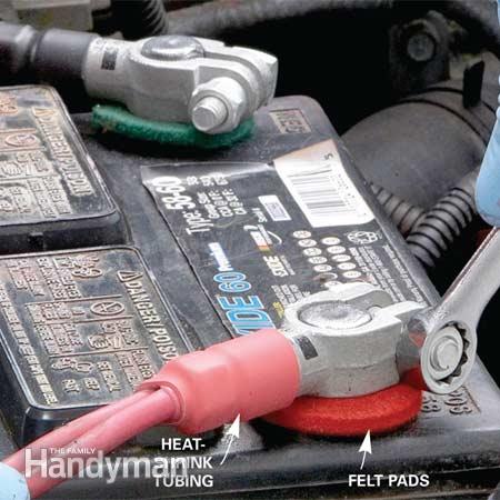
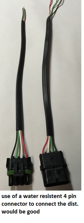
use of and taking the time and effort, when building or repairing the wiring on any custom car, to install a $5 -$7, UNIQUE for each electrical component , quick connect indexed water resistant screw-up proof, male/female connector combo, that allow's you too quickly connector remove a distributor or other component from the cars wire harness and re-install it with little chance of screwing up the electrical connections is almost always a good idea
https://www.jegs.com/i/JEGS/555/10308/10002/-1
ford remote starter relays can be used in many higher amp fan circuits
Mustang Starter Solenoid 1965-1973
TYPICAL ACCESSORY CURRENT DRAW (AMPS)
Lights
Headlights (high beam)40
Headlights (low beam) 10-22
Tail Lights 8
Safety
Emergency brake light 4
Emergency flasher 15
Turn signals 10-15
Windshield wipers 6-20
Horn 15
Brake lights 15-20
Running lights 8
Ignition
Winter starting 225-500
Summer starting 100-400
Approx. Avg. 300
Courtesy
Cigarette lighter 15-20
Interior lights 10-15
Instrument panel lights 4
Entertainment
Radio 10
Stereo Tape 10
Electric antenna 20
Comfort
Air conditioner 10
Heater 20-30
Defroster 15-30
Electric seat 20
Electric windows 20-30
TYPICAL ACCESSORY CURRENT DRAW (AMPS)
Typical Current Loads for Automotive Systems, Lighting and Accessories:
Engine Idling (no lights or accessories on) - 35 to 50 amps. This will vary depending on the number of cylinders (more cylinders draw more power for the fuel injectors and coils), the type of fuel injectors (some draw higher amp loads than others), the type of ignition system (single coil or multi-coil), the amp draw of the PCM, and the fuel pump (the amp draw will be higher with higher pressure systems).
Engine Off (nothing on) - 40 to 50 milliamps (power drain by modules in sleep mode, antitheft system and keyless entry)
Ignition Coil (single oil-filled coil older vehicle) - 3 to 4 amps.
Ignition Coil (single DIS coil newer vehicle) - 5 to 6 amps.
Ignition Coil (coil-on-plug) - 6 amps per coil.
Ignition System (primary circuit) - 6 to 20 amps.
Fuel Injectors - 4 to 6 amps peak, 1 amp hold
Electric Fuel Pump (depends on pressure and flow) - 4 to 12 amps
Electric Cooling Fan (depends on size) - 6 to 30 amps
Headlights (halogen low beam) - 8 to 9 amps per pair
Headlights (halogen high beam) - 9 to 10 amps per pair
Headlights (halogen high and low beams combined) - 17 to 19 amps
Headlights (High Energy Discharge) - 12 to 14 amps during initial start, 7 to 8 amps once bulbs are hot
Headlights (LED) - 0.6 to 1 amps per bulb
Small bulbs (incandescent) - 0.3 to 0.4 amps per bulb
Small bulbs (LED) - 0.04 to 0.06 amps per bulb
Starter Motor - 200 to 350 amps
500 Watt Sound System - 42 amps
Electric Rear Window Defroster - 10 to 20 amps
Windshield wipers - 2 to 10 amps depending on load
Heated Seats - 3 to 4 amps per seat
Power Windows - 3 amps
Electric Power Steering - 2 to 40 amps depending on load
Air Conditioner Compressor Clutch - 2.5 to 5 amps
Heater A/C blower motor (depends on load, size and speed setting) - 2 to 30 amps
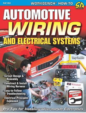
http://www.amazon.com/Automotive-Wi...automotive+electrical+books#reader_1932494871
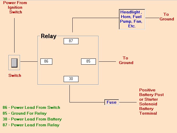
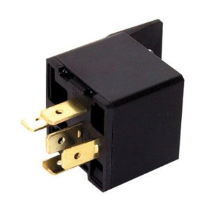
relay
http://www.amazon.com/Absolute-RLS125-1 ... 436&sr=1-1
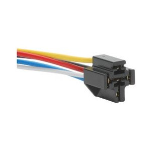
socket
http://www.amazon.com/12-VDC-5-PIN-RELA ... gy_e_img_b
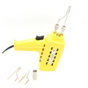
solder gun
http://www.amazon.com/Wall-Lenk-WG991KC ... -2-catcorr
BETTER GUN
https://www.amazon.com/Weller-D650-...rd_wg=GCLiY&psc=1&refRID=E9E289PYPF1G6T7YT7XV
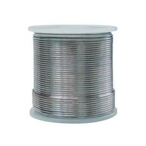
solder
http://www.amazon.com/Mobilespec-Rosin- ... 44&sr=1-10
flux
http://www.amazon.com/Dorman-9-1309-Pas ... 899&sr=1-1
http://www.crownvic.net/ubbthreads/ubbt ... er=2159211
http://www.crownvic.net/ubbthreads/ubbt ... er=2159211
http://garage.grumpysperformance.co...urrent-flow-grounds-and-more.3504/#post-33365
BTW I followed the directions (LINK above) to fix my wifes mercury light problem and the parts cost me $14 on amazon.com and it took about 1hour vs the $900 the dealership wanted for the parts and labor
http://www.deutschconnector.com/
http://www.leashelectronics.com/
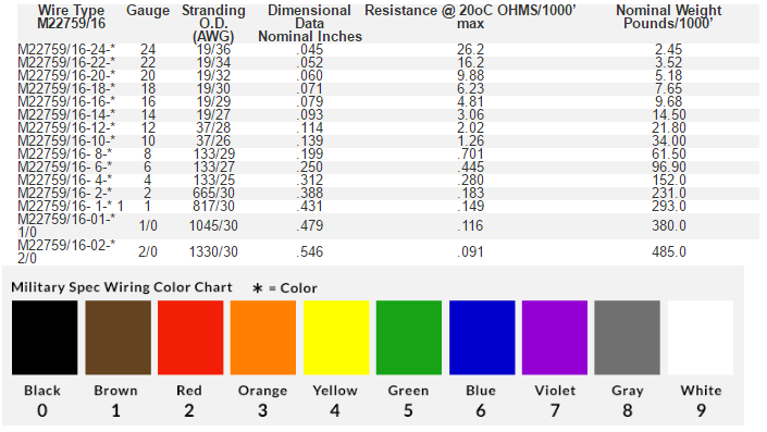
M22759/16 Tefzel Wire
Insulation: Ethylene-Tetrafluoroethylene (ETFE)
Tin Plated Copper Conductor
Voltage Rating:
600 Volts
Temperature: 150°C
Standard wall ethylene-tetrafluoroehtylene (ETFE) insulation ( also known as Tefzel ) designed for aerospace applications where weight, dimensional tolerance, and mechanical durability are required. This wire exhibits high chemical and radiation resistance. The tin plated copper conductor offers a cost savings over the silver plated high strength copper alloy which is available on M22759/17.
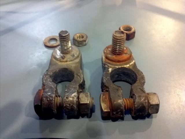
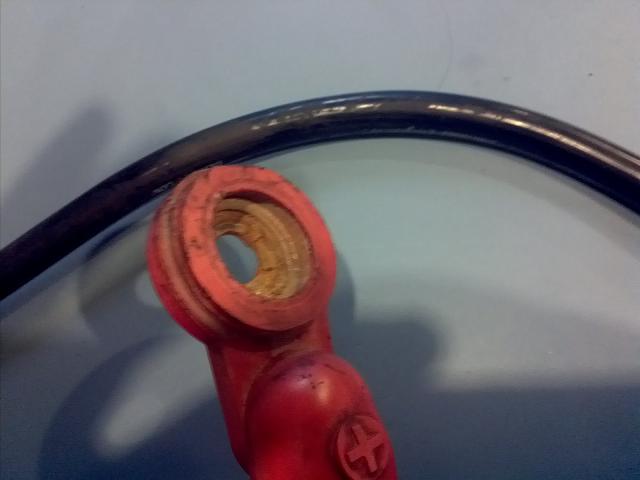
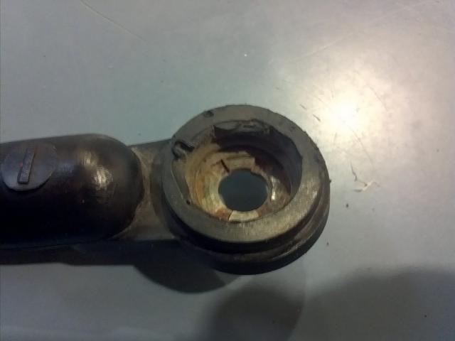
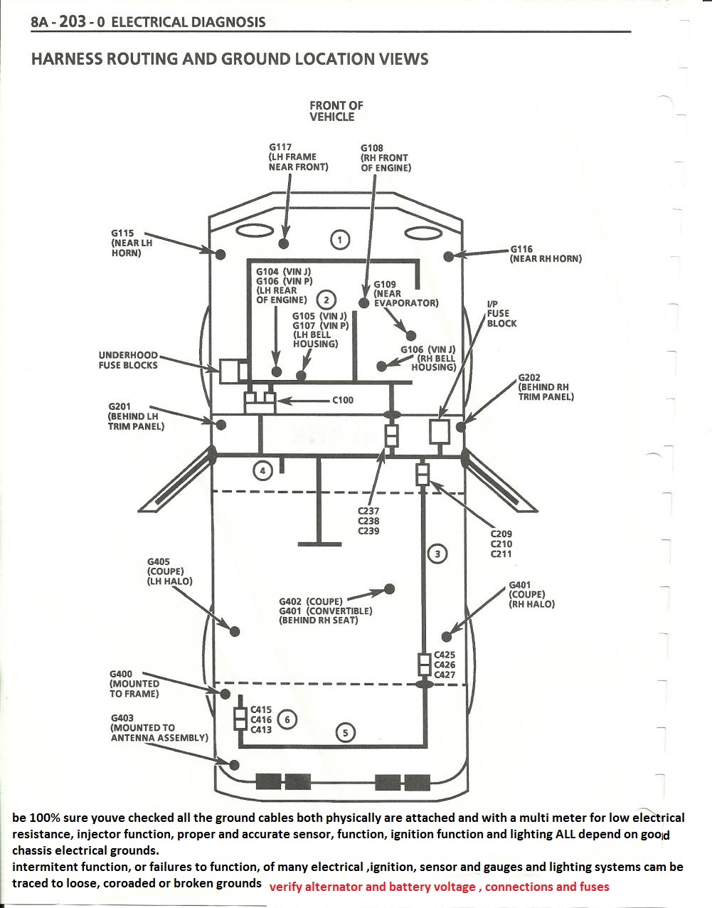
btw the most common electrically related problem I see on a consistent basis is corroded or badly rusted or defective battery connections and grounds so before you go crazy its a good idea to replace those as a first step in any electrical problem diagnoses
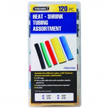
http://www.harborfreight.com/120-piece- ... 67530.html
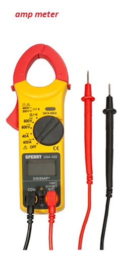
yes they always seem to assume that everyone has unlimited access to both tools and every possible part and location on a corvette, youll need a good multi meter AND an assortment of test leads and it helps a great deal to have visited a salvage yard and grabbed a bunch of electrical connectors to use when making test lead connections, or they can be purchased as replacement parts
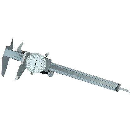
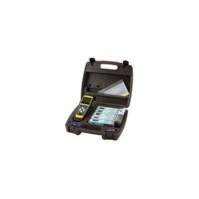
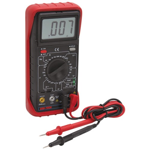
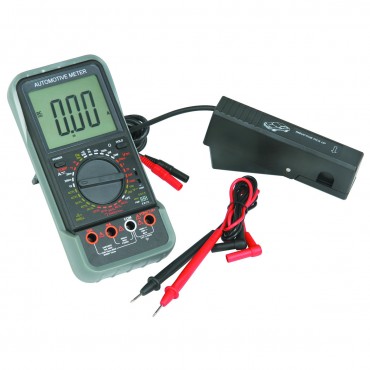
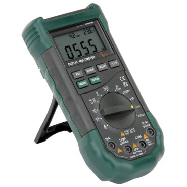
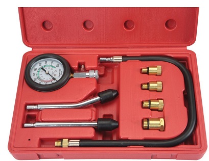
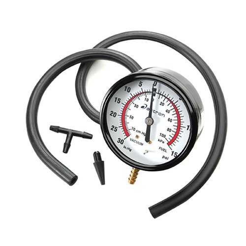
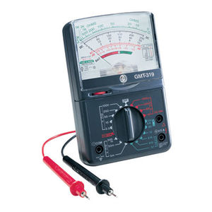
having a few basic meters,gauges etc. helps
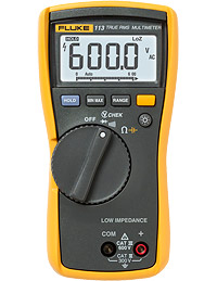
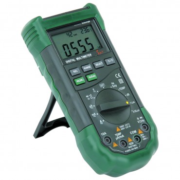
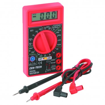
MULTI METER
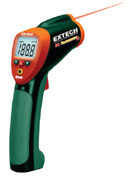
INFRARED TEMP GUN
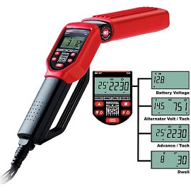
TIMING LIGHT
COMPRESSION GAUGE
PRESSURE/VACUUM GAUGE
every mechanic needs an ANALOG multi meter for testing capacitors with a micro farad scale, AND a DIGITAL MULTI METER
http://forum.grumpysperformance.com/viewtopic.php?f=36&t=63&p=3403&hilit=vats#p3403
use of a shop manual and multi meter can be very helpful
the search feature, is always an option here, on this site, but to save time , look at the sub links in these threads, to find sources for replacement electrical connectors, and NAPA can frequently ORDER replacement connectors for repairs at about 3- 5 times the cost youll find them at else ware, but at times getting the part the next day beats waiting a week so the price may be justified. if its a connector thats likely to break frequently buy extras, and have them handy
viewtopic.php?f=36&t=3105&p=8272&hilit=connectors+pigtails#p8272
viewtopic.php?f=32&t=168&p=41767&hilit=connectors+pigtails#p41767
viewtopic.php?f=80&t=728&p=43477&hilit=electrical+connector#p43477
http://www.harborfreight.com/5-in-1-dig ... 98674.html
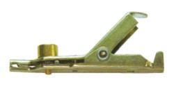
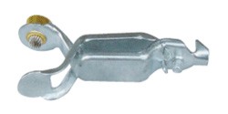
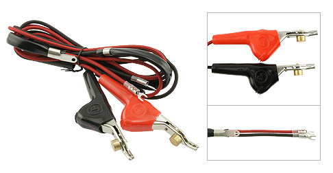
having a wide assortment of different multi meter test leads available is a huge benefit while testing
the clip test leads that test thru a wires insulation without much damage are a big help
NOW IF YOURE JUST LOOKING FOR A INTERMITTENT PROBLEM WITH YOUR CORVETTE THIS MAY HELP
theres several obvious and a couple less obvious things to check,start by pulling trouble codes, checking for loose electrical connections and vacuum lines.
Id start with checking the injector resistance and verify pulse with NOID LIGHTS , check the fuel rail pressure and ignition timing and advance, , ALL SHOULD BE OBVIOUS PLACES THAT COULD CAUSE PROBLEMS , loose electrical connections and grounds are always suspect, the most common cause I find for the lag,well (after verifying its not injector or fuel pressure or OXYGEN SENSOR RELATED or ignition , or knock sensor related,problem )obviously those should be checked , is problems related too the manifold and engine and air heat sensors, those sensors seem to be able to function well enough not to throw trouble codes but not always well enough to allow the engine to run perfectly
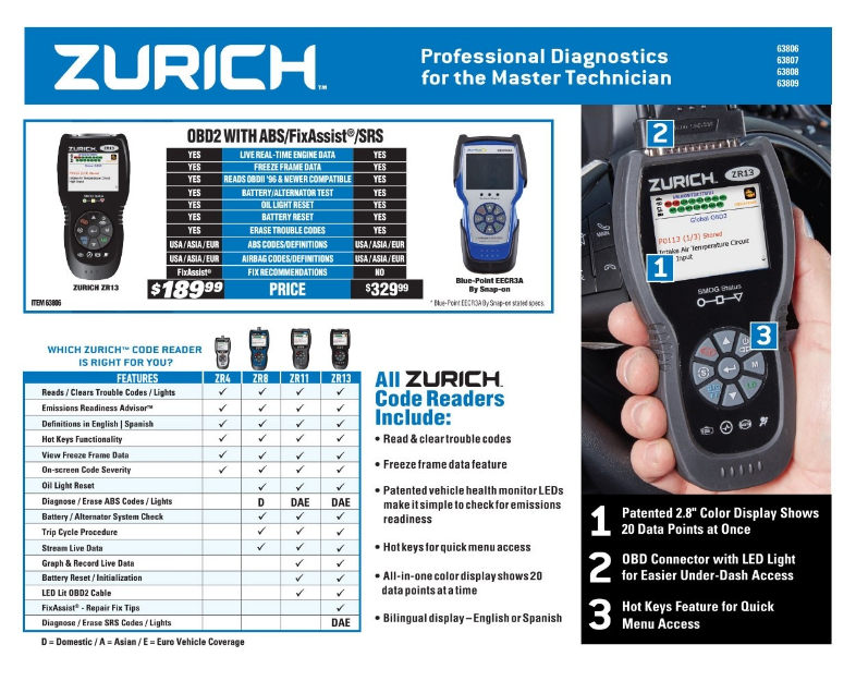
this looks interesting with a discount coupon its discounted to about $169.99 until 4/30/18 plus $49.99 for a two year 100% warranty
http://garage.grumpysperformance.co...pro-scanner-harbor-freight-zurich-zr13.14833/
if you purchase a ZR13 auto code scanner, from HF,
you need this info
DOWN-LOAD AND PRINT IT OUT!
https://manuals.harborfreight.com/manuals/63000-63999/Q63806.pdf
https://manuals.harborfreight.com/manuals/63000-63999/63806.pdf
https://www.harborfreight.com/catalogsearch/result/index/?dir=asc&order=EAScore,f,EAFeatured+Weight,f,Sale+Rank,f&q=zr13
Ive also been playing with a friends scanner, for OBDII (1996 and newer cars)
it works with a down loaded app on your blue tooth comparable I-phone/I-pad without a connecting cord, it seems to work reasonably well
and its only $100.00 so its priced lower mid range
https://www.walmart.com/ip/BlueDriv...MI78GE4Pau3wIVRNbACh1niQWAEAYYAiABEgLg9_D_BwE
https://www.amazon.com/Bluetooth-Ad...t=&hvlocphy=9012039&hvtargid=pla-761431569272
related info
http://www.agcoauto.com/content/news/p2_articleid/157
http://www.fluke.com/fluke/uses/com...articlecategories/electrical/diagnosevoltdrop
http://www.aa1car.com/library/tselec.htm
http://www.hotrod.com/how-to/interior-electrical/116-0507-top-10-electrical-fixes/
now one of the lesser known causes of u-joint failure , is the result of missing or high electrical resistance engine electrical grounds,
you should always ground the engine and transmission to the chassis ground in at least two places.
its not all that uncommon for a badly grounded engine to need the u-joints , radiators , pilot bearings and starters replaced on a much higher frequency,
simply because electricity will take the path of least resistance, to flow and if the engines rubber transmission and motor mounts,
and rubber exhaust system hangers make the drive shaft a partial path for the engines electrical ground, that current can and will eventually cause damage to the u-joints.
"from ARCOAUTO
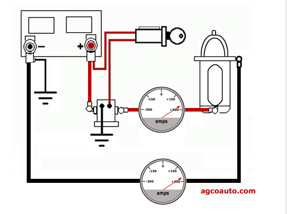
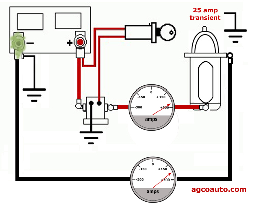
If the cables, grounds and terminals work as designed, current flow is not a problem. When cranking the vehicle, we turn the key and electricity flows from the battery to the starter motor, through a solenoid. We need the solenoid, because the key switch cannot conduct the high amperage needed to operate the starter. The solenoid acts like a heavy-duty relay. It allows the light-duty key switch to control the high-amperage starter motor.
After flowing through the starter, the current returns to the battery through the engine block. They connect the engine to the electrical system with a heavy cable, attached to the negative battery terminal. This completes the circuit. The starter uses 275 amps to turn and the same current returns to the battery. Current flow on both cables equals 275 amps. The current returning to the battery equals that leaving it.
Problems occur when corrosion and loose connections cause high resistance. The ground cable may only be able to flow 250 amps. If the starter pulls 275 amps, twenty-five amps will find another path to the negative terminal. This is known as transient current flow; electricity taking a path, other than that designed, to return to the battery. The end result can be considerable damage to seemingly unrelated components.
Transmission and suspension components are not designed to flow electricity. As the current flows through them, metal can be transferred from on part to another. This is similar to the electroplating process. In time the parts are destroyed and there may be a major failure.
Keeping all battery terminals clean, tight and with proper connections can help prevent transient current flow.
ost folks have never heard of a transient current flow. Transient current flow can cause thousands in damage to a vehicles. Normally there are very few outward signs until it is too late. Fortunately it can also be detected and prevented, with a few simple steps.
When there is an electrical load in our vehicle, current flows from the battery to the load. A positive current leaves the battery and travels through wires to the accessory. The same amount of current must also return to negative side through a ground. The ground may be provided by a wire or sometimes the vehicle body. The body is electrically attached to the negative terminal.
The current flow leaving and returning to the battery has to be equal
CORRECT GROUNDS
LOOSE CORROADED GROUNDS
Battery terminal corrosion is a symptom of another problem
A few symptoms of transient current flow
- Early or repeat rack and pinion failure
- Flickering or pulsing headlamps
- Unexplained or repeat electrical failures "
THESE THREADS AND SUB LINKS MAY HELP
grab a multi meter and check the sensor resistance and for a good electrical connection
viewtopic.php?f=80&t=728&p=43477&hilit=camaro+sensors#p43477
viewtopic.php?f=50&t=9478&p=34812&hilit=grounds#p34812
viewtopic.php?f=32&t=9778&p=36976&hilit=camaro+sensors#p36976
viewtopic.php?f=32&t=2697
viewtopic.php?f=32&t=596
viewtopic.php?f=32&t=10349
viewtopic.php?f=32&t=2697&p=29270&hilit=vacuum+lines#p29270
viewtopic.php?f=44&t=758&p=1087&hilit=opti+crap#p1087
viewtopic.php?f=36&t=520&p=645&hilit=vats+resistor#p645
viewtopic.php?f=32&t=1401
Re: C4 sensor and relay/switch locations and info
http://www.corvettebuyers.com/c4vettes/ ... mation.htm
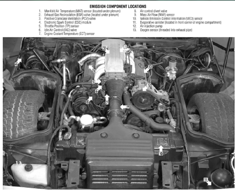
EMISSION COMPONENT LOCATIONS
Measured Value
Engine Coolant Temperature Sensor. 185 Ohms @ 210F, 3400 Ohms @ 68F, 7,500 Ohms @ 39 F.
Engine Oil Temperature Sensor. 185 Ohms @ 210 F, 3400 Ohms @ 68 F, 7,500 Ohms @39 F.
Oil Pressure Sender/Switch. 1 Ohms @ 0 PSI, 43 Ohms @ 30 PSI, 86 Ohms @ 60 PSI.
Fuel Quantity Sender. 0 Ohms @ Empty, 45 Ohms @ 1/2 Full, 90 Ohms @ Full.
MAT (Manifold Absolute Temperature Sensor). 185 Ohms @ 210 F, 3400 Ohms @ 70 F, 15,000 Ohms @ 40 F.
Outside Temperature Sensor. 4400 Ohms @ 60 F, 2200 Ohms @ 85 F.
In Car Temp Temperature Sensor. 4400 Ohms @ 60 F, 2200 Ohms @ 85 F.
MAF (Mass Air Flow) Sensor. .4 Volts @ idle, 5 Volts @ Full Throttle.
Oxygen (O2) Sensor. .1 Volt Lean Mixture, .9 Volt Rich Mixture.
TPS (Throttle Position Sensor). .54 Volts Idle, ~ 5 Volts Full Throttle.
Sensor Locations
Sensor
Location
Engine Coolant Temperature Sensor. Front of engine, below Throttle Body.
Engine Oil Temperature Sensor. Left rear of engine, just above the oil filter.
Oil Pressure Sender/Switch. Top, left hand rear of engine.
Fuel Quantity Sender. Top of fuel tank, beneath filler pipe escutcheon panel.
MAT (Manifold Absolute Temperature Sensor). Underside of manifold air plenum at rear.
Outside Temperature Sensor. Right side of engine, top right corner of radiator.
In Car Temp Temperature Sensor. Coupe: above left seat near interior courtesy light, Convertible: center of cargo compartment lid.
MAF (Mass Air Flow) Sensor. Front of engine ahead of throttle body.
Oxygen (O2) Sensor. Left side of engine, in exhaust pipe.
TPS (Throttle Position Sensor). Right side of throttle body at the front.


 Please vote!!!