1963-1979 Differential Rebuild
By Jeremy Smith
If you want the absolute best job out there, you can do it a few ways. One, you can send your diff to Mike Dyer (tracdogg2) or Gary Ramadei (GTR1999), OR you can build it yourself to their standards – which will probably cost you a little more because you have to buy the correct tools, pay for your mistakes (which will happen, trust me on this one), and build yourself custom tools…but you will have them for the rest of your life (and you can say that you built it!). I suggest you get in contact with them whether you plan on rebuilding your differential yourself or are having them rebuild it for you. I for one will no longer buy diff parts without first contacting Gary or Mike – they are straight up and only sell quality stuff.
I am writing this rebuild paper out of my own will. I do not intend to take any business away from the Corvette vendors out there – I am just a regular guy who likes to build stuff, that’s it. I’m only 18, and don’t even have the abilities to start a differential business. Sure I’ll help guys rebuild their diff and answer questions, but I’m not taking in work to compete with the vendors. I don’t have the time, money or even the facilities for that matter. This paper is designed to assist those who want to take on the task of rebuilding a diff by themselves.
If you have any doubt about your abilities to rebuild a diff, then send it out to get rebuilt by a professional. I am not liable for any of the work you do.
First Inspection/Disassembly of Unit
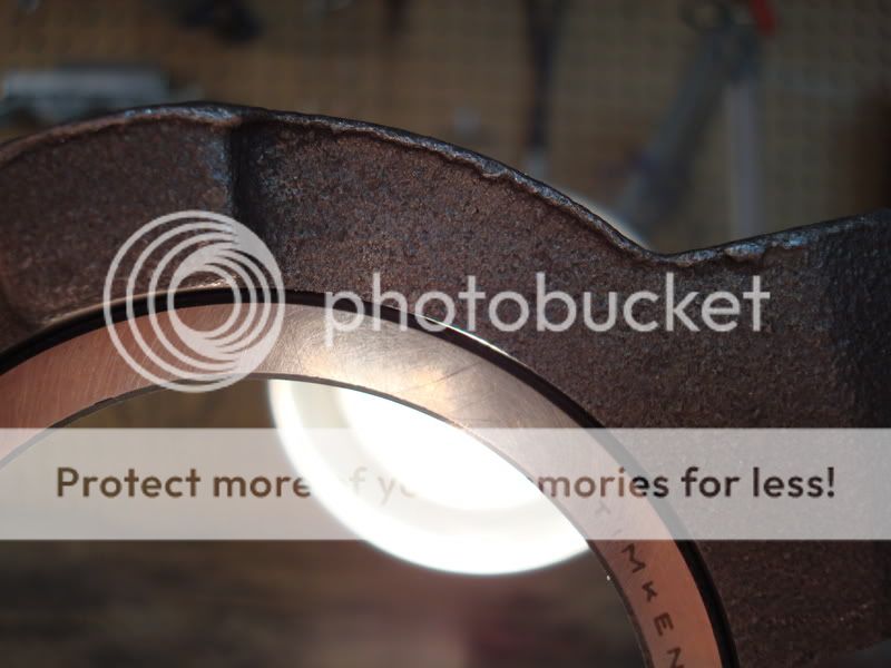
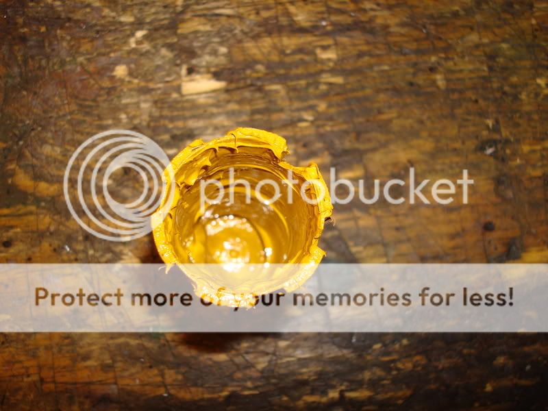
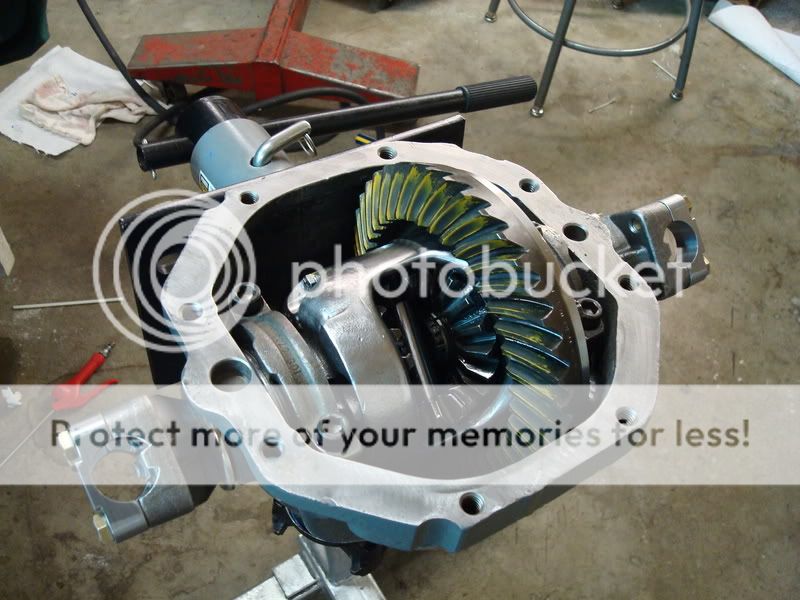
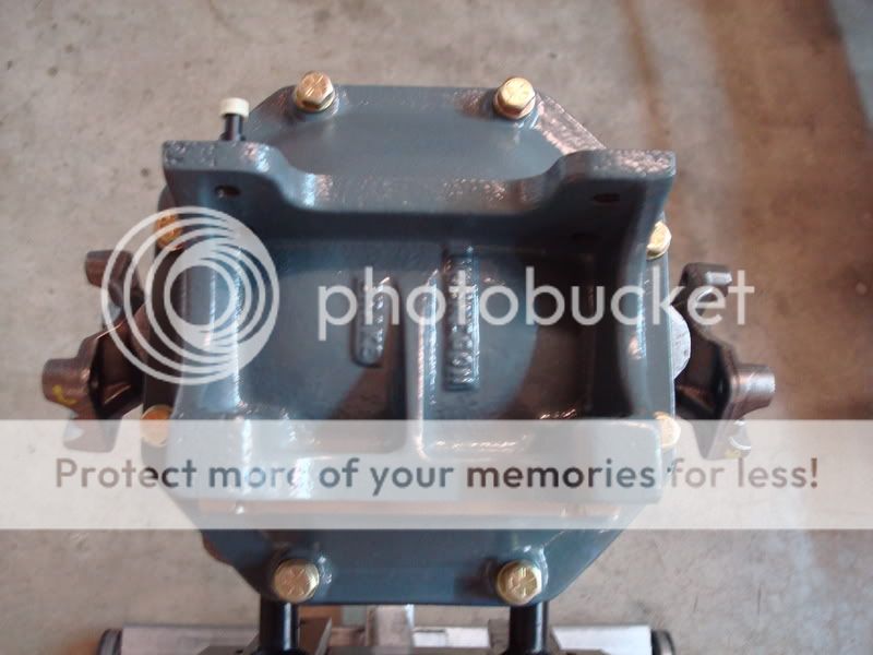
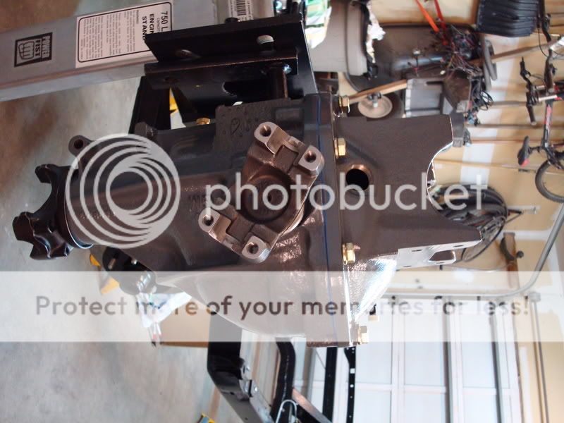
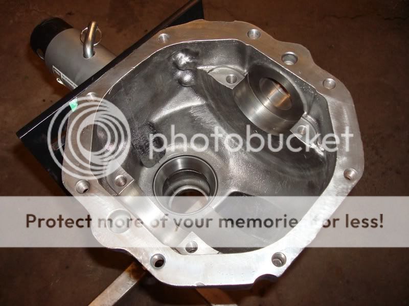
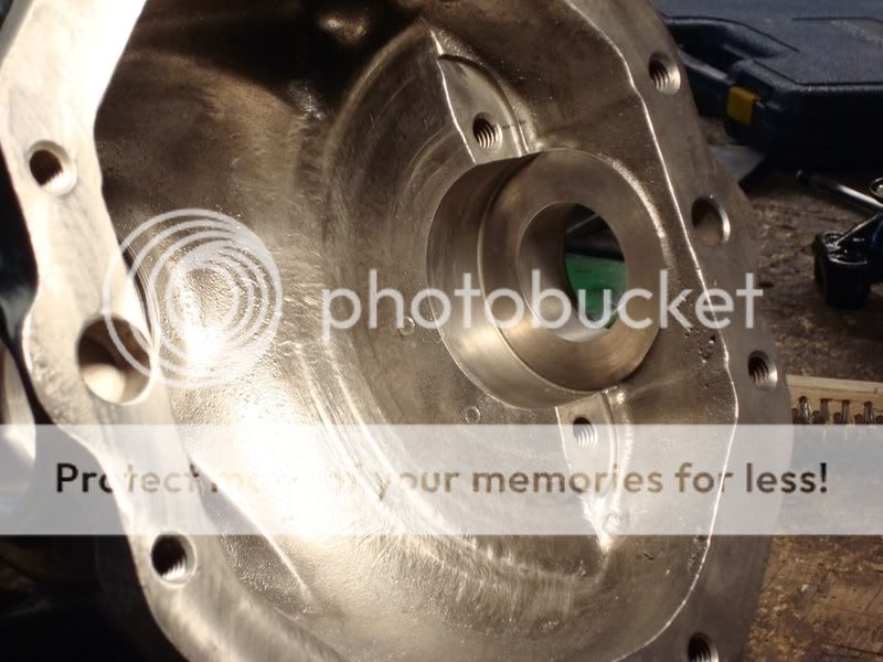
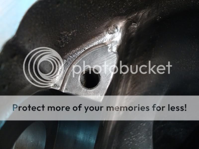
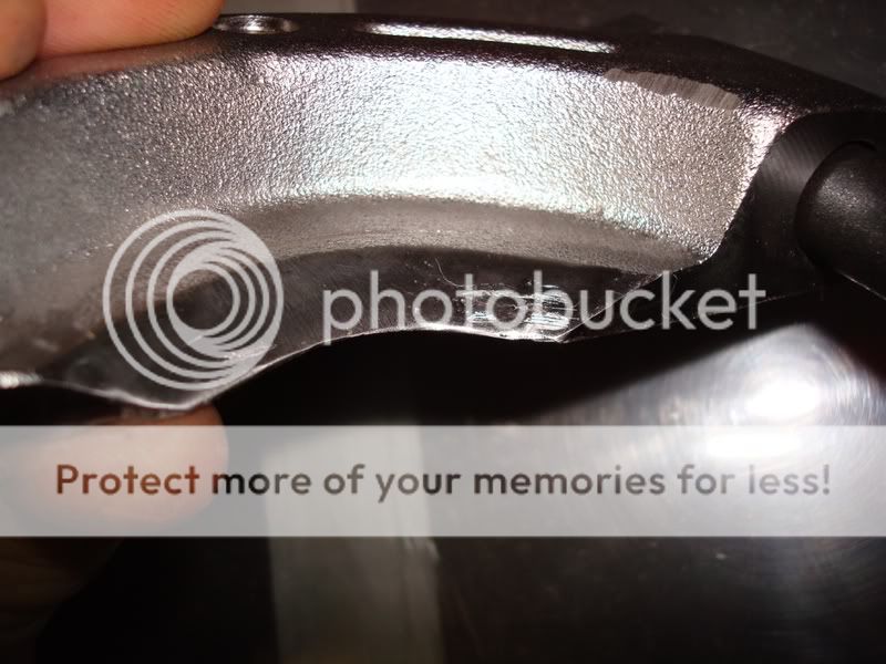
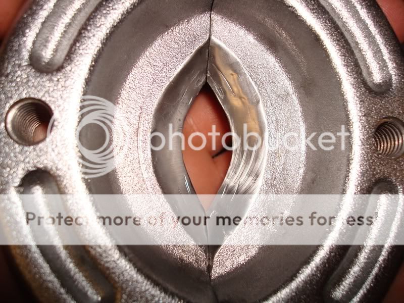
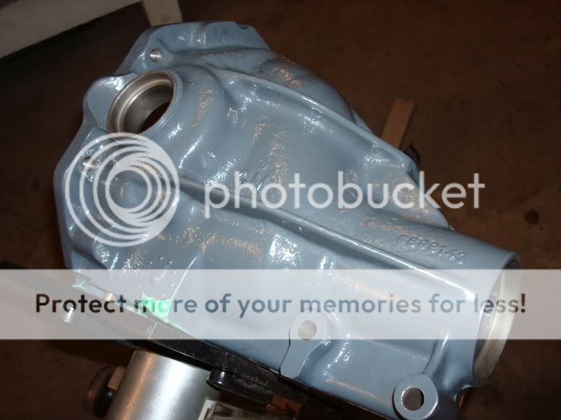
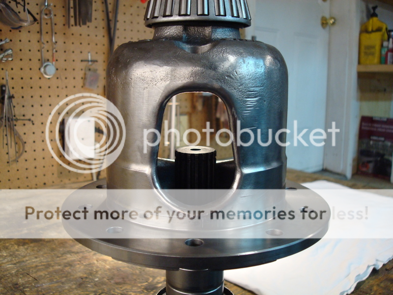
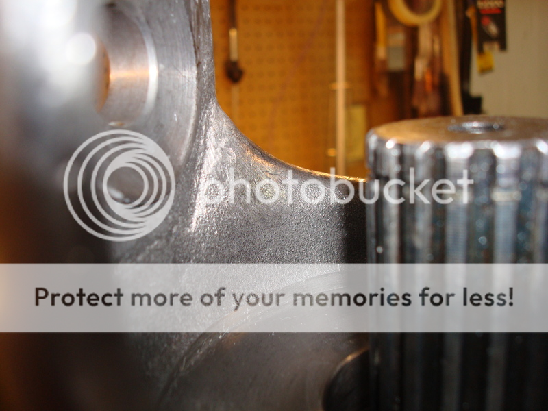
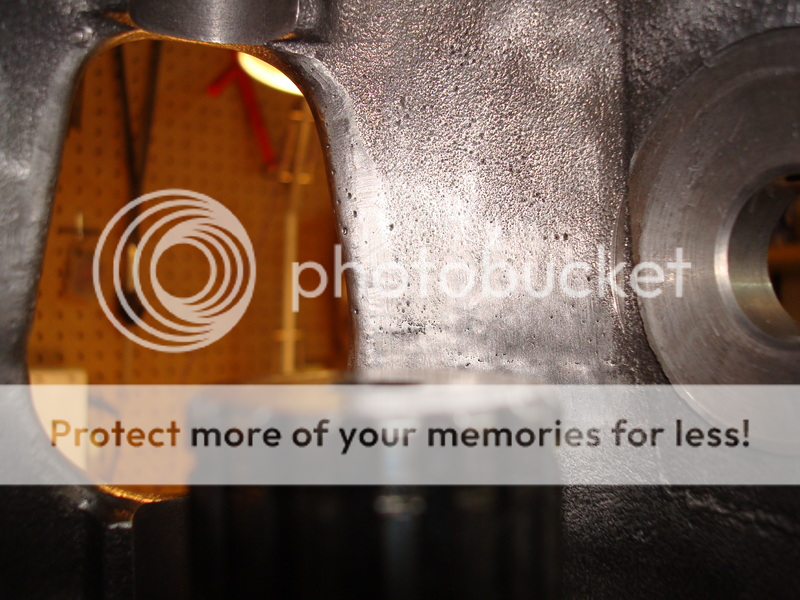
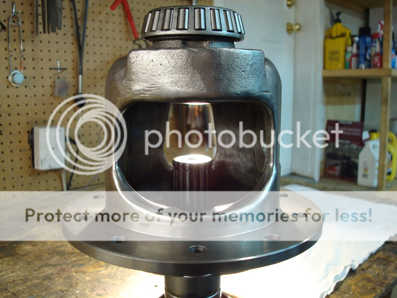
Once you get the diff removed from the vehicle, the first thing you want to do is go out and by yourself a cheap engine stand (3 wheeled) from Princess Auto (Canada’s form of Harbor Freight). The diff only weighs about a hundred pounds, so any engine stand will do. I can’t imagine anyone rebuilding a diff without this handy tool. It makes life so much easier, and reduces the amount of effort it actually takes to work on the thing; buy yourself one, it’s worth the money. I don’t have that many pictures from the beginning of the rebuild, so I will try to explain this the best I can. The first thing you want to do is mount the diff on the engine stand. Use two bolts in the strut bracket holes to mount it, and then place it on the stand. Unbolt the diff cover and then put an oil container on the floor. Turn the diff upside down and drain out all of the oil – turn the pinion a few times to help some of it pour out. Flip the diff back over and inspect the carrier and housing for any damage. Here are some pics of my damage. The previous owner must have lost a ring gear bolt and it chewed up the side of the housing – I used a die grinder and dremel to clean up the groove marks and make them baby smooth. I was lucky in that the bearing cap pads were in good shape otherwise.
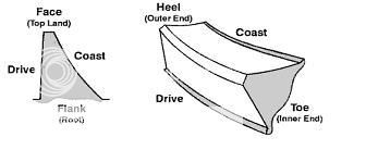
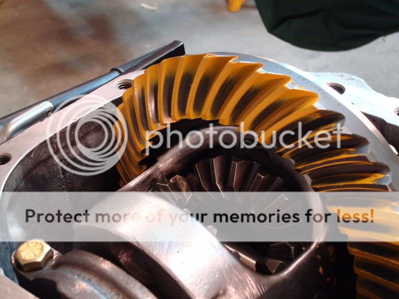
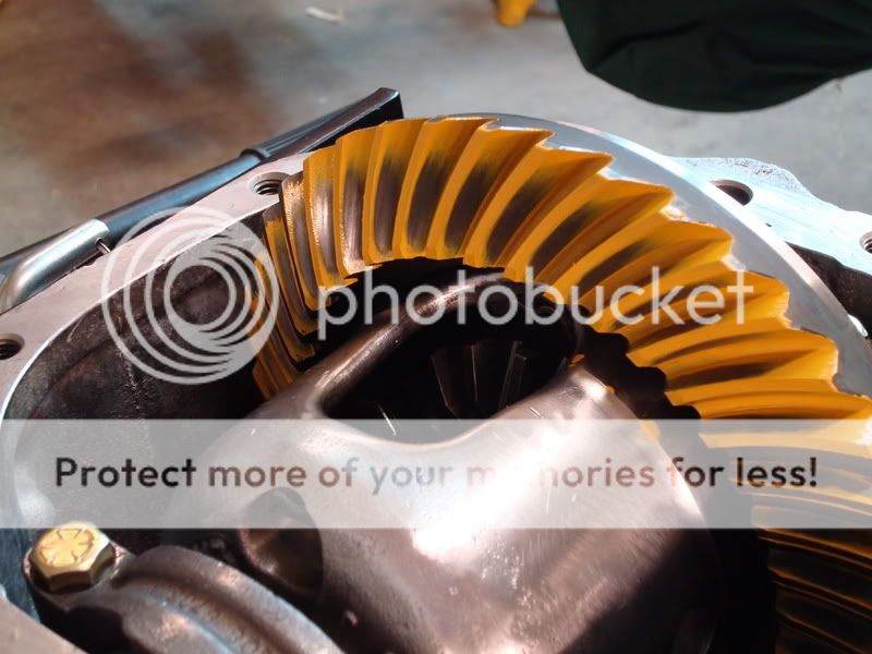
When it came to the gears, I bought new Toms 3.73’s. I would not attempt to reuse gears unless I knew how they sounded before tearing them apart – even then I won’t reuse them. The reason being is because if they sounded like crap before you tore everything apart, they can’t be made any better, as they have already worn into the pinion mesh, and trying to repattern them to get less noise out of them is a waste of time…you’ll never get a consistent pattern. I’ll never reuse gears in my entire life, even if they sounded good, because I don’t think it is worth it. If you plan on reusing your gears, you need to measure everything before you take it apart – shims, backlash, gear pattern…everything. You need to get it in the exact same setup when you reinstall everything, or else the gears will make noise and howl. I am not going to go into much detail here on how to do this, as I don’t have this type of experience (I didn’t reuse my gears, so I didn’t have to worry). I know how to setup new gears, but I don’t want to give you the wrong info if you plan on reusing used gears.
Get yourself a cheap pair of snap ring pliers, and remove the side yokes. They may be ground down and stuck inside the posi case – you might have to use a dremel tool to get the yokes out. It takes some careful grinding, but they should eventually slip out of the housing.
Now, Gary and Mike mention to mark the carrier caps before you remove them. I tore everything apart before marking them and they got mixed up. I had to figure out which cap was for which side. Even if you do mark them before you remove them, you still need to refit them to the housing saddles – bubba may have been in here before and reinstalled the caps on the wrong sides. I refit mine using a special trick I learned from Mike over the phone – this guy is incredible, he knows everything. So does Gary – he also is a genius. It’s too bad they live in different cities, because they would make one hell of a diff shop. These two fellows also check the fit of their caps, even if they did mark them before removing them from the housing. For now, use a sharpie to mark the carrier caps, as they may not be on the correct sides. Gary and Mike are the only people out there that fit their caps – no diff shop will do this. To fit a steel bearing cap, you will need a bridgeport mill and a surface grinder, both of which I don’t own. To fit a stock cap correctly is very easy, and requires basic hand tools and patience. I will go into detail on this later on in the paper, as you need to first clean the housing.
If you want the best differential out there, then you will not be reusing any of the bolts and washers in the differential – you’ll be buying all new grade 8 bolts. They’re cheap, and they are easy to get…replace them. Get yourself a box and some plastic Ziploc bags. As you remove parts, label the bags and then put the bags in the box. This will keep you organized, even if you never touch the parts again. I never did this when I disassembled everything. My dad did most of the disassembly, as this was supposed to be his project (sorry Dad). I ended up taking it over as I am a much bigger perfectionist than he is; I also wanted to learn how to rebuild a diff. After reading all of Mike’s and Gary’s post, and reading threads by people who had their stuff rebuilt by shops or vendors (and then their setups being worse than before they had them rebuilt), I said to myself screw it. I’m doing a frame off restoration; why not suck all this information out of these two guys so I have it for the rest of my life. If I ever had something farmed out, it would be to Mike or Gary, both for their quality of work and because of all the help they have given me.
Okay, so now you have the bearing caps removed and stored away. Next remove the carrier from the housing. Try to keep the side shim packs together so you can use them as a reference point when setting up the diff. If you reuse your gears, this is critical. If you install new gears (like me) then it isn’t that critical as you will need to redo everything anyways. When using new gears, you need to make sure that the carrier is nice and tight in the housing before you preload each of the shim packs – I will go into more detail on this later in the paper, as we are not near this rebuild phase yet. Put the carrier aside for now, we will disassemble and inspect this more later.
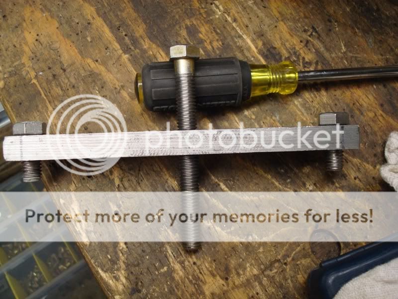
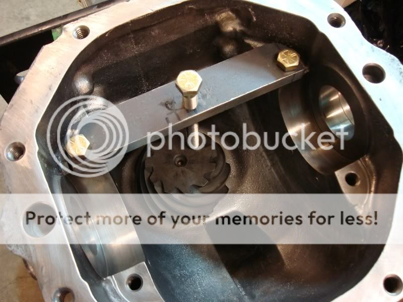
Now, if you are reusing your gears, you need to be extra careful that you don’t damage the pinion when removing it from the housing. Removing the pinion nut and then the pinion flange will let the pinion hit the floor (the outer bearing is not a press fit, it is slip fit). So for all you “used gear gurus†out there, now is the time to make your first homemade tool for the rebuild. You will use this tool a ton when you start assembling the diff, so put some work into it. It’s a pinion holder. All it is a piece of metal that has three holes drilled in it - two holes for bolts to go into the bearing pads, and a hole in the middle for a bolt. I tapped the center hole for the bolt, so you can tighten and loosen it to sit on the face of the pinion. You’ll probably not find this long of a bolt threaded this deep. I decided to use a tap and die set to make the threads go almost all the way to the top, not necessary, but I like to overdo things.
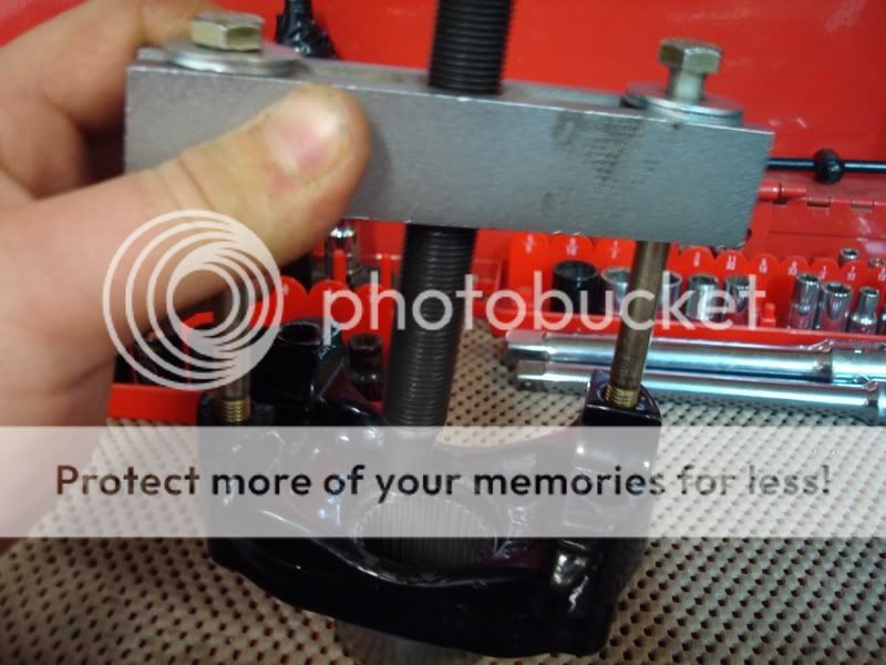
For the people out there that plan on using new gears, you don’t have to worry about hurting the used pinion. I for one didn’t care if the pinion hit the ground, because it was going to be used as a paperweight for the rest of its life anyways. So, when you remove the pinion nut and press off the pinion flange, keep your feet clear of its path (you don’t want any broken toes do you?). Here is what I used to pull off the flange, it worked great. It’s a tool from a bearing puller I bought, and two extra long bolts for the pinion flange holes. You will need this tool a lot when you setup the gear pattern, so you’re better off going out and buying one now. I think I saw a cheap small duty gear puller at Auto Value which might fit and work for this application, but you’d have to check to be sure.
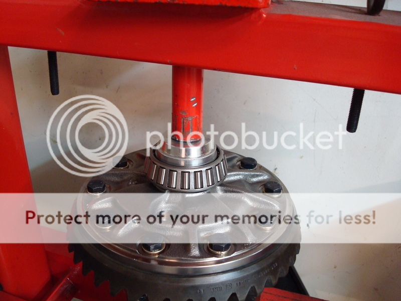
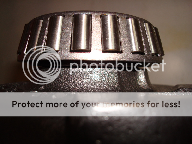
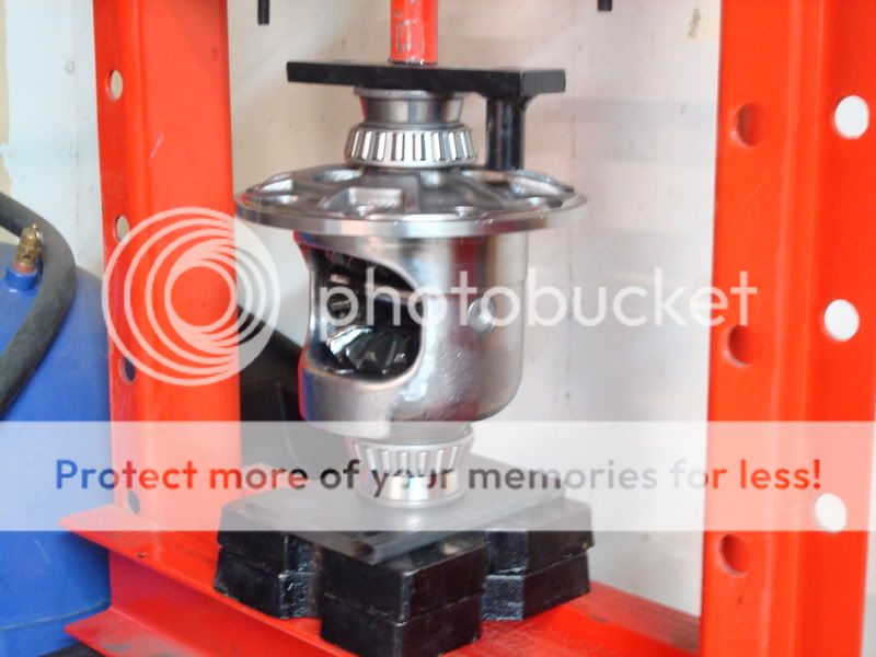
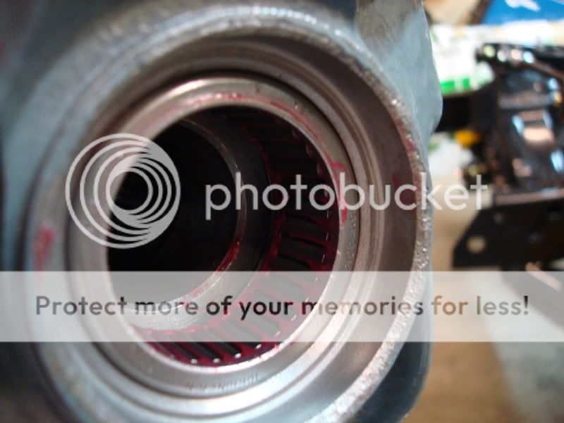
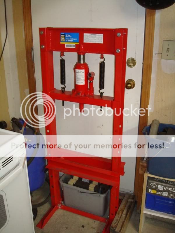
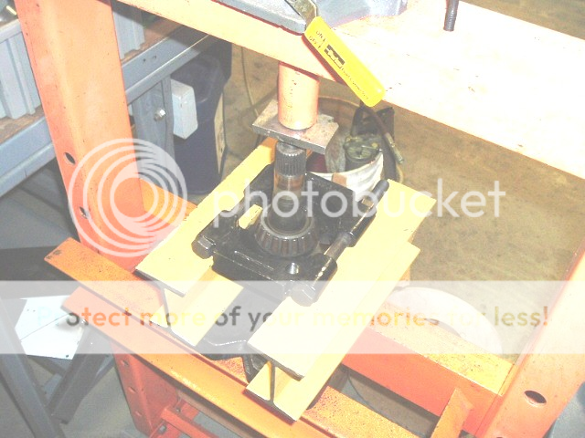
If your pinion is still stuck in the housing, do the following. Get your self a dead-blow rubber hammer and hit the pinion end while you hold your hand in the housing to catch the pinion. It should pop out with a little effort. Put the outer bearing in a Ziploc bag and in the box to keep you organized (you won’t be using that again anyways). Now it is time to remove the inner pinion bearing using a hydraulic press. Now, if you have a friend that is willing to let you borrow their hydraulic press for a few months, then do it. But if you just have a friend that says you can come over and use it whenever you want, then you will want to buy yourself a cheap one from Princess Auto (AKA Harbor Freight). The reason being is because it will get extremely old when you have to run over to his house every second day to press something else on…it honestly isn’t worth it. I hate buying tools from Princess Auto because they are always cheap quality and usually break or just don’t get the job done. I just couldn’t pass on this hydraulic press though, it was a steal. I think I paid $130 Canadian for the 12 ton press. If you were to build it yourself, that’s how much the steel would cost you to build the frame, so you are still saving yourself money. The hydraulic bottle will probably go in a couple of years, but you can get new hydraulic bottles from industrial places which are way better in quality, plus they are real easy to replace. I have used this unit to rebuild my trailing arms and steering box – it is great. I even used it to straighten out my steering bar, that saved me $100 alone. I believe Gary uses the exact same press, only he had to replace the hydraulic bottle because it crapped out. Other than that, this is a great tool (the diff is now finished as I write this paper, and the press is still going strong). Here is a pic of it:
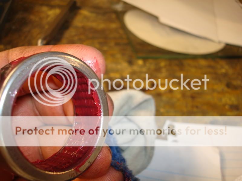
To press off the pinion bearing, you’ll need a bearing splitter. I bought one from Princess Auto when I got the press, and did a little mod to it. The pinion bearing is pressed tight on top of the pinion shim, which is underneath the bearing. It is very hard to remove it without damaging the cage. It’s not that critical if you damage the cage on this bearing, as it will be replaced anyways. But when it comes time to the final setup, you might have to press off the good bearing to change the shim size, even if the setup bearings were perfect with a certain shim. What I did was smooth out the inside of the bearing splitter so it fit underneath the bearing sides a little more. You can see what I did in this pic:
Here is a picture from Gary on how to press off the pinion bearing (I didn’t have a pic).
Now it’s time to buy yourself a micrometer or caliper. I bought myself a decent one which is digital, and it’s pretty damn accurate. It’s nothing to be proud of though, its mastercraft brand (from Canadian Tire), which I absolutely hate. The next time I rebuild a diff or trailing arms, I will be buying myself a nice expensive Starrett Caliper and dial indicator/base. I think I paid $50 for my caliper and I always test it against my feeler gauges, which go all the way down to 0.0015. Measure the original pinion shim and take note of it. I think my original shim was 0.026’’.
The next step is to remove the pinion bearing races using a brass drift and hammer. Go slowly as not to gouge the edges of where the race sits (if you do, its not a big deal, as a dremel tool with metal cutting wheel works nicely to chamfer the edge again).
Cleaning/Painting
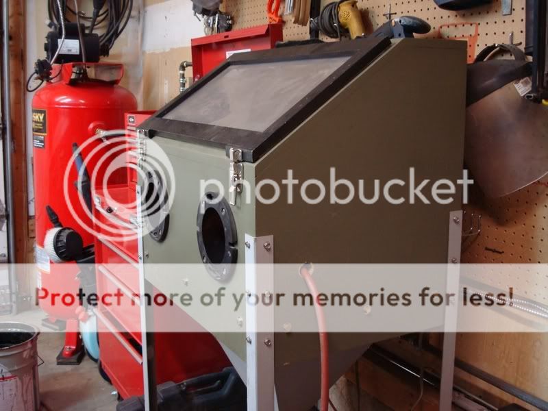
Now you have everything removed from the housing and it is time to clean it down to the bare metal. I had a bucket with a tightly sealed lid in the garage which fit perfect for the diff housing. I poured some gas, degreaser, soap and water into it and then mixed it all together. It will smell bad, so you need to keep the lid tightly sealed lid on it when it soaks in the garage. Place the housing in the mixture, put the lid on, and then let it sit for about 2-3 days. You’ll be amazed at how well this works. Hose the housing off with some water and soap, and it is down to the metal with minimal effort. The gas turns the oil into nothing…I couldn’t believe how well it worked. Then I taped off all the areas where sand could get into the housing, and sandblasted all the rust off. I built my own blast cabinet, which works great for projects like these.
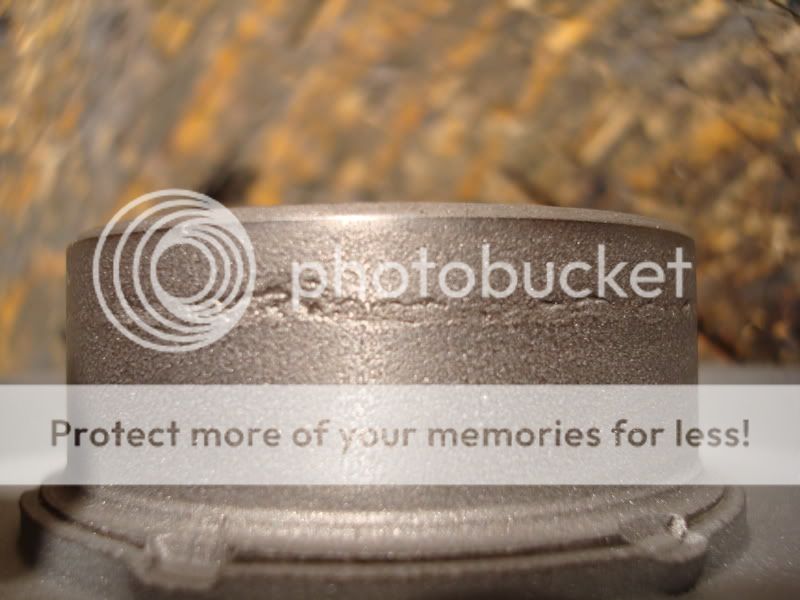
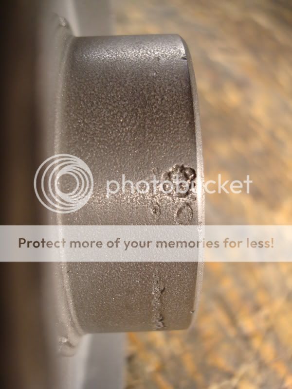
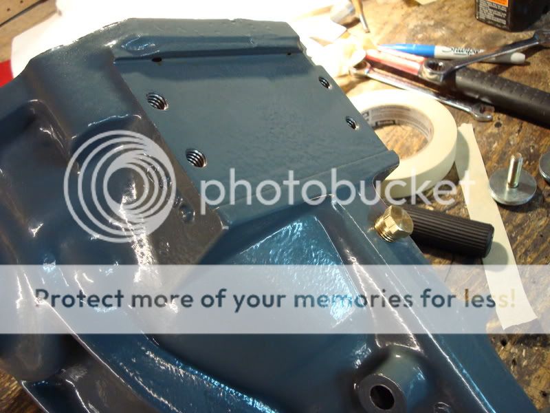
There are a few ways you can dress up the differential. The easiest and cheapest way is some spray paint from home depot. Lots of people seem to prefer the POR15 stuff, but I never really liked it ( I waited 3 days for a part to dry and it was still wet…after applying thin coats and following all the instructions down to the last letter). I think I may have got a bad batch. I decided to powdercoat my differential. The color is RAL7011:
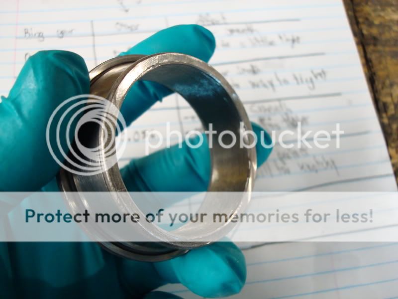
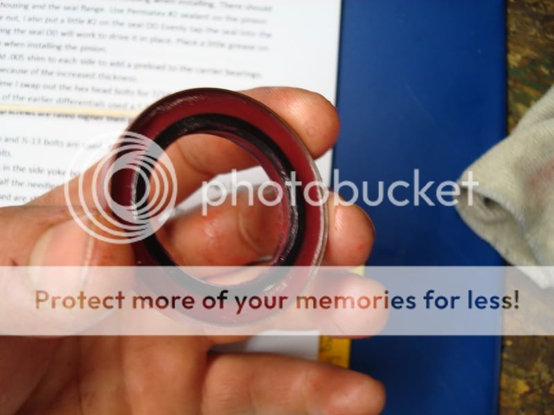
Paint the rest of your parts at this time as well (side yokes, diff cover, front differential bracket…). If you sandblast your yokes, be careful that you don’t sandblast the area where the seal rides. I accidentally did this and I was not comfortable reusing the yokes (I also wanted to upgrade to the hardened tip ones made by Lonestar.
Posi Case Disassembly
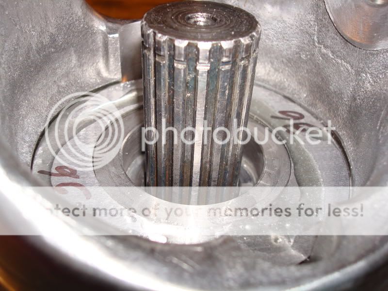
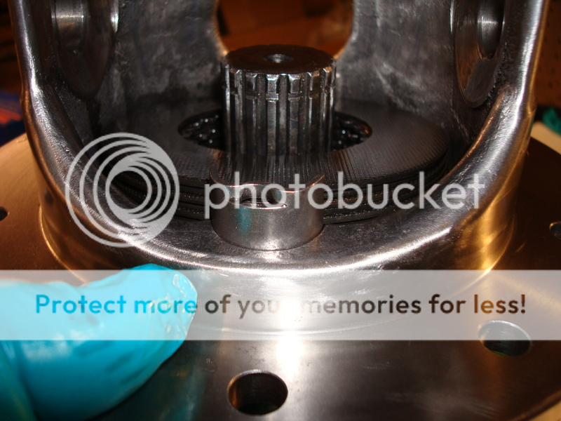
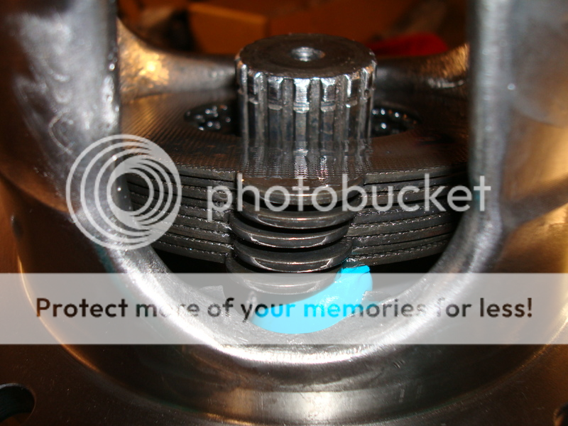
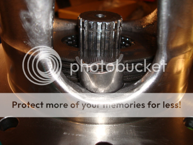
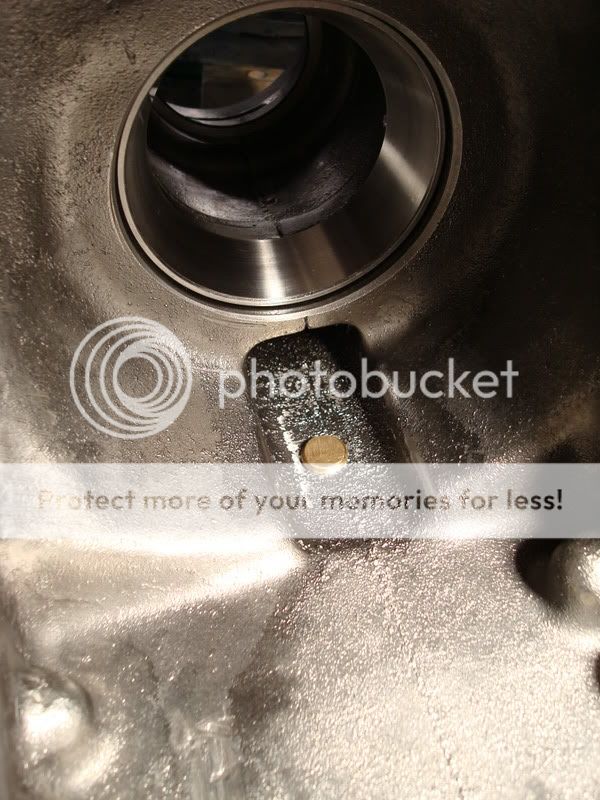
The first thing you want to do is remove the ring gear from the posi case. Take one of your old side yokes and put it in a vise, then place the posi case on top of the side yoke. It works great as a work stand. Use an impact gun to remove the ring gear bolts. The ring gear is a tight fit on the posi case, and you will need to use a hammer with a block of wood to remove it from the carrier. Work your way around the ring gear. If you are reusing you gears, be very careful – the ring gear will eventually pop loose and will fall and hit your vise. I tuned my posi unit without springs, so I wasn’t too concerned with ruining the springs. I cut them out with a dremel tool and cutting wheel. Remove the two plates that the springs were wedged between. Okay, now you are ready to remove the posi pin. PLEASE TAKE NOTE OF THIS!!!!!!!! The pin is not a press fit; it is a slip fit which is held in place with a screw/pin in the carrier. I originally thought it was a press fit, and that I had to press the pin out. So, off I went to my hydraulic press, and pressed out the large posi pin – little did I know that the pin was held in place horizontally with another long pin, and I ruined my posi case. DO NOT PRESS OUT YOUR PIN!!!! First, you need to remove pin #3 in the following diagram…
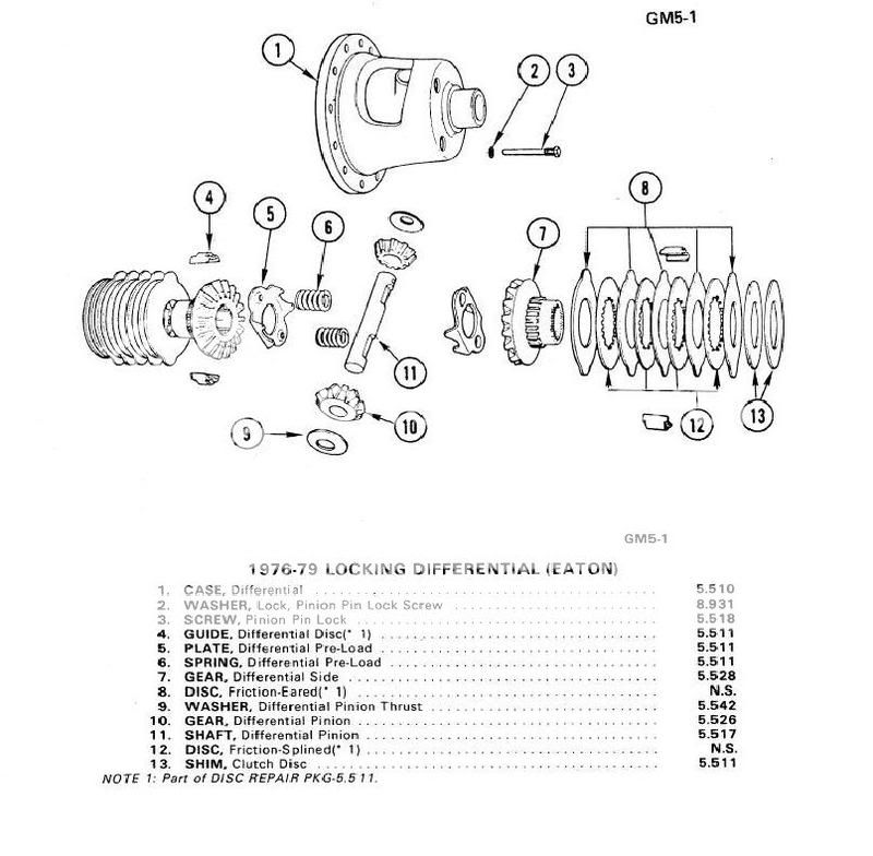
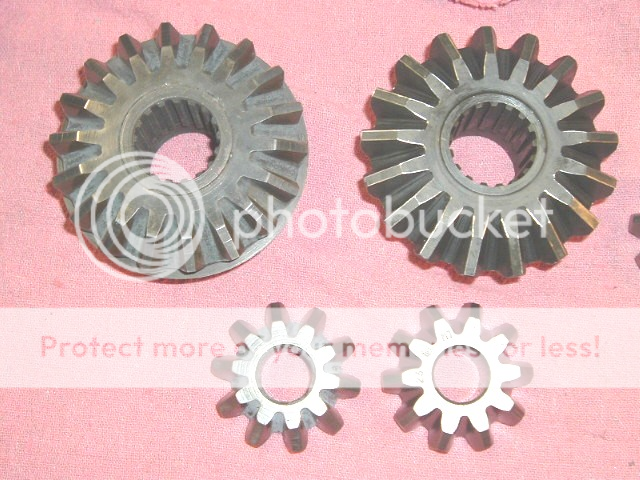
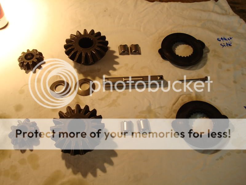
After you remove this pin, then you can slip the larger pin (#11 in the diagram) out of the housing using your finger. It is a slip fit, not a press fit, so it can be removed with little effort. I had to replace my posi case due to this one mistake – the small pin was crushed when I pressed out the larger pin, and the hole was elongated and broken…a really costly mistake on my part. Once you have removed these two items, you can remove the spider gears. Turn the posi unit by hand until the spider thrust washers drop out from behind the gears and then remove them (you won’t be reusing the thrust washers). Once you remove the spider gears (#10), then the top gear with its respected clutches and retainers will drop down and you can remove them from the carrier. All that is left to do is remove the bottom gear, which the side yoke is sitting on, and set it aside with its clutches and 2 retainers. You will not be reusing the clutches or retainers in the rebuild. However, if your spider gears are in good condition, then you may reuse them. There are two different types of gears – 17 tooth and 18 tooth. The 18 tooth gears are not as strong as the 17 tooth gears. Here is a picture from Gary regarding the difference between them (the good ones, and the ones you want, are on the right side). If you happen to have the 18 tooth gears, I’d replace them now. They are not as strong as the 17 tooth ones.
Degrease and clean the posi case, spider gears, large posi pin, and small pin/screw. Store the clutches and retainers in a zip loc bag. I also forgot to mention that the posi case sometimes has 2-3 shims on each side of the carrier – this was done by your folks at GM to pick up the slack in the case.
Carrier Inspection
You can reuse the carrier as long as it is not damaged and does not have any cracks in it. The large posi pin often elongates the machined holes in the carrier – if it is oblong, you will have to machine it for a larger pin or gears (I think Tom’s differentials does this), or replace the carrier. Look for any cracks and damage. One crack and it is toast unfortunately…don’t risk it, replace it now. All this work you’ll be doing will be for nothing if you have a bad carrier, as it will eventually go and ruin your entire diff.
Polishing the Posi Case
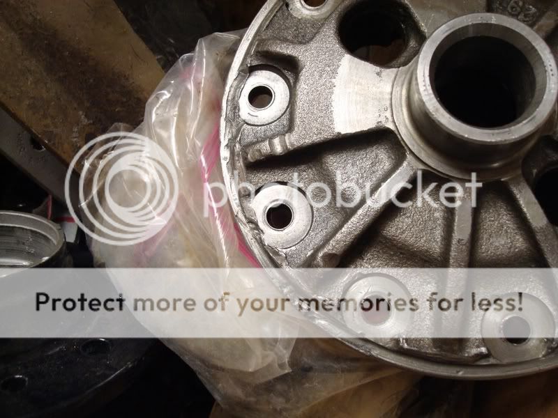
Now you are ready to start tuning your posi unit – it takes a lot of time to do, but it will be worth it in the end. The first thing you want to do is protect the surfaces that you don not want to polish (I used duct tape, as it is much more sticky than masking tape). Tape off the areas where the spider gear thrust washers ride – these areas are very important and you don’t want to ruin or scratch these. You will need a few tools for this job. I used a carbide burr with a dremel tool, die grinder and grinding stones, sandpaper, emery cloth and some roloc disks on a surface prep tool my dad bought me. The basic principle of this job is to remove all the stress areas from the casing – this will prolong the life of your diff, as well as make it much stronger than stock. If you look inside the casing, you’ll notice some “seams†from the casting process. You want to polish these areas as well. When you polish the windows on the carrier, you have to be careful not to continue the polishing past where the clutches ride, but you do want to carry the polishing inside the housing to the areas where the clutches don’t ride. I hope this makes sense. Here is what my new case looked like when I got it in the mail:
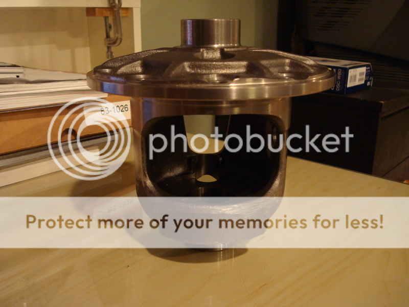
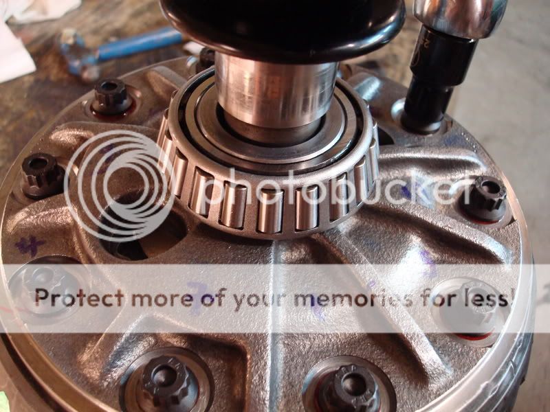
Here is the case after polishing (please ignore the carrier bearings, some of these pictures were taken after I decided to redo my work, and they are the best pics I have)…
After the polishing of the posi case is completed, you are ready to move onto the next step.
ARP Ring Gear Bolts
If you plan on using ARP ring gear bolts with your rebuild, now is the time to countersink the holes on you posi case. Gary touched base on this in one of his posts. Basically, what he found was there was a shoulder on the ARP bolts which prevented them from seating flat. The case I bought from Gary already had the holes countersunk, so that saved me from having to do it. A step drill might work to slightly countersink the holes too, but you'd have to ask Gary about that one. This step is mentioned in ARP’s instructions as well.
Beveling the Spider Gears
GM left a lot of slack in the original spring setup – the reason they installed the springs was to take up this slack by putting pressure on the side clutches. The clutches are designed so that they provide resistance when they are turned. By changing the spring rate in the posi unit, all you are doing is reducing side pressure on the clutches, which results in either more posi action or less posi action. They had to install springs because it was not cost effective to tune each unit by hand so there was no slack in the clutches – leaving the springs out would mean that the clutches would not drag across each other and provide no resistance. Thus, instead of the wheel turning at a different rate, it would be extremely sloppy and the spider gear tooth contact would be minimal. When both wheels are turning at the same rate, the 10 tooth spider gears prevent the clutches from turning. One spider gear wants to go left, and one spider gear wants to go right, and they lock up and turn at the same rate like a fixed axle. Thus, there really is no need for posi springs as long as you remove the slack GM left in the setup by shimming the side clutches properly. Too tight, and the clutches act just like the GM setup, and the wear on them will be excessive. Too loose and the spider gear tooth contact will be minimal and weak – and the clutches will not drag across each other providing a smooth motion. This is very time consuming, but it is worth it in the end. GM decided to try and fix their hammering issue by installing snowflake clutches to get more oil between the already stressed side clutches…now all this did was weaken them to the point that they would break.
You are going to be pulling the tolerances in very close, so you want to bevel the four posi gears’ edges. I used a dremel and a grinding stone attachment; just walk the grinding stone across the edges, don't apply any pressure (you want to break the sharp corners).

Parts
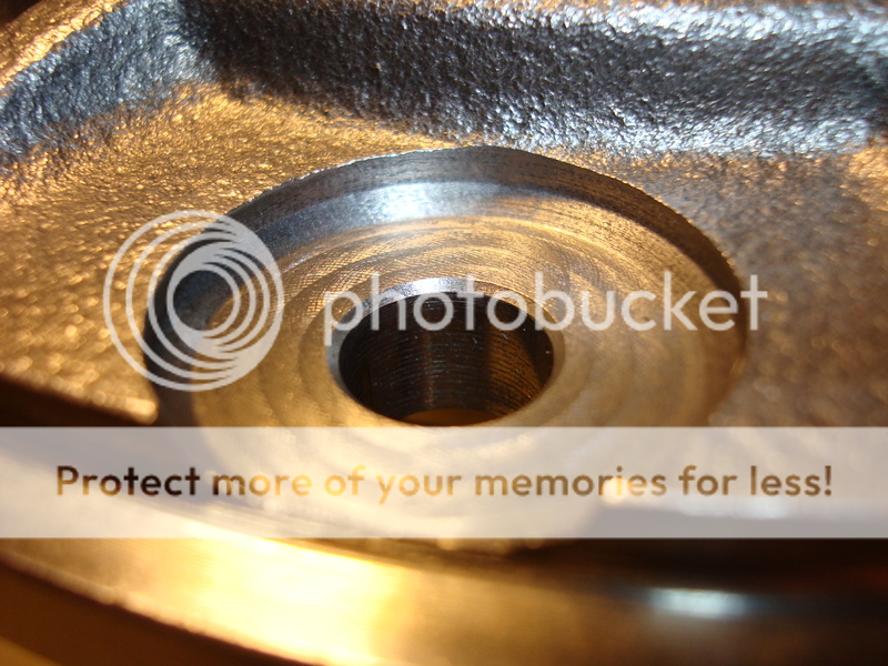
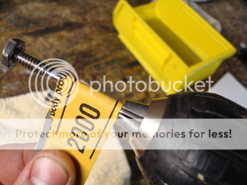
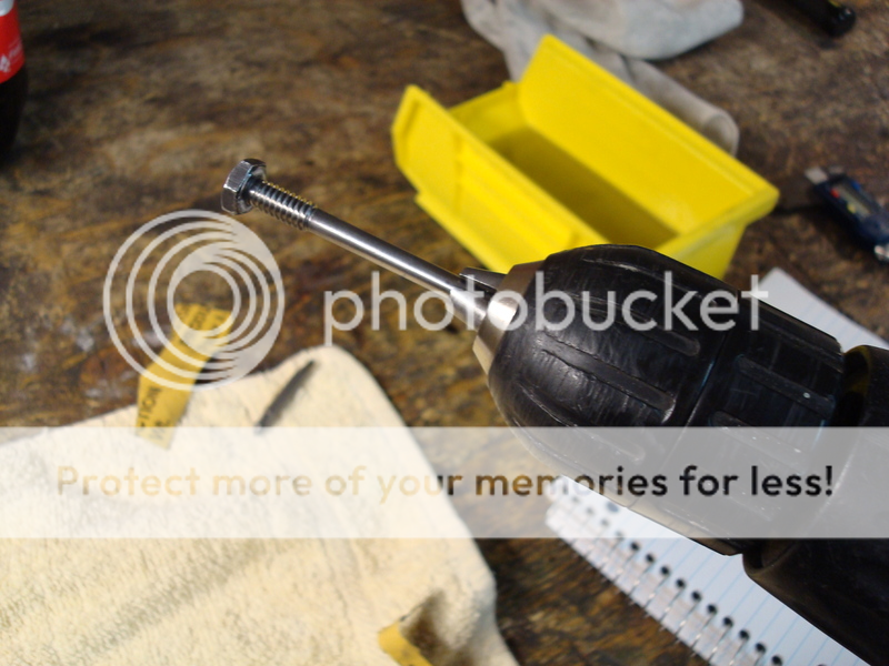
You will need to buy yourself a new set of solid clutches, a clutch shim kit, new clutch retainers and new spider thrust washers. The clutch shim kit comes with two sets of 0.010’’-0.045’’ shims in increments of 0.005’’. You will also need to get a hold of some GM posi additive for use when tuning the posi unit. Look over your crosshaft for any wear/tear. The OD of the top and bottom should be 0.747’’, and there should be no signs of the yokes wearing on the shaft. The ID of the holes in the posi case I think are 0.749’’. If it is not up to spec, replace it. Gary sells a shaft that is 0.001’’ oversize, and it is a much tighter fit. That is the one that I used during my rebuild. You also want to check the screw/pin that holds the crosshaft in place. The new pins that GM is making and selling are apparently bad quality compared to the originals - the heads break off real easy if tightened too much, and then you are screwed (no pun intended). I was lucky in getting an original GM one. I think these pins are around 18 bucks, so they aren't cheap. You want to check and see if there is a "step" in the shank of it. If there is, it should be replaced. Go back to that diagram I posted above, and look at item number 2. It is an internal ¼’’ spring washer. You will need to get a new one (I got a 100 pack from Acklands Grainger). Install it when the posi tuning is completed, as you can only use it once. DO NOT REUSE YOUR OLD ONE! I polished the screw/pin that goes through the cross shaft in the posi case using my drill as a mini lathe…
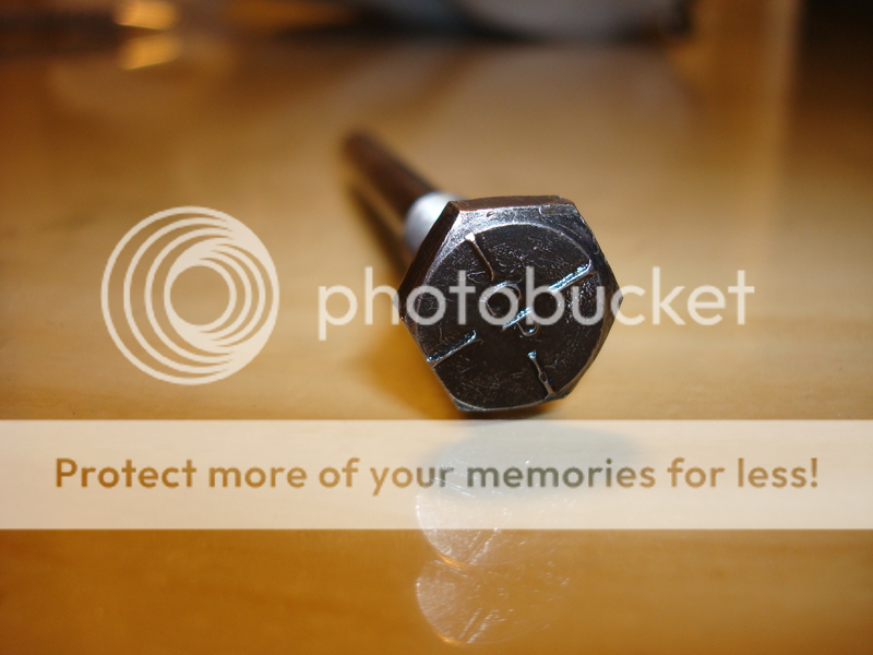
This is what an original GM Posi screw/pin looks like on the head…
Posi Tuning
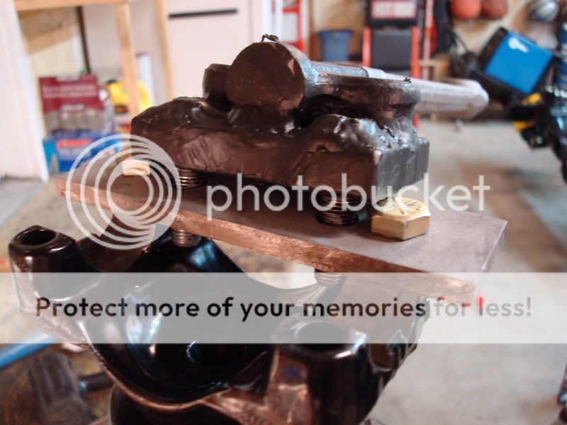
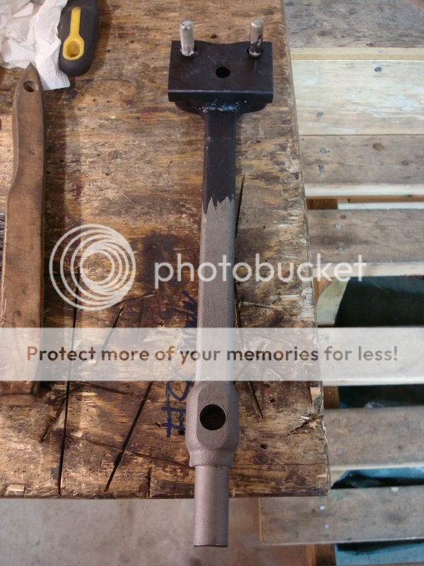
Before you start tuning the posi unit, you need to make yourself another homemade tool. It is a spanner wrench for turning the unit so you can seat the clutches. I took an old lower control arm shaft I had laying around, welded a 1/2'' plate to the end and then welded two bolts to it. The two bolts fit into two of the holes on the posi case, which allows you to turn it with extra leverage. I coated the end of it in some black rubber I had laying around - it prevented me from accidentally scratching my posi case when I was working on it.
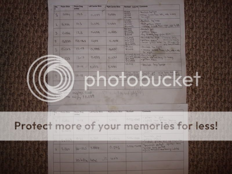
After you make your new homemade tool, you are ready to start the posi tuning procedure. I really had to climb into Gary’s head and understand what he was explaining to me as to what he feels when he tunes a posi unit. You wouldn’t believe how many questions I asked him – I’m OCD when it comes to stuff like this.
I clean everything with brake cleaner and compressed air. The next step is to sort out the clutches. They are stamped differently on each side. If you draw you fingernail around the edges, you'll immediately know which side has the deeper stamping. Take a sharpie and put a small "d" on the deeper face so you don't have to keep checking when assembling. The marker will eventually wear off from the oil, but it will keep you organized. I asked Gary as to whether it mattered which way the two clutch packs faced (do all the deep stampings for both sides need to face to the left, or to the right). He said it didn't matter, but you need to keep the deep faces facing in one direction for each clutch pack. Lay all your parts onto a clean rag - once again, this will keep you organized. Oil the clutches with GM posi additive.
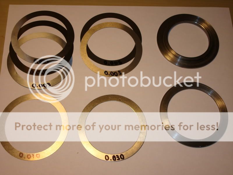
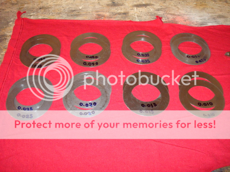
Alright, here is where all the patience on this project comes in - figuring out which size shim is required to set up the posi case. Here is a shot of all the shims that came in Gary's kit...
By Jeremy Smith
If you want the absolute best job out there, you can do it a few ways. One, you can send your diff to Mike Dyer (tracdogg2) or Gary Ramadei (GTR1999), OR you can build it yourself to their standards – which will probably cost you a little more because you have to buy the correct tools, pay for your mistakes (which will happen, trust me on this one), and build yourself custom tools…but you will have them for the rest of your life (and you can say that you built it!). I suggest you get in contact with them whether you plan on rebuilding your differential yourself or are having them rebuild it for you. I for one will no longer buy diff parts without first contacting Gary or Mike – they are straight up and only sell quality stuff.
I am writing this rebuild paper out of my own will. I do not intend to take any business away from the Corvette vendors out there – I am just a regular guy who likes to build stuff, that’s it. I’m only 18, and don’t even have the abilities to start a differential business. Sure I’ll help guys rebuild their diff and answer questions, but I’m not taking in work to compete with the vendors. I don’t have the time, money or even the facilities for that matter. This paper is designed to assist those who want to take on the task of rebuilding a diff by themselves.
If you have any doubt about your abilities to rebuild a diff, then send it out to get rebuilt by a professional. I am not liable for any of the work you do.
First Inspection/Disassembly of Unit
Once you get the diff removed from the vehicle, the first thing you want to do is go out and by yourself a cheap engine stand (3 wheeled) from Princess Auto (Canada’s form of Harbor Freight). The diff only weighs about a hundred pounds, so any engine stand will do. I can’t imagine anyone rebuilding a diff without this handy tool. It makes life so much easier, and reduces the amount of effort it actually takes to work on the thing; buy yourself one, it’s worth the money. I don’t have that many pictures from the beginning of the rebuild, so I will try to explain this the best I can. The first thing you want to do is mount the diff on the engine stand. Use two bolts in the strut bracket holes to mount it, and then place it on the stand. Unbolt the diff cover and then put an oil container on the floor. Turn the diff upside down and drain out all of the oil – turn the pinion a few times to help some of it pour out. Flip the diff back over and inspect the carrier and housing for any damage. Here are some pics of my damage. The previous owner must have lost a ring gear bolt and it chewed up the side of the housing – I used a die grinder and dremel to clean up the groove marks and make them baby smooth. I was lucky in that the bearing cap pads were in good shape otherwise.
When it came to the gears, I bought new Toms 3.73’s. I would not attempt to reuse gears unless I knew how they sounded before tearing them apart – even then I won’t reuse them. The reason being is because if they sounded like crap before you tore everything apart, they can’t be made any better, as they have already worn into the pinion mesh, and trying to repattern them to get less noise out of them is a waste of time…you’ll never get a consistent pattern. I’ll never reuse gears in my entire life, even if they sounded good, because I don’t think it is worth it. If you plan on reusing your gears, you need to measure everything before you take it apart – shims, backlash, gear pattern…everything. You need to get it in the exact same setup when you reinstall everything, or else the gears will make noise and howl. I am not going to go into much detail here on how to do this, as I don’t have this type of experience (I didn’t reuse my gears, so I didn’t have to worry). I know how to setup new gears, but I don’t want to give you the wrong info if you plan on reusing used gears.
Get yourself a cheap pair of snap ring pliers, and remove the side yokes. They may be ground down and stuck inside the posi case – you might have to use a dremel tool to get the yokes out. It takes some careful grinding, but they should eventually slip out of the housing.
Now, Gary and Mike mention to mark the carrier caps before you remove them. I tore everything apart before marking them and they got mixed up. I had to figure out which cap was for which side. Even if you do mark them before you remove them, you still need to refit them to the housing saddles – bubba may have been in here before and reinstalled the caps on the wrong sides. I refit mine using a special trick I learned from Mike over the phone – this guy is incredible, he knows everything. So does Gary – he also is a genius. It’s too bad they live in different cities, because they would make one hell of a diff shop. These two fellows also check the fit of their caps, even if they did mark them before removing them from the housing. For now, use a sharpie to mark the carrier caps, as they may not be on the correct sides. Gary and Mike are the only people out there that fit their caps – no diff shop will do this. To fit a steel bearing cap, you will need a bridgeport mill and a surface grinder, both of which I don’t own. To fit a stock cap correctly is very easy, and requires basic hand tools and patience. I will go into detail on this later on in the paper, as you need to first clean the housing.
If you want the best differential out there, then you will not be reusing any of the bolts and washers in the differential – you’ll be buying all new grade 8 bolts. They’re cheap, and they are easy to get…replace them. Get yourself a box and some plastic Ziploc bags. As you remove parts, label the bags and then put the bags in the box. This will keep you organized, even if you never touch the parts again. I never did this when I disassembled everything. My dad did most of the disassembly, as this was supposed to be his project (sorry Dad). I ended up taking it over as I am a much bigger perfectionist than he is; I also wanted to learn how to rebuild a diff. After reading all of Mike’s and Gary’s post, and reading threads by people who had their stuff rebuilt by shops or vendors (and then their setups being worse than before they had them rebuilt), I said to myself screw it. I’m doing a frame off restoration; why not suck all this information out of these two guys so I have it for the rest of my life. If I ever had something farmed out, it would be to Mike or Gary, both for their quality of work and because of all the help they have given me.
Okay, so now you have the bearing caps removed and stored away. Next remove the carrier from the housing. Try to keep the side shim packs together so you can use them as a reference point when setting up the diff. If you reuse your gears, this is critical. If you install new gears (like me) then it isn’t that critical as you will need to redo everything anyways. When using new gears, you need to make sure that the carrier is nice and tight in the housing before you preload each of the shim packs – I will go into more detail on this later in the paper, as we are not near this rebuild phase yet. Put the carrier aside for now, we will disassemble and inspect this more later.
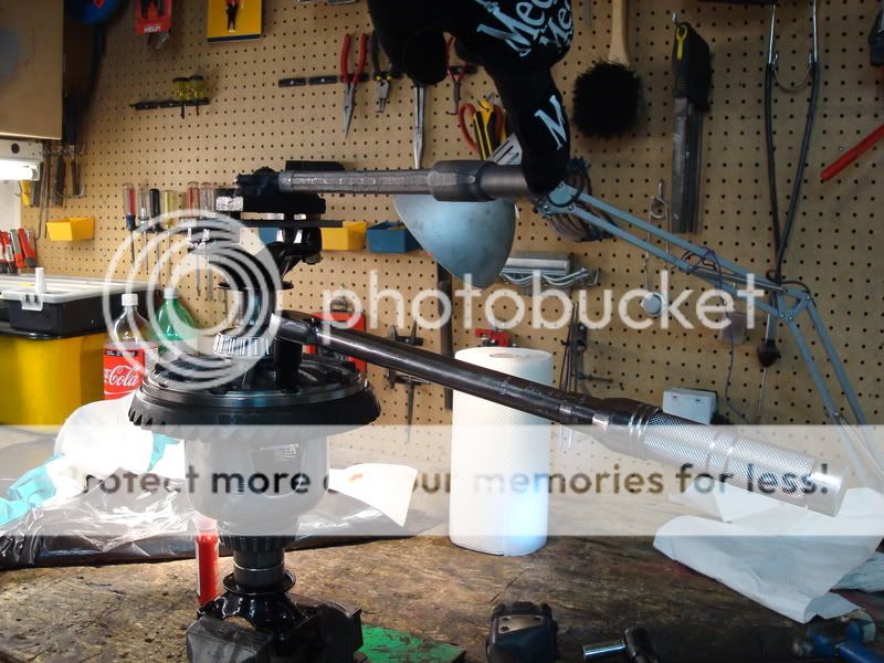
Now, if you are reusing your gears, you need to be extra careful that you don’t damage the pinion when removing it from the housing. Removing the pinion nut and then the pinion flange will let the pinion hit the floor (the outer bearing is not a press fit, it is slip fit). So for all you “used gear gurus†out there, now is the time to make your first homemade tool for the rebuild. You will use this tool a ton when you start assembling the diff, so put some work into it. It’s a pinion holder. All it is a piece of metal that has three holes drilled in it - two holes for bolts to go into the bearing pads, and a hole in the middle for a bolt. I tapped the center hole for the bolt, so you can tighten and loosen it to sit on the face of the pinion. You’ll probably not find this long of a bolt threaded this deep. I decided to use a tap and die set to make the threads go almost all the way to the top, not necessary, but I like to overdo things.
For the people out there that plan on using new gears, you don’t have to worry about hurting the used pinion. I for one didn’t care if the pinion hit the ground, because it was going to be used as a paperweight for the rest of its life anyways. So, when you remove the pinion nut and press off the pinion flange, keep your feet clear of its path (you don’t want any broken toes do you?). Here is what I used to pull off the flange, it worked great. It’s a tool from a bearing puller I bought, and two extra long bolts for the pinion flange holes. You will need this tool a lot when you setup the gear pattern, so you’re better off going out and buying one now. I think I saw a cheap small duty gear puller at Auto Value which might fit and work for this application, but you’d have to check to be sure.
If your pinion is still stuck in the housing, do the following. Get your self a dead-blow rubber hammer and hit the pinion end while you hold your hand in the housing to catch the pinion. It should pop out with a little effort. Put the outer bearing in a Ziploc bag and in the box to keep you organized (you won’t be using that again anyways). Now it is time to remove the inner pinion bearing using a hydraulic press. Now, if you have a friend that is willing to let you borrow their hydraulic press for a few months, then do it. But if you just have a friend that says you can come over and use it whenever you want, then you will want to buy yourself a cheap one from Princess Auto (AKA Harbor Freight). The reason being is because it will get extremely old when you have to run over to his house every second day to press something else on…it honestly isn’t worth it. I hate buying tools from Princess Auto because they are always cheap quality and usually break or just don’t get the job done. I just couldn’t pass on this hydraulic press though, it was a steal. I think I paid $130 Canadian for the 12 ton press. If you were to build it yourself, that’s how much the steel would cost you to build the frame, so you are still saving yourself money. The hydraulic bottle will probably go in a couple of years, but you can get new hydraulic bottles from industrial places which are way better in quality, plus they are real easy to replace. I have used this unit to rebuild my trailing arms and steering box – it is great. I even used it to straighten out my steering bar, that saved me $100 alone. I believe Gary uses the exact same press, only he had to replace the hydraulic bottle because it crapped out. Other than that, this is a great tool (the diff is now finished as I write this paper, and the press is still going strong). Here is a pic of it:
To press off the pinion bearing, you’ll need a bearing splitter. I bought one from Princess Auto when I got the press, and did a little mod to it. The pinion bearing is pressed tight on top of the pinion shim, which is underneath the bearing. It is very hard to remove it without damaging the cage. It’s not that critical if you damage the cage on this bearing, as it will be replaced anyways. But when it comes time to the final setup, you might have to press off the good bearing to change the shim size, even if the setup bearings were perfect with a certain shim. What I did was smooth out the inside of the bearing splitter so it fit underneath the bearing sides a little more. You can see what I did in this pic:
Here is a picture from Gary on how to press off the pinion bearing (I didn’t have a pic).
Now it’s time to buy yourself a micrometer or caliper. I bought myself a decent one which is digital, and it’s pretty damn accurate. It’s nothing to be proud of though, its mastercraft brand (from Canadian Tire), which I absolutely hate. The next time I rebuild a diff or trailing arms, I will be buying myself a nice expensive Starrett Caliper and dial indicator/base. I think I paid $50 for my caliper and I always test it against my feeler gauges, which go all the way down to 0.0015. Measure the original pinion shim and take note of it. I think my original shim was 0.026’’.
The next step is to remove the pinion bearing races using a brass drift and hammer. Go slowly as not to gouge the edges of where the race sits (if you do, its not a big deal, as a dremel tool with metal cutting wheel works nicely to chamfer the edge again).
Cleaning/Painting
Now you have everything removed from the housing and it is time to clean it down to the bare metal. I had a bucket with a tightly sealed lid in the garage which fit perfect for the diff housing. I poured some gas, degreaser, soap and water into it and then mixed it all together. It will smell bad, so you need to keep the lid tightly sealed lid on it when it soaks in the garage. Place the housing in the mixture, put the lid on, and then let it sit for about 2-3 days. You’ll be amazed at how well this works. Hose the housing off with some water and soap, and it is down to the metal with minimal effort. The gas turns the oil into nothing…I couldn’t believe how well it worked. Then I taped off all the areas where sand could get into the housing, and sandblasted all the rust off. I built my own blast cabinet, which works great for projects like these.
There are a few ways you can dress up the differential. The easiest and cheapest way is some spray paint from home depot. Lots of people seem to prefer the POR15 stuff, but I never really liked it ( I waited 3 days for a part to dry and it was still wet…after applying thin coats and following all the instructions down to the last letter). I think I may have got a bad batch. I decided to powdercoat my differential. The color is RAL7011:
Paint the rest of your parts at this time as well (side yokes, diff cover, front differential bracket…). If you sandblast your yokes, be careful that you don’t sandblast the area where the seal rides. I accidentally did this and I was not comfortable reusing the yokes (I also wanted to upgrade to the hardened tip ones made by Lonestar.
Posi Case Disassembly
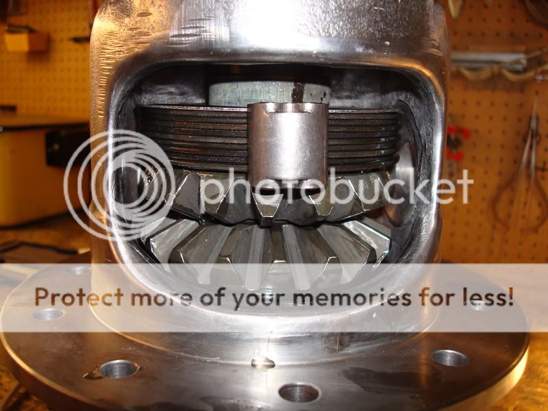
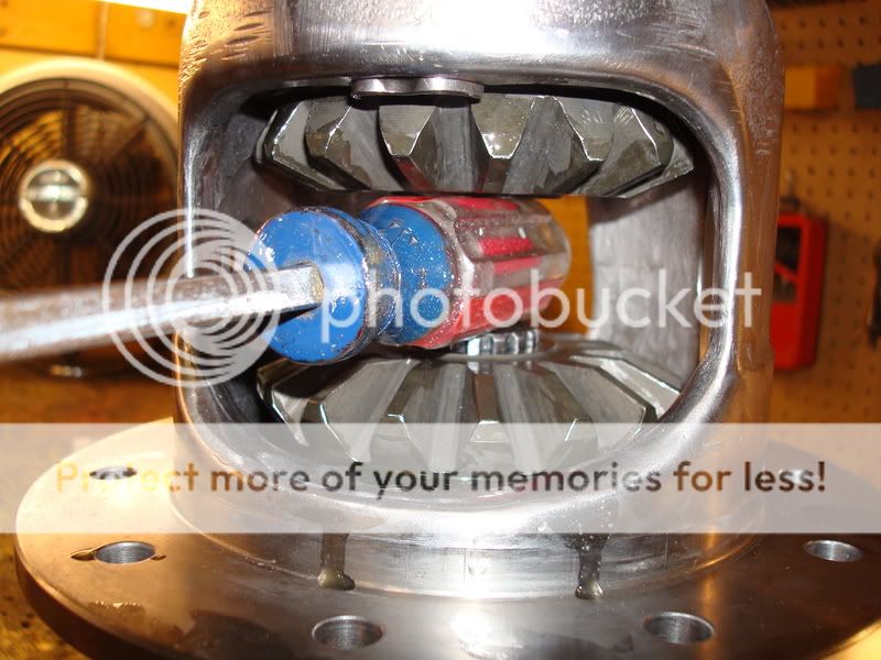
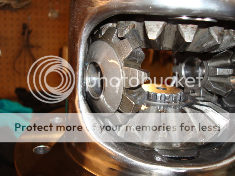
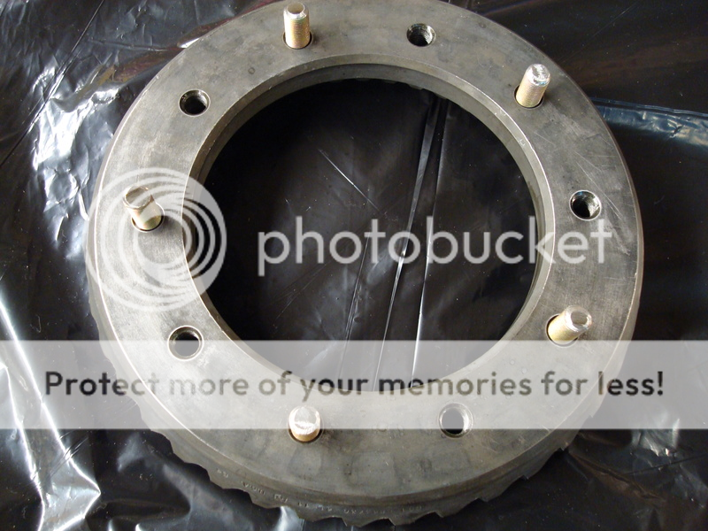
The first thing you want to do is remove the ring gear from the posi case. Take one of your old side yokes and put it in a vise, then place the posi case on top of the side yoke. It works great as a work stand. Use an impact gun to remove the ring gear bolts. The ring gear is a tight fit on the posi case, and you will need to use a hammer with a block of wood to remove it from the carrier. Work your way around the ring gear. If you are reusing you gears, be very careful – the ring gear will eventually pop loose and will fall and hit your vise. I tuned my posi unit without springs, so I wasn’t too concerned with ruining the springs. I cut them out with a dremel tool and cutting wheel. Remove the two plates that the springs were wedged between. Okay, now you are ready to remove the posi pin. PLEASE TAKE NOTE OF THIS!!!!!!!! The pin is not a press fit; it is a slip fit which is held in place with a screw/pin in the carrier. I originally thought it was a press fit, and that I had to press the pin out. So, off I went to my hydraulic press, and pressed out the large posi pin – little did I know that the pin was held in place horizontally with another long pin, and I ruined my posi case. DO NOT PRESS OUT YOUR PIN!!!! First, you need to remove pin #3 in the following diagram…
After you remove this pin, then you can slip the larger pin (#11 in the diagram) out of the housing using your finger. It is a slip fit, not a press fit, so it can be removed with little effort. I had to replace my posi case due to this one mistake – the small pin was crushed when I pressed out the larger pin, and the hole was elongated and broken…a really costly mistake on my part. Once you have removed these two items, you can remove the spider gears. Turn the posi unit by hand until the spider thrust washers drop out from behind the gears and then remove them (you won’t be reusing the thrust washers). Once you remove the spider gears (#10), then the top gear with its respected clutches and retainers will drop down and you can remove them from the carrier. All that is left to do is remove the bottom gear, which the side yoke is sitting on, and set it aside with its clutches and 2 retainers. You will not be reusing the clutches or retainers in the rebuild. However, if your spider gears are in good condition, then you may reuse them. There are two different types of gears – 17 tooth and 18 tooth. The 18 tooth gears are not as strong as the 17 tooth gears. Here is a picture from Gary regarding the difference between them (the good ones, and the ones you want, are on the right side). If you happen to have the 18 tooth gears, I’d replace them now. They are not as strong as the 17 tooth ones.
Degrease and clean the posi case, spider gears, large posi pin, and small pin/screw. Store the clutches and retainers in a zip loc bag. I also forgot to mention that the posi case sometimes has 2-3 shims on each side of the carrier – this was done by your folks at GM to pick up the slack in the case.
Carrier Inspection
You can reuse the carrier as long as it is not damaged and does not have any cracks in it. The large posi pin often elongates the machined holes in the carrier – if it is oblong, you will have to machine it for a larger pin or gears (I think Tom’s differentials does this), or replace the carrier. Look for any cracks and damage. One crack and it is toast unfortunately…don’t risk it, replace it now. All this work you’ll be doing will be for nothing if you have a bad carrier, as it will eventually go and ruin your entire diff.
Polishing the Posi Case
Now you are ready to start tuning your posi unit – it takes a lot of time to do, but it will be worth it in the end. The first thing you want to do is protect the surfaces that you don not want to polish (I used duct tape, as it is much more sticky than masking tape). Tape off the areas where the spider gear thrust washers ride – these areas are very important and you don’t want to ruin or scratch these. You will need a few tools for this job. I used a carbide burr with a dremel tool, die grinder and grinding stones, sandpaper, emery cloth and some roloc disks on a surface prep tool my dad bought me. The basic principle of this job is to remove all the stress areas from the casing – this will prolong the life of your diff, as well as make it much stronger than stock. If you look inside the casing, you’ll notice some “seams†from the casting process. You want to polish these areas as well. When you polish the windows on the carrier, you have to be careful not to continue the polishing past where the clutches ride, but you do want to carry the polishing inside the housing to the areas where the clutches don’t ride. I hope this makes sense. Here is what my new case looked like when I got it in the mail:
Here is the case after polishing (please ignore the carrier bearings, some of these pictures were taken after I decided to redo my work, and they are the best pics I have)…
After the polishing of the posi case is completed, you are ready to move onto the next step.
ARP Ring Gear Bolts
If you plan on using ARP ring gear bolts with your rebuild, now is the time to countersink the holes on you posi case. Gary touched base on this in one of his posts. Basically, what he found was there was a shoulder on the ARP bolts which prevented them from seating flat. The case I bought from Gary already had the holes countersunk, so that saved me from having to do it. A step drill might work to slightly countersink the holes too, but you'd have to ask Gary about that one. This step is mentioned in ARP’s instructions as well.
Beveling the Spider Gears
GM left a lot of slack in the original spring setup – the reason they installed the springs was to take up this slack by putting pressure on the side clutches. The clutches are designed so that they provide resistance when they are turned. By changing the spring rate in the posi unit, all you are doing is reducing side pressure on the clutches, which results in either more posi action or less posi action. They had to install springs because it was not cost effective to tune each unit by hand so there was no slack in the clutches – leaving the springs out would mean that the clutches would not drag across each other and provide no resistance. Thus, instead of the wheel turning at a different rate, it would be extremely sloppy and the spider gear tooth contact would be minimal. When both wheels are turning at the same rate, the 10 tooth spider gears prevent the clutches from turning. One spider gear wants to go left, and one spider gear wants to go right, and they lock up and turn at the same rate like a fixed axle. Thus, there really is no need for posi springs as long as you remove the slack GM left in the setup by shimming the side clutches properly. Too tight, and the clutches act just like the GM setup, and the wear on them will be excessive. Too loose and the spider gear tooth contact will be minimal and weak – and the clutches will not drag across each other providing a smooth motion. This is very time consuming, but it is worth it in the end. GM decided to try and fix their hammering issue by installing snowflake clutches to get more oil between the already stressed side clutches…now all this did was weaken them to the point that they would break.
You are going to be pulling the tolerances in very close, so you want to bevel the four posi gears’ edges. I used a dremel and a grinding stone attachment; just walk the grinding stone across the edges, don't apply any pressure (you want to break the sharp corners).
Parts
You will need to buy yourself a new set of solid clutches, a clutch shim kit, new clutch retainers and new spider thrust washers. The clutch shim kit comes with two sets of 0.010’’-0.045’’ shims in increments of 0.005’’. You will also need to get a hold of some GM posi additive for use when tuning the posi unit. Look over your crosshaft for any wear/tear. The OD of the top and bottom should be 0.747’’, and there should be no signs of the yokes wearing on the shaft. The ID of the holes in the posi case I think are 0.749’’. If it is not up to spec, replace it. Gary sells a shaft that is 0.001’’ oversize, and it is a much tighter fit. That is the one that I used during my rebuild. You also want to check the screw/pin that holds the crosshaft in place. The new pins that GM is making and selling are apparently bad quality compared to the originals - the heads break off real easy if tightened too much, and then you are screwed (no pun intended). I was lucky in getting an original GM one. I think these pins are around 18 bucks, so they aren't cheap. You want to check and see if there is a "step" in the shank of it. If there is, it should be replaced. Go back to that diagram I posted above, and look at item number 2. It is an internal ¼’’ spring washer. You will need to get a new one (I got a 100 pack from Acklands Grainger). Install it when the posi tuning is completed, as you can only use it once. DO NOT REUSE YOUR OLD ONE! I polished the screw/pin that goes through the cross shaft in the posi case using my drill as a mini lathe…
This is what an original GM Posi screw/pin looks like on the head…
Posi Tuning
Before you start tuning the posi unit, you need to make yourself another homemade tool. It is a spanner wrench for turning the unit so you can seat the clutches. I took an old lower control arm shaft I had laying around, welded a 1/2'' plate to the end and then welded two bolts to it. The two bolts fit into two of the holes on the posi case, which allows you to turn it with extra leverage. I coated the end of it in some black rubber I had laying around - it prevented me from accidentally scratching my posi case when I was working on it.
After you make your new homemade tool, you are ready to start the posi tuning procedure. I really had to climb into Gary’s head and understand what he was explaining to me as to what he feels when he tunes a posi unit. You wouldn’t believe how many questions I asked him – I’m OCD when it comes to stuff like this.
I clean everything with brake cleaner and compressed air. The next step is to sort out the clutches. They are stamped differently on each side. If you draw you fingernail around the edges, you'll immediately know which side has the deeper stamping. Take a sharpie and put a small "d" on the deeper face so you don't have to keep checking when assembling. The marker will eventually wear off from the oil, but it will keep you organized. I asked Gary as to whether it mattered which way the two clutch packs faced (do all the deep stampings for both sides need to face to the left, or to the right). He said it didn't matter, but you need to keep the deep faces facing in one direction for each clutch pack. Lay all your parts onto a clean rag - once again, this will keep you organized. Oil the clutches with GM posi additive.
Alright, here is where all the patience on this project comes in - figuring out which size shim is required to set up the posi case. Here is a shot of all the shims that came in Gary's kit...