I used several software dyno programs,most work reasonably well and you might be surprised at the accuracy most of the time!
Ive used mostly ENGINE ANALYZER PRO, I purchased when it first came out,
and altho EA PRO is far more detailed in its answers and it even suggested changes, its useful but its also a P.I.T.A. to use as it requires a great deal of precise detail to make its calculations
http://www.auto-ware.com/software/eap/eap.htm
the DD2000 software
this ones far easier to use, but not as accurte
http://www.proracingsim.com/desktopdyno.htm
gets surprizingly close to the dyno results most of the time IF you put in the correct info for it to work with.
naturally ...Garbage- Info- in-Garbage-info Out applies
cam install info
I think most experienced guys have two or three degree wheels for that very reason,
(that the larger size is tough to fit in an engine compartment on an installed engine)
I bought these
http://www.summitracing.com/parts/mor-62191/overview/

http://www.summitracing.com/parts/pro-66791/overview/
http://www.summitracing.com/parts/pro-66830/overview/
http://www.summitracing.com/parts/cca-4927/overview/
JUST TRYING TO FIND TDC??
you FIRST disconnect the battery and use a ratchet to spin the engine slowly by hand , useing the damper bolt and a 5/8 socket after removing the spark plugs, chalking the wheels and putting the cars trans in neutral
ways to turn over the engine WITHOUT the starter
theres large bolts for your ballancer
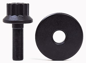
theres crank sockets
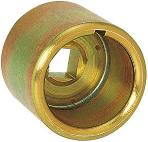
Crankshaft Socket Tool For turning AND MOUNTING Degree Wheels

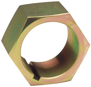
CRANK NUTS
crank rotaters
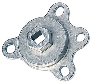
flywheel turning tools

http://www.jegs.com/i/JEGS/555/80743/10002/-1
finding TDC
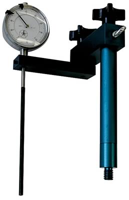
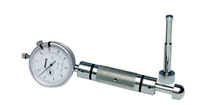
youll need a piston stop and degree wheel to be exact
but thats not 100% required unless you want it to work correctly???
http://store.summitracing.com/partdetail.asp?autofilter=1&part=CRN-99412-1&N=700+115&autoview=sku
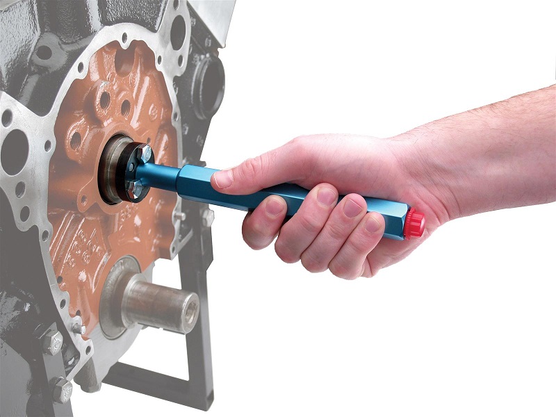
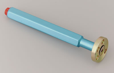
use of a camshaft install handle generally reduces the chances of damaged cam bearings
read
http://www.2quicknovas.com/happyTDC.html
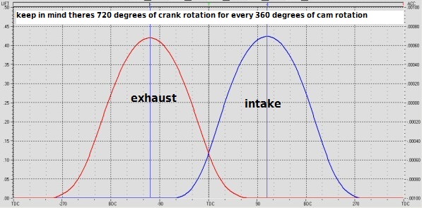
btw you might want to verify this next time you degree in a cam, so that next time you use dyno simulation software you enter the data correctly,
theres a hugely popular myth that simply is wrong, if your using a dyno simulation software program, ...,
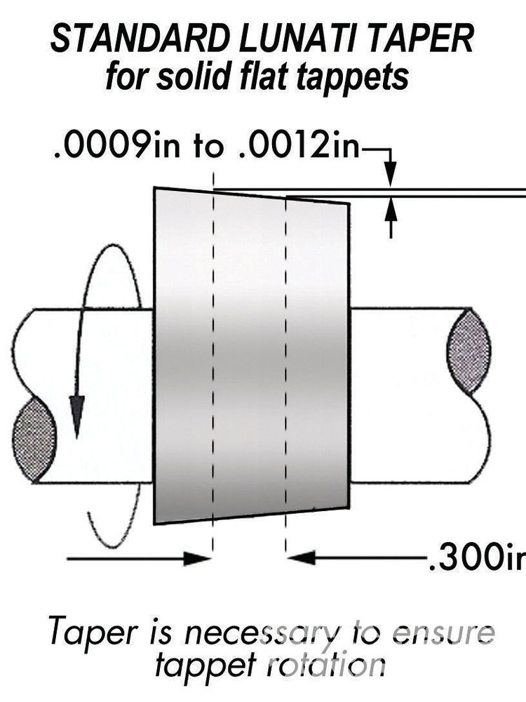
no you don,t reduce or subtract the lift of the cam lobe by the lash, clearance,
when calculating the valve lift of a solid lifter cam,
and you don,t subtract the lifter seat movement on a hydraulic cam,
as that change in lift rate is ALL absorbed or removed on the cam lobes feed ramp
the lifter still lift,s the valve to the full lift.
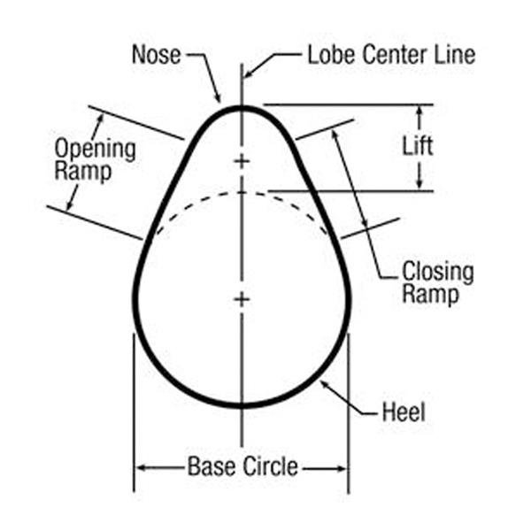
measure the difference the edge of the lifter moves from the time the lifter is on the cams base circle to peak lift than set the lifter back on the base circle again and set the dial indicator to zero with a .0024 feeler gauge between the lifter and dial indicator, and re- measure total lift.
nothing changes on that peak lift , its change is absorbed by the cam lobes feed ramp, the rate of lift per degree of rotation is very slightly delayed , not reduced
the valve lash is clearance it does NOT add or subtract from the lift , if you have a solid lift cam rated at lets say .520 lift with a 1.5 :1 ratio rocker, changing the lash clearance,will effect how it runs and when the valve comes off the valve seat by a degree or two ,but unless you add a good deal more than the .024 specified lash clearance or so thats listed, on the spec card, for lash clearance, it has ALMOST ZERO EFFECT on total lift, and a change to a 1.6:1 ratio will effectively increase the lift to .554
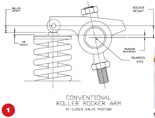
the lifter starts on the base circle, the lobe passing under the lifter causes the lifter and pushrod to move up away from the base circle too peak lobe lift, the rocker ratio increases that lift at the valve through the leverage it provides working through the pivot point on the ball or axle inside the rocker centered on the rocker stud,
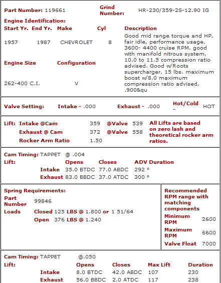
heres your typical cam spec card this one happens to be the crane cam I selected for my corvette
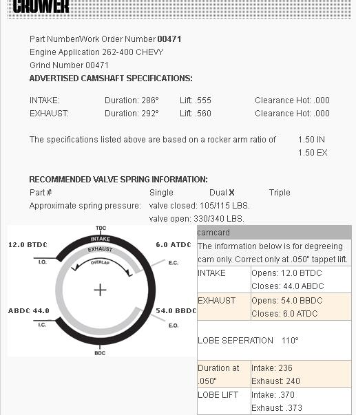
heres the spec card from the t-buckets 406 sbc
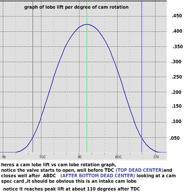
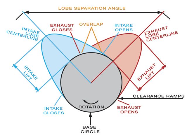
if you were to graph in the lash slack the valve lift would start a degree or so later and end a degree or so earlier,
but the total lift would remain constant as the distance the lifter travel in the blocks lifter bore as the cam lobe rotates under it,
from the base circle to the peak lift remains consistent
http://www.summitracing.com/parts/mor-62191/overview/
http://www.summitracing.com/parts/pro-66791/overview/
http://www.summitracing.com/parts/pro-66830/overview/
http://www.summitracing.com/parts/cca-4927/overview/
theres very useful links and info sources below
http://racingdownloads.com/
http://www.performancetrends.com/EA30.htm
http://www.performancetrends.com/index.html
http://www.motionsoftware.com/
http://speedtalk.com/v-dyno-racing-software.html
http://www.auto-ware.com/software/es/eswin.htm
http://www.hotrodsandclassics.net/Virtu ... or.bac.htm
Ive used mostly ENGINE ANALYZER PRO, I purchased when it first came out,
and altho EA PRO is far more detailed in its answers and it even suggested changes, its useful but its also a P.I.T.A. to use as it requires a great deal of precise detail to make its calculations
http://www.auto-ware.com/software/eap/eap.htm
the DD2000 software
this ones far easier to use, but not as accurte
http://www.proracingsim.com/desktopdyno.htm
gets surprizingly close to the dyno results most of the time IF you put in the correct info for it to work with.
naturally ...Garbage- Info- in-Garbage-info Out applies
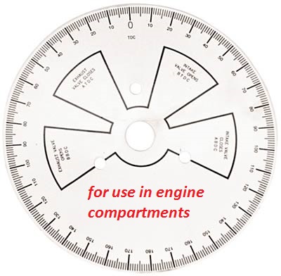
cam install info
I think most experienced guys have two or three degree wheels for that very reason,
(that the larger size is tough to fit in an engine compartment on an installed engine)
I bought these
http://www.summitracing.com/parts/mor-62191/overview/
http://www.summitracing.com/parts/pro-66791/overview/
http://www.summitracing.com/parts/pro-66830/overview/
http://www.summitracing.com/parts/cca-4927/overview/
JUST TRYING TO FIND TDC??
you FIRST disconnect the battery and use a ratchet to spin the engine slowly by hand , useing the damper bolt and a 5/8 socket after removing the spark plugs, chalking the wheels and putting the cars trans in neutral
ways to turn over the engine WITHOUT the starter
theres large bolts for your ballancer
theres crank sockets
Crankshaft Socket Tool For turning AND MOUNTING Degree Wheels
CRANK NUTS
crank rotaters
flywheel turning tools
http://www.jegs.com/i/JEGS/555/80743/10002/-1
finding TDC
youll need a piston stop and degree wheel to be exact
but thats not 100% required unless you want it to work correctly???
http://store.summitracing.com/partdetail.asp?autofilter=1&part=CRN-99412-1&N=700+115&autoview=sku
use of a camshaft install handle generally reduces the chances of damaged cam bearings
read
http://www.2quicknovas.com/happyTDC.html
btw you might want to verify this next time you degree in a cam, so that next time you use dyno simulation software you enter the data correctly,
theres a hugely popular myth that simply is wrong, if your using a dyno simulation software program, ...,
no you don,t reduce or subtract the lift of the cam lobe by the lash, clearance,
when calculating the valve lift of a solid lifter cam,
and you don,t subtract the lifter seat movement on a hydraulic cam,
as that change in lift rate is ALL absorbed or removed on the cam lobes feed ramp
the lifter still lift,s the valve to the full lift.
measure the difference the edge of the lifter moves from the time the lifter is on the cams base circle to peak lift than set the lifter back on the base circle again and set the dial indicator to zero with a .0024 feeler gauge between the lifter and dial indicator, and re- measure total lift.
nothing changes on that peak lift , its change is absorbed by the cam lobes feed ramp, the rate of lift per degree of rotation is very slightly delayed , not reduced
the valve lash is clearance it does NOT add or subtract from the lift , if you have a solid lift cam rated at lets say .520 lift with a 1.5 :1 ratio rocker, changing the lash clearance,will effect how it runs and when the valve comes off the valve seat by a degree or two ,but unless you add a good deal more than the .024 specified lash clearance or so thats listed, on the spec card, for lash clearance, it has ALMOST ZERO EFFECT on total lift, and a change to a 1.6:1 ratio will effectively increase the lift to .554
the lifter starts on the base circle, the lobe passing under the lifter causes the lifter and pushrod to move up away from the base circle too peak lobe lift, the rocker ratio increases that lift at the valve through the leverage it provides working through the pivot point on the ball or axle inside the rocker centered on the rocker stud,
heres your typical cam spec card this one happens to be the crane cam I selected for my corvette
heres the spec card from the t-buckets 406 sbc
if you were to graph in the lash slack the valve lift would start a degree or so later and end a degree or so earlier,
but the total lift would remain constant as the distance the lifter travel in the blocks lifter bore as the cam lobe rotates under it,
from the base circle to the peak lift remains consistent
http://www.summitracing.com/parts/mor-62191/overview/
http://www.summitracing.com/parts/pro-66791/overview/
http://www.summitracing.com/parts/pro-66830/overview/
http://www.summitracing.com/parts/cca-4927/overview/
theres very useful links and info sources below
http://racingdownloads.com/
http://www.performancetrends.com/EA30.htm
http://www.performancetrends.com/index.html
http://www.motionsoftware.com/
http://speedtalk.com/v-dyno-racing-software.html
http://www.auto-ware.com/software/es/eswin.htm
http://www.hotrodsandclassics.net/Virtu ... or.bac.htm
Last edited by a moderator: