do strokers increase compression ratio?

grumpyvette

Administrator
Staff member
"IM building a 496 stroker from my 454 engine in the corvette, I read somewhere that the 4.25 stroke of this engine will boost the compression a little more than the standard 4.00 stroke. Is that true? I thought that if I used the 10-1 pistons that are MADE to be used with the 6.385 rods, my compression would be the stated 10-1. Any thoughts? "

read this also

viewtopic.php?f=44&t=38&p=46#p46

http://kb-silvolite.com/article.php?action=read&A_id=36

first Id point out that your comparing apples & oranges too some extent, if you had flat top pistons designed for either engine with the came deck height, valve notches,etc, but the correct pin height for the application, or for that matter any pistons with identical dome displacement, and you use the same cylinder heads with the same combustion chamber size, increasing the stroke will increase the compression simply because youve increased the sweep voluum between bdc and tdc, play with this calc, change only the stroke on any combo and look over the results

http://www.csgnetwork.com/compcalc.html

now once you understand that approach, BUT you need to understand that the compression and dome height IS by design DIFFERENT on the 10:1 pistons for a 4" stroke and a 4.25" stroke piston designed to have 10:1 compression.
both will have approximately 10:1 cpr in thier intended application, but the pin height, piston dome cc ETC. will differ a great deal, if the compression ratio is designed to stay at the same 10:1 ratio


now it may help if you play with these calculators (below)

http://www.projectpontiac.com/ppsite/co ... iew/16/30/

http://kb-silvolite.com/calc.php?action=piston_comp

http://kb-silvolite.com/calc.php?action=deck

http://kb-silvolite.com/calc.php?action=piston

http://kb-silvolite.com/calc.php?action=comp2

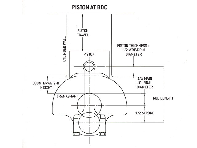
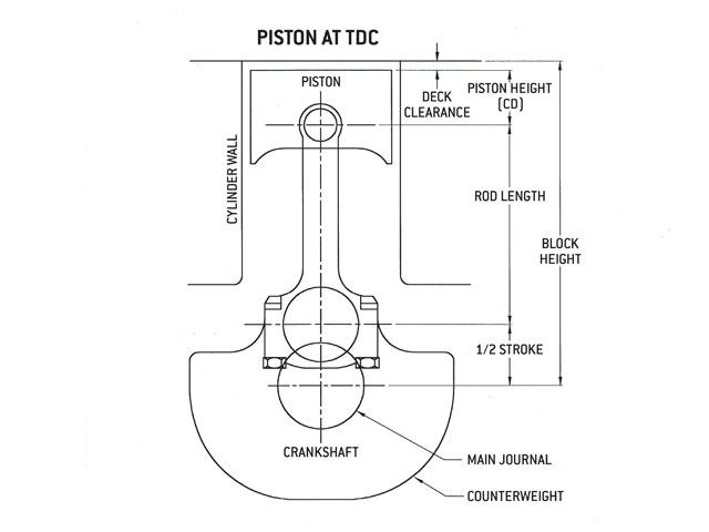
keep in mind the blocks deck and crank centerline stay constant

if the blocks deck is 9.8" from the crank centerline and you have a 4.0" stroke with a 6.135" rod youll need a 1.665" pin height in the piston
if the blocks deck is 9.8" from the crank centerline and you have a 4.25" stroke with a 6.385" rod youll need a 1.29" pin height in the piston


http://www.hotrod.com/articles/1206phr-383ci-small-block-chevy/

http://www.superchevy.com/how-to/76178-chevrolet-ht-383-engine/

http://www.enginelabs.com/news/dyno-video-qmp-builds-500-horse-383-stroker/

http://www.chevyhardcore.com/tech-stories/engine/building-the-little-383-small-block-that-could/

http://royalpurpleconsumer.com/wp-c...-block-in-six-easy-steps-hot-rod-magazine.pdf
 
Last edited by a moderator:
this is referring to "static" compression correct ???
yes, but here is an old post explaining the difference

its obvious some of the guys on this site need to understand the differance between static and dynamic compression ratios, and that's understandable as its a difficult concept to grasp at first
but you need to understand it before selecting a combos components

the difference between STATIC COMPRESSION RATIO AND DYNAMIC COMPRESSION RATIO is where the piston is in the cylinder when the valves close and the piston can actually start compressing the REMAINING VOLUME IN THE CYLINDER VS the STATIC COMPRESSION THAT ASSUMES THE PISTON STARTS COMPRESSING THE INSTANT IT LEAVES BOTTOM DEAD CENTER AND STARTS UPWARD ON THE COMPRESSION STROKE!


let me try and explain, [color:"red"] the short version is that the PISTON COMPRESSES NOTHING until BOTH VALVES ARE CLOSED, .......that's the only compression ratio that matters,.... since its the only compression ratio the engine ever sees.[/color]

static compression is simply the difference between the cylinder volume at BOTTOM DEAD CENTER(BDC) and its compressed volume at TOP DEAD CENTER (TDC), into the combustion chambers,... dynamic compression takes into account that on the pistons upward compression stroke the valves have not yet closed and nothing gets compressed by the piston until they do, that of course depends on the cam and rockers, pistons and connecting rods, the cylinder volume, the rod/stroke ratio, ETC.,used, in the combo, and the rpm levels to some extent


BTW, ALUMINUM HEADS can usually operate at a higher dynamic compression simply because ALUMINUM releases heat to the coolant much faster than iron, its the lower heat levels that remain in the cylinder that help prevent detonation..when you increase the dynamic compression the heat levels in the heads combustion chamber rise , the difference in the RATE heat leaves the cylinder allows a slightly higher dynamic compression level from aluminum before the same HEAT levels are REACHED & MAINTAINED in the combustion chambers


here is a calculator for static cpr, which you need to figure first

let me point out a few things
first look at this chart

http://www.iskycams.com/ART/techinfo/ncrank1.pdf

then lets assume your 350 sbc engine has a static compression ratio of 11:1 but you've installed this cam

http://dab7.cranecams.com/SpecCard/DisplayCatalogCard.asp?PN=114681&B1=Display+Card

looking at the cam specs we see that the effective stroke is not the 3.48" that the static compression ratio is measured from ,at BDC, BUT from about 2.6 inches from tdc where the valves close as the piston moves upward, so your true working compression is closer to 8.1:1 NOT 11:1

heres a longer more detailed explanation and access to the software to figure dynamic cpr with the cam your useing in your engine

http://cochise.uia.net/pkelley2/DynamicCR.html

http://www.diamondracing.net/cocalc.htm

heres some different calculators

http://www.kb-silvolite.com/calc.php?action=comp2

http://www.wallaceracing.com/dynamic-cr.php

http://www.smokemup.com/auto_math/compression_ratio.php

http://not2fast.wryday.com/turbo/compression/cranking_pressure.shtml
average the results

keep in mind that you can easily run a static compression of 11:1 with aluminum heads if you keep the cam timing in a range so that the DYNAMIC COMPRESSION is CLOSE TO 8:1
take the time to understand the concept,it VERY IMPORTANT


read this

http://www.diamondracing.net/cocalc.htm


http://victorylibrary.com/mopar/cam-tech.htm

http://victorylibrary.com/mopar/otto-c.htm

http://victorylibrary.com/mopar/cam-tech-c.htm

http://kb-silvolite.com/article.php?acti...3117842f4eb4c49

http://victorylibrary.com/mopar/rod-tech-c.htm

http://victorylibrary.com/mopar/piston_position-c.htm

http://www.iskycams.com/techtips.html#2003

http://victorylibrary.com/mopar/rod-tech.htm

http://www.zhome.com/ZCMnL/PICS/detonation/detonation.html

http://www.chevytalk.org/threads/showfla...true#Post397334

if cams are a mystery please take the time to read these, it will get you a good start


http://www.wighat.com/fcr3/confusion.htm

http://www.chevyhiperformance.com/techarticles/95298/

http://www.idavette.net/hib/camcon.htm

http://www.centuryperformance.com/valveadjustment.htm

http://www.totalengineairflow.com/tech/valvelashing.htm

http://www.chevytalk.com/tech/engine/Cam_Selection.html

http://www.chevytalk.com/tech/101/Cam_Theory.html

http://www.babcox.com/editorial/ar/ar119736.htm


http://www.symuli.com/vw/camp1.html

http://www.symuli.com/vw/camp2.html

http://home.wxs.nl/~meine119/tech/camqa.html

http://www.chevytalk.org/threads/showfla...true#Post200511

http://www.crower.com/misc/valve_timing_chart.html

http://www.speedomotive.com/Building%20Tips.htm

]

http://chevyhiperformance.com/techarticles/94138/

http://www.aera.org/Members/EngineTech/engine.htm

http://www.zhome.com/ZCMnL/PICS/detonation/detonation.html
 
pistonatbdc.jpg

pistonat%20tdc.jpg


this gives you some idea as to the piston skirt and counter weights on the crank clearance issue that many guys can,t easily visualize on a stroker, one reason the longer 6" rods on a SBC stroker and 6.385"-6.8" length rods are used on some stroker BBC combos

OK you've decked the block .010 during the block machining process , how did that change the compression?
pistonat%20tdc.jpg

if you decked the block .010 you've effectively moved the piston .010 closer to the cylinder heads unless the head gasket is selected to be .010 thicker to compensate
I don,t know the bore diam. but lets assume in a calculation its 4" bore

cutting a deck on a block and not compensating with a thicker head gasket on that 4" bore had about a 2 cc reduction in the total area over the piston being compressed, into the combustion chamber above it, simply because the area of the bore times the depth of the cylinder results in that volume
formula

bore radius sq x 3.147 x .010 x 16.39(changes cubic inches to CCs)

(reference you need TO COMPLETE THE CALCS)

http://www.hotrod.com/techarticles/engine/how_to_calculate_compression_ratio/index.html

http://www.circletrack.com/techarticles/ctrp_0505_calculating_engine_compression/index.html

http://garage.grumpysperformance.com/index.php?threads/383-build-for-a-friend.14273/

http://forum.grumpysperformance.com/viewtopic.php?f=86&t=1330

http://forum.grumpysperformance.com/viewtopic.php?f=52&t=727

http://forum.grumpysperformance.com/viewtopic.php?f=53&t=726
 
Last edited by a moderator:
OK youve decked the block .010 durring the block machining process , how did that change the compression?
if you decked the block .010 youve effectively moved the piston .010 closer to the cylinder heads unless the head gasket is selected to be .010 thicker to compensate
I don,t know the bore dia. but lets assume in a calculation its 4" bore

cutting a deck on a block and not compensating with a thicker head gasket on that 4" bore had about a 2 cc reduction in the total area over the piston being compressed, into the combustion chamber above it, simply because the area of the bore times the depth of the cylinder results in that volume
formula

bore radias sq x 3.147 x .010 x 16.39(changes cubic inches to CCs)

(referance you need TO COMPLETE THE CALCS)

http://www.hotrod.com/techarticles/engine/how_to_calculate_compression_ratio/index.html

http://www.circletrack.com/techarticles/ctrp_0505_calculating_engine_compression/index.html

http://forum.grumpysperformance.com/viewtopic.php?f=86&t=1330

http://forum.grumpysperformance.com/viewtopic.php?f=52&t=727
EXAMPLE pay attention to the bore stroke ratios, a 307 with its greater bore and shorter stroke , and slightly ;larger displacement and less valve shrouding should ALWAYS show a slight advantage in performance over a 305 as a basic engine

Chevy V8 bore & stroke chart

Post by RebStew on Fri 08 Feb 2008, 3:28 pm
CHEVY SMALLBLOCK V-8 BORE AND STROKE


262 = 3.671" x 3.10" (Gen. I, 5.7" rod)
265 = 3.750" x 3.00" ('55-'57 Gen.I, 5.7" rod)
265 = 3.750" x 3.00" ('94-'96 Gen.II, 4.3 liter V-8 "L99", 5.94" rod)
267 = 3.500" x 3.48" (Gen.I, 5.7" rod)
283 = 3.875" x 3.00" (Gen.I, 5.7" rod)
293 = 3.779" x 3.27" ('99-later, Gen.III, "LR4" 4.8 Liter Vortec, 6.278" rod)
302 = 4.000" x 3.00" (Gen.I, 5.7" rod)
305 = 3.736" x 3.48" (Gen.I, 5.7" rod)
307 = 3.875" x 3.25" (Gen.I, 5.7" rod)

325 = 3.779" x 3.622" ('99-later, Gen.III, "LM7", "LS4 front wheel drive V-8" 5.3 Liter Vortec, 6.098" rod)
327 = 4.000" x 3.25" (Gen.I, 5.7" rod)
345 = 3.893" x 3.622" ('97-later, Gen.III, "LS1", 6.098" rod)
350 = 4.000" x 3.48" (Gen.I, 5.7" rod)
350 = 4.000" x 3.48" ('96-'01, Gen. I, Vortec, 5.7" rod)
350 = 3.900" x 3.66" ('89-'95, "LT5", in "ZR1" Corvette 32-valve DOHC, 5.74" rod)
364 = 4.000" x 3.622" ('99-later, Gen.III, "LS2", "LQ4" 6.0 Liter Vortec, 6.098" rod)
376 = 4.065" x 3.622" (2007-later, Gen. IV, "L92", Cadillac Escalade, GMC Yukon)
383 = 4.000" x 3.80" ('00, "HT 383", Gen.I truck crate motor, 5.7" rod)
400 = 4.125" x 3.75" (Gen.I, 5.565" rod)
427 = 4.125" x 4.00" (2006 Gen.IV, LS7 SBC, titanium rods)

Two common, non-factory smallblock combinations:

377 = 4.155" x 3.48" (5.7" or 6.00" rod)
400 block and a 350 crank with "spacer" main bearings
383 = 4.030" x 3.75" (5.565" or 5.7" or 6.0" rod)
350 block and a 400 crank, main bearing crank journals
cut to 350 size


--------------------------------------------------------------------------------

CHEVY BIG BLOCK V-8 BORE AND STROKE


366T = 3.935" x 3.76"
396 = 4.096" x 3.76"
402 = 4.125" x 3.76"
427 = 4.250" x 3.76"
427T = 4.250" x 3.76"
454 = 4.250" x 4.00"
496 = 4.250" x 4.37" (2001 Vortec 8100, 8.1 liter)
502 = 4.466" x 4.00"
572T = 4.560" x 4.375" (2003 "ZZ572" crate motors)
http://forum.grumpysperformance.com/viewtopic.php?f=53&t=726
engbal51.gif

y David Reher, Reher-Morrison Racing Engines

“An engine produces peak torque at the rpm where it is most efficient.”

Recently I’ve had several conversations with racers who wanted to build engines with long crankshaft strokes and small cylinder bores. When I questioned them about their preference for long-stroke/small-bore engines, the common answer was that this combination makes more torque. Unfortunately that assertion doesn’t match up with my experience in building drag racing engines.

My subject is racing engines, not street motors, so I’m not concerned with torque at 2,000 rpm. In my view, if you are building an engine for maximum output at a specific displacement, such as a Comp eliminator motor, then the bores should be as big as possible and the stroke as short as possible. If you’re building an engine that’s not restricted in size, such as a heads-up Super eliminator or Quick 16 motor, then big bores are an absolute performance bargain.

I know that there are drag racers who are successful with small-bore/long-stroke engines. And I know that countless magazine articles have been written about “torque monster” motors. But before readers fire off angry e-mails to National DRAGSTER about Reher’s rantings on the back page, allow me to explain my observations on the bore vs. stroke debate.

In mechanical terms, the definition of torque is the force acting on an object that causes that object to rotate. In an internal combustion engine, the pressure produced by expanding gases acts through the pistons and connecting rods to push against the crankshaft, producing torque. The mechanical leverage is greatest at the point when the connecting rod is perpendicular to its respective crank throw; depending on the geometry of the crank, piston and rod, this typically occurs when the piston is about 80 degrees after top dead center (ATDC).

So if torque is what accelerates a race car, why don’t we use engines with 2-inch diameter cylinder bores and 6-inch long crankshaft strokes? Obviously there are other factors involved.

The first consideration is that the cylinder pressure produced by the expanding gases reaches its peak shortly after combustion begins, when the volume above the piston is still relatively small and the lever arm created by the piston, rod and crank pin is an acute angle of less than 90 degrees. Peak cylinder pressure occurs at approximately 30 degrees ATDC, and drops dramatically by the time that the rod has its maximum leverage against the crank arm. Consequently the mechanical torque advantage of a long stroke is significantly diminished by the reduced force that’s pushing against the piston when the leverage of a long crankshaft stroke is greatest.

An engine produces peak torque at the rpm where it is most efficient. Efficiency is the result of many factors, including airflow, combustion, and parasitic losses such as friction and windage. Comparing two engines with the same displacement, a long-stroke/small-bore combination is simply less efficient than a short-stroke/big-bore combination on several counts.

Big bores promote better breathing. If you compare cylinder head airflow on a small-bore test fixture and on a large-bore fixture, the bigger bore will almost invariably improve airflow due to less valve shrouding. If the goal is maximum performance, the larger bore diameter allows the installation of larger valves, which further improve power.

A short crankshaft stroke reduces parasitic losses. Ring drag is the major source of internal friction. With a shorter stroke, the pistons don’t travel as far with every revolution. The crankshaft assembly also rotates in a smaller arc so the windage is reduced. In a wet-sump engine, a shorter stroke also cuts down on oil pressure problems caused by windage and oil aeration.

The big-block Chevrolet V-8 is an example of an engine that responds positively to increases in bore diameter. The GM engineers who designed the big-block knew that its splayed valves needed room to breath; that’s why the factory machined notches in the tops of the cylinder bores on high-performance blocks. When Chevy went Can-Am racing back in the ’60s, special blocks were produced with 4.440-inch bores instead of the standard 4.250-inch diameter cylinders. There’s been a steady progression in bore diameters ever since. We’re now using 4.700-inch bores in NHRA Pro Stock, and even bigger bores in unrestricted engines.

Racers are no longer limited to production castings and the relatively small cylinder bore diameters that they dictated. Today’s aftermarket blocks are manufactured with better materials and thicker cylinder walls that make big-bore engines affordable and reliable. A sportsman drag racer can enjoy the benefits of big cylinder bores at no extra cost: a set of pistons for 4.500-inch, 4.600-inch or 4.625-inch cylinders cost virtually the same. For my money, the bigger bore is a bargain. The customer not only gets more cubic inches for the same price, but also gets better performance because the larger bores improve airflow. A big-bore engine delivers more bang for the buck.

Big bores aren’t just for big-blocks. Many aftermarket Chevy small-block V-8s now have siamesed cylinder walls that will easily accommodate 4.185-inch cylinder bores. There’s simply no reason to build a 383-cubic-inch small-block with a 4-inch bore block when you can have a 406 or 412-cubic-inch small-block for about the same money.

There are much more cost-effective ways to tailor an engine’s torque curve than to use a long stroke crank and small bore block. The intake manifold, cylinder head runner volume, and camshaft timing all have a much more significant impact on the torque curve than the stroke – and are much easier and less expensive to change
 
Back
Top