adam said:So I decided to buy a couple of worthless old 283s to learn how to build engines. If I acquire the appropriate skills, I'm going to build a torquey 383 out of the anemic '77 350 in my C30. It tows cars, but it doesn't exactly set the road on fire, if you know what I mean.
Anyway, I bought two 283 short motors, a pair of heads, intake and carb, and a few other things for $200 for the purpose of learning to build motors. The better of the two short blocks is + .040 and has a minimal lip on the bores. I pulled the pistons today though, and I found that one big end journal on the crank has a pretty decent set of scores on it. I can feel it easily with my finger, and the bearing for that rod was pretty scratched-up looking. The other 7 rod journals are good.
So, if I reassemble this beast with the same bearings, no crank grind, just clean the parts and put it together, how bad will it be? Will it last 10k miles? 10 miles? Any engine builders there got any input?
Thanks in advance! Adam from Melbourne, Australia.
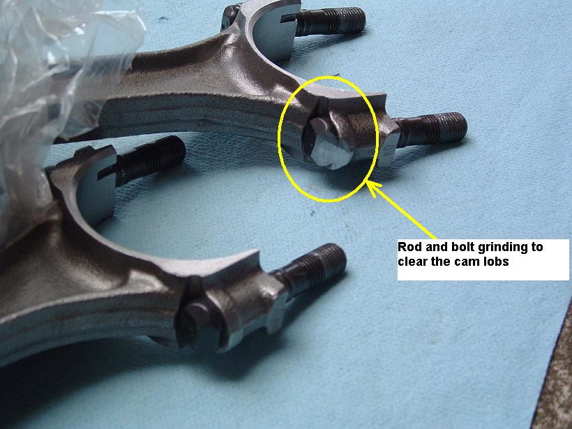
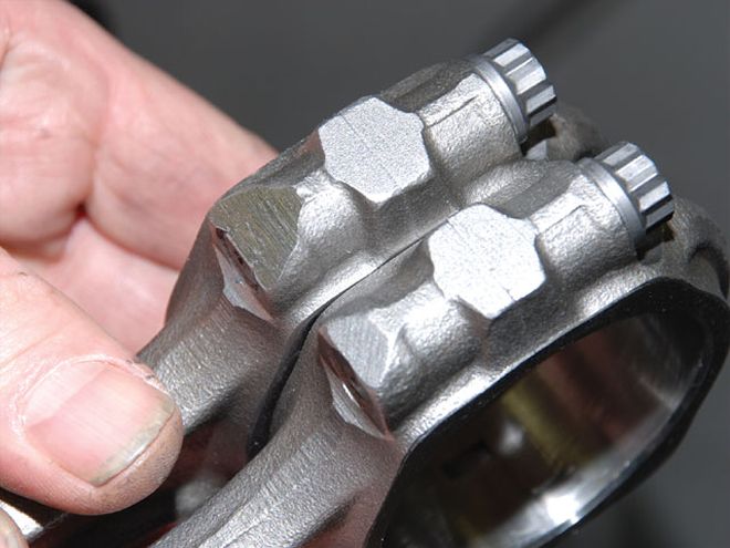
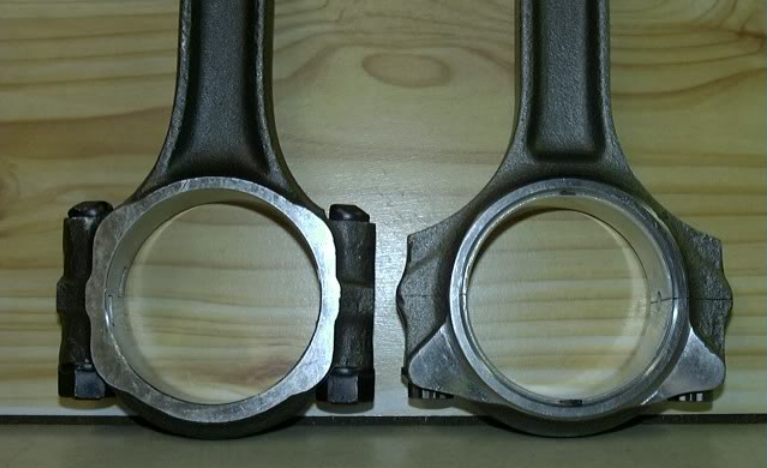
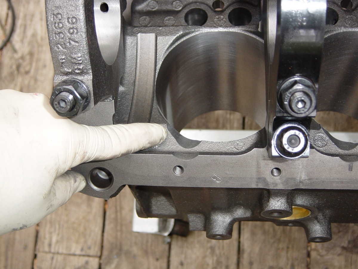
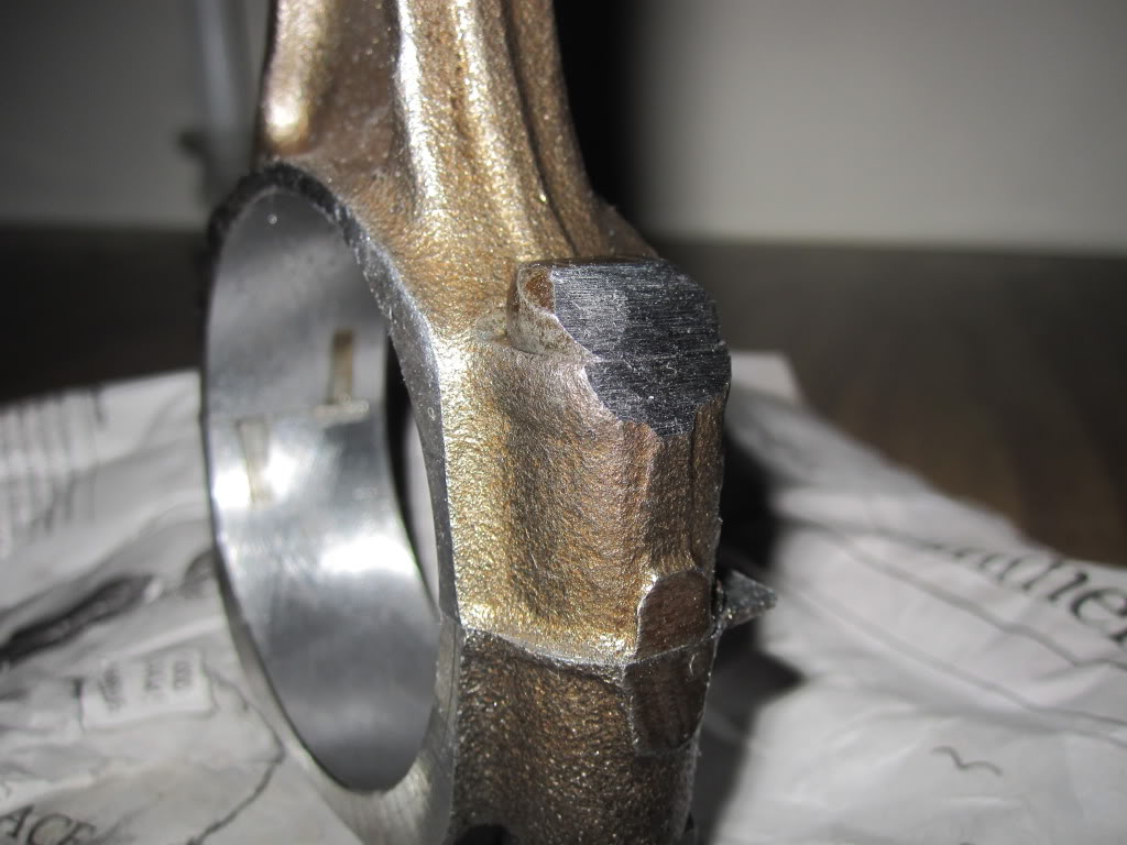
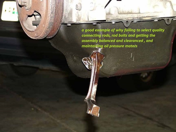
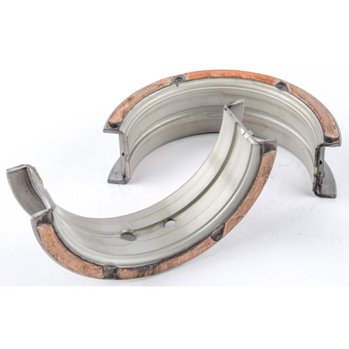
rods that use bolts with nuts like pictured below will be weakened if excessively clearance ground
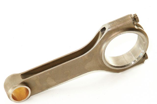
stroker profile rods offer more clearance to cam lobes, and yes the stroker clearanced profile rods are available in both (h) and (I ) beam designs
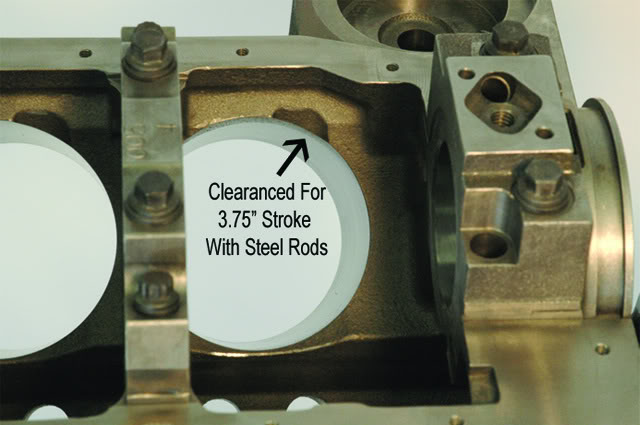
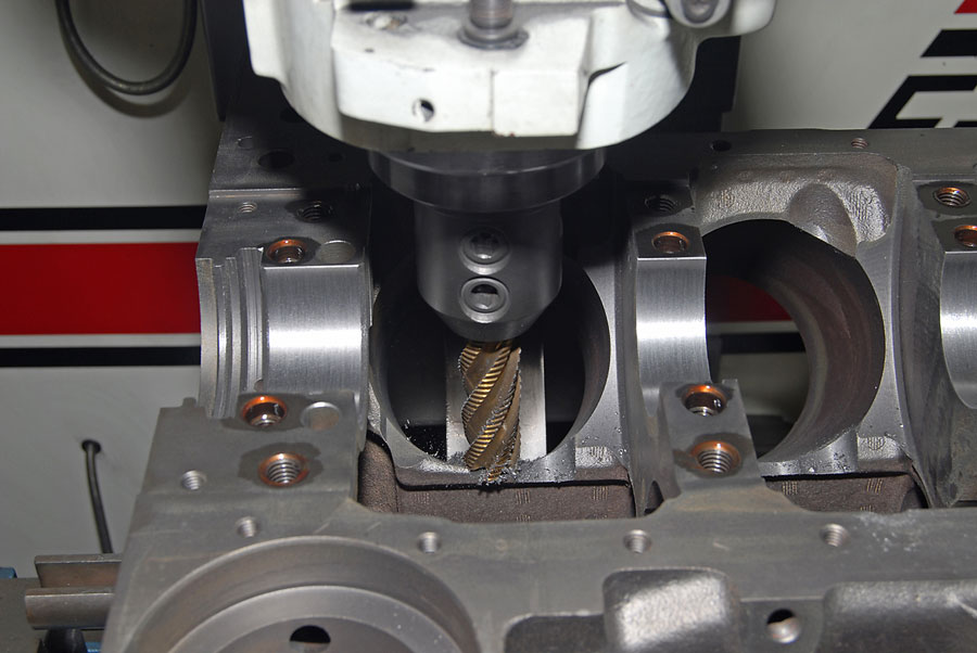
generally its a minor easily done clearance job
the cam rotates while indexed by the timing chain at 1/2 crank shaft speed , there are connecting rods designed to provide additional clearance.
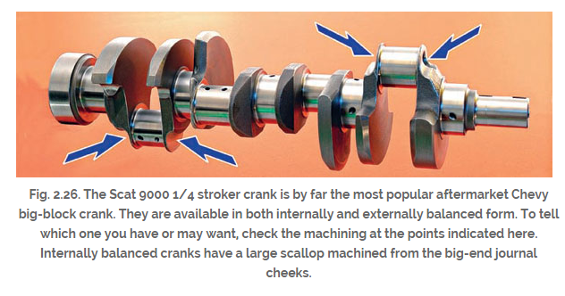
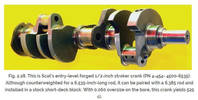
http://www.scatcrankshafts.com/index.htm
don,t forget to verify the cam to connecting rod clearances
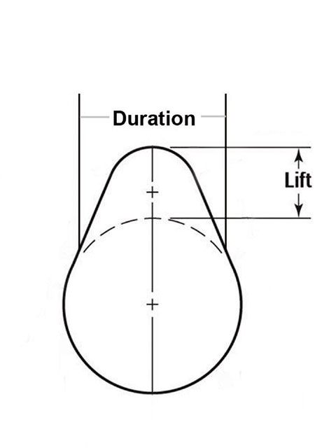
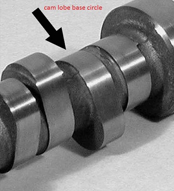
a cams VALVE LIFT is determined by the DISTANCE the lifter moves as the cam rotates under the lifter base as it moves from the cam lobe base circle
(the closest the lifter comes to the cams center line)
up to the cam lobes ramp to the lobes peak,
(the furthest the lifter up off or from the cams center line)
- https://www.harborfreight.com/air-die-grinder-with-3-inch-extension-99698.html
this model die grinder is surprisingly good quality for a disposable throw away die grinder,and usually last for more than two cylinder heads, its a true bargain, if it lasts only for two! don,t even think about use of the hard stone grinding bits they shatter and are cheap crap, get real carbide burrs
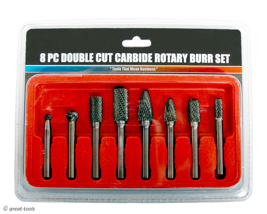
http://www.mcsdepot.com/browseproducts/ ... REACH.HTML
be sure you order the correct matched shank diam. burrs
- https://www.harborfreight.com/air-die-grinder-with-3-inch-extension-99698.html
your cams lift, is the result of the lifter movement, or distance it travels from the cams base circle, where the valves seated, to the point in the cams rotation where the lifters moved along the ramp surface fully up on the nose of the cam lobe where the valves at full lift.
example
lets say in this case we compare two imaginary cams
a standard cams base circle is 1.125" and
your cams running on a .900 base circle
both cams have a .560 valve lift and run with 1.5:1 rockers
so both cams will need to move the lifter .374"
that means the standard cam lobe will be 1.125"+.374" or 1.499" from the cams base to the cam lobe nose
that means the small base cam lobe will be .900"+.374" or 1.274" from the cams base to the cam lobe nose
which is significantly smaller,
small base circle cams are generally only used when connecting rod clearance necessitates there use
the BASE CIRCLE IS NEVER A CLEARANCE ISSUE, its the cam LOBES that can potentially contact the edge of the connecting rods or bolts, this is why the rods or rod bolts are machined for additional clearance for the cam lobes as you rather obviously CAN,T machine the cam lobes themselves without destroying their function.
now think about it for a few seconds
the cams lobe lift and the cams LSA or LOBE SEPARATION ANGLE
both have an effect on the cam lobes potential interference with the connecting rods
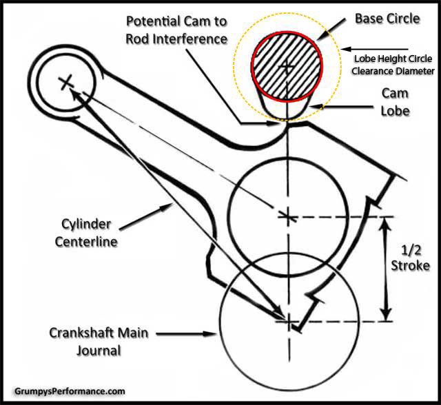
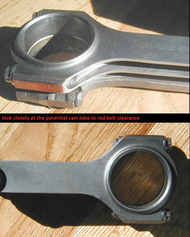
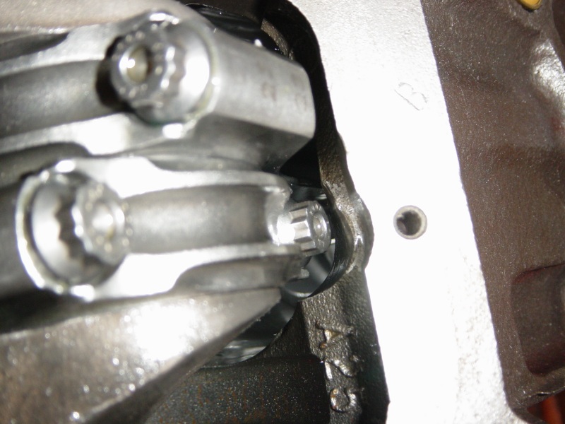
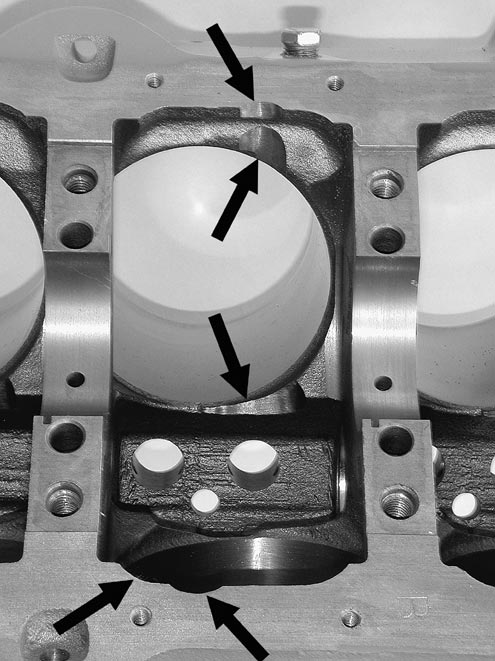
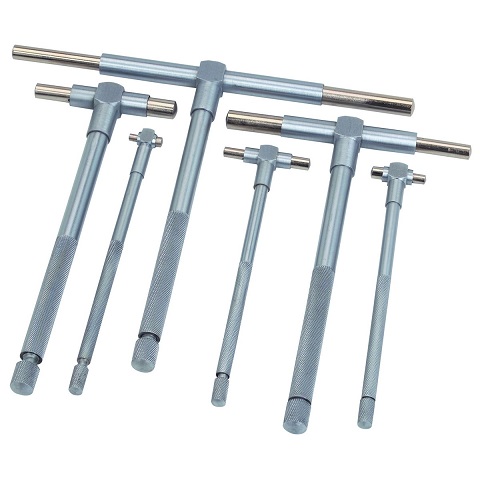
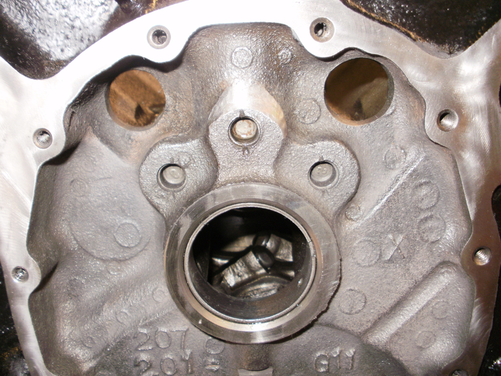
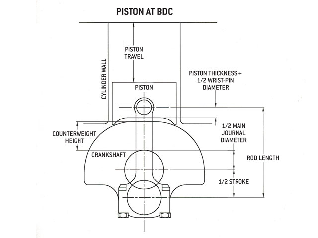
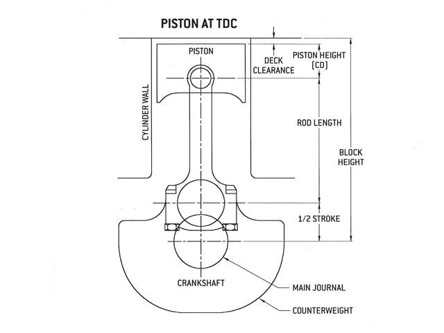
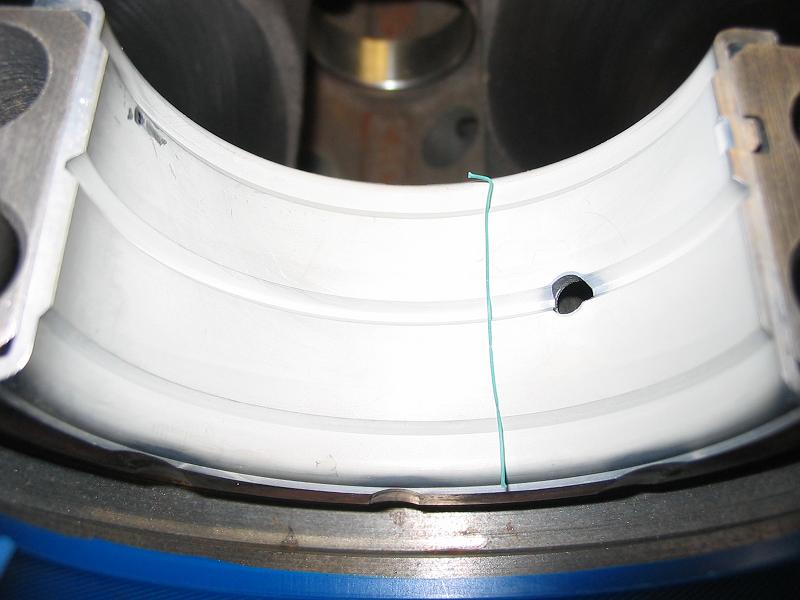
notice how the rod bolts come close to the cam bearings as the pistons reach top dead canter in the bores, this clearance must be individually checked and should be no less than about .060 (generally you cam use a LARGE plastic tie-wrap
https://www.amazon.com/BuyCableTies...D=41U9CtmwOuL&preST=_SY300_QL70_&dpSrc=detail
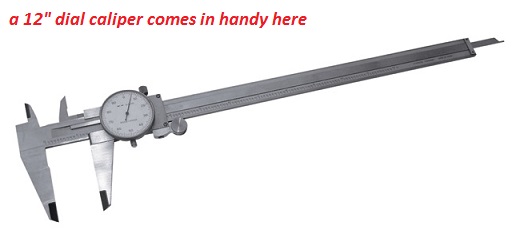
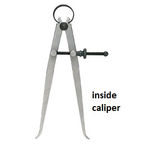
https://www.homedepot.com/p/General-Tools-12-in-Inside-Caliper-454-12/202545173?cm_mmc=Shopping|THD|G|0|G-Pro-PLA|&gclid=EAIaIQobChMI6J6Lq8Si2AIVlbrACh1ZWQfYEAQYAiABEgI5TfD_BwE&gclsrc=aw.ds&dclid=CLqo4rHEotgCFVLZwAod5HoAtg
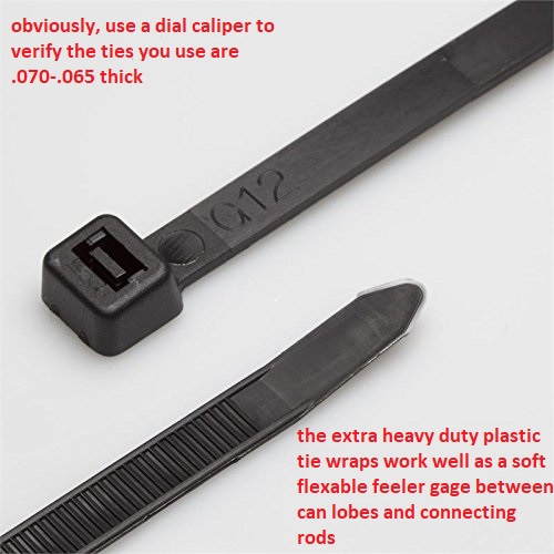
placed between the cam lobe and connecting rod bolts or connecting rod shoulder areas to check clearances as the soft tie-wrap will not damage the cam lobe while you verify clearances)you must install the timing set and index the cam correctly to get a valid clearance , as the cam lobes rotate and at some point they can be incorrectly indexed too hit the rods, while they would not if correctly timed.
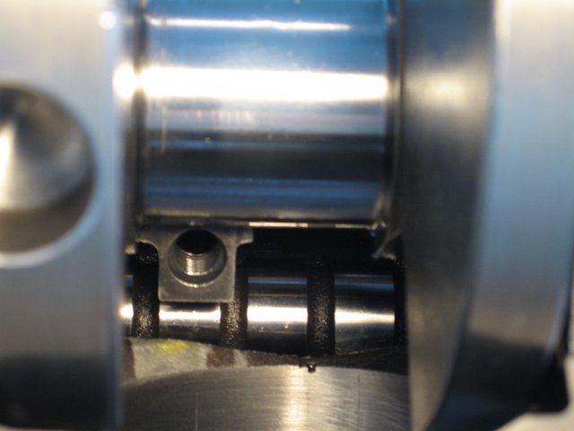
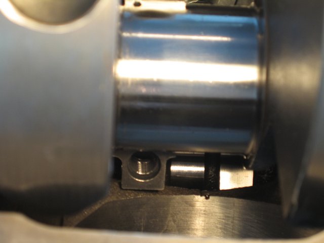
RODS WELL AWAY FROM CAM LOBES
RODS CLOSE TO CAM LOBES
WITH THE CORRECT SOFT WARE BOTH THE PISTON TO VALVE CLEARANCE AND CAM TO ROD CLEARANCE CAN BE CALCULATED
BUT ANY COMPETENT ENGINE BUILDER WILL PHYSICALLY VERIFY CLEARANCE
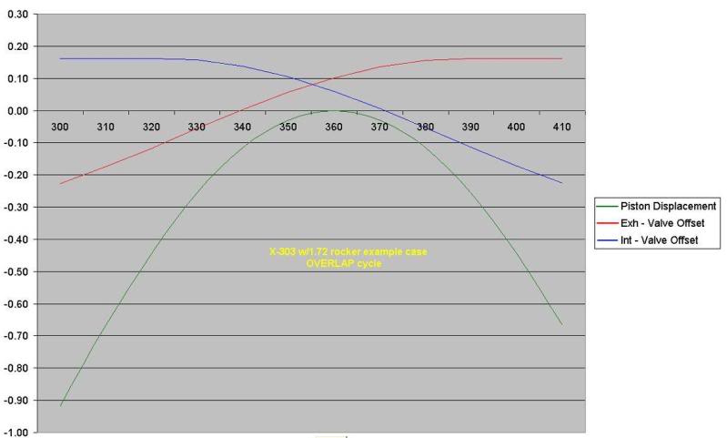
NEVER GUESS, DEAL IN PROVEN FACT!
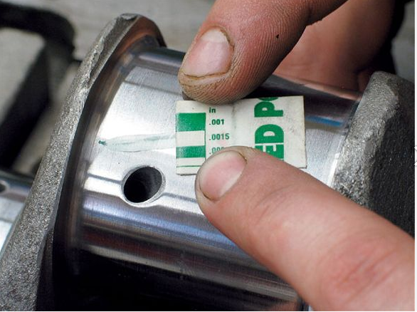
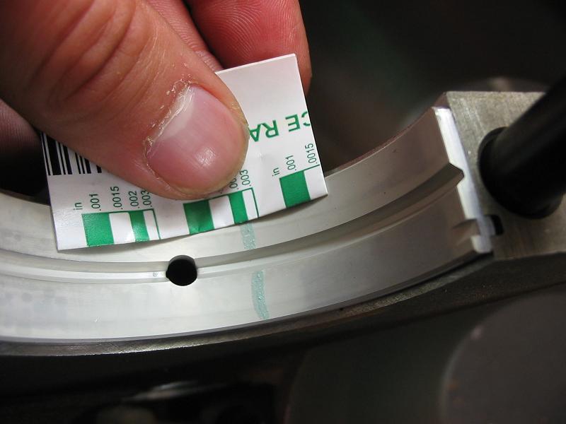
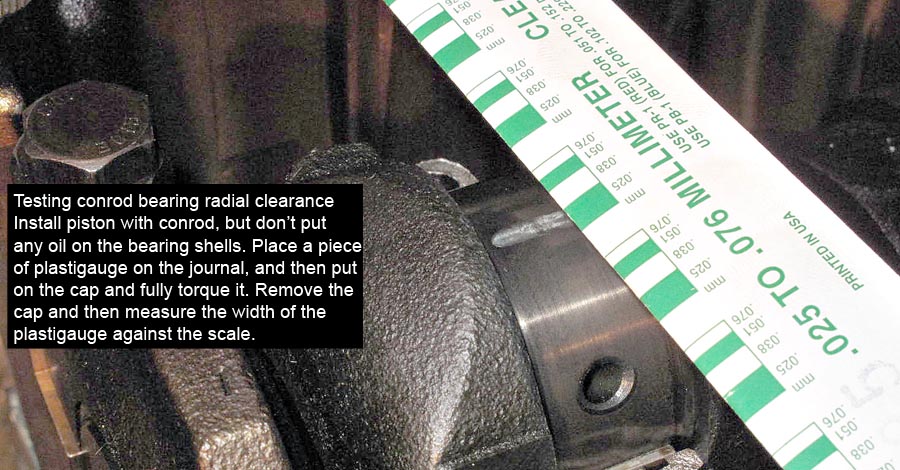
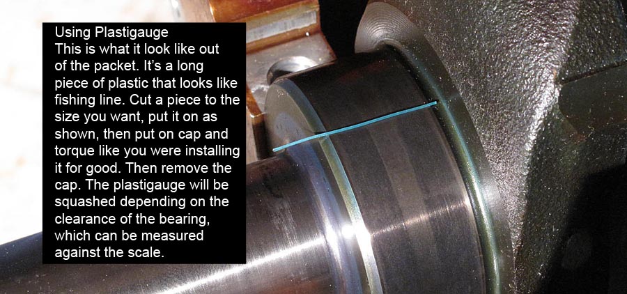
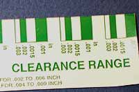
Id get out the plasti-gauge and check clearances, don,t guess , know exactly what your dealing with!
if the clearance falls in spec and the bearings look decent they can be re-used, but its foolish to do so if they look overly dirty, worn or don't have the correct clearances
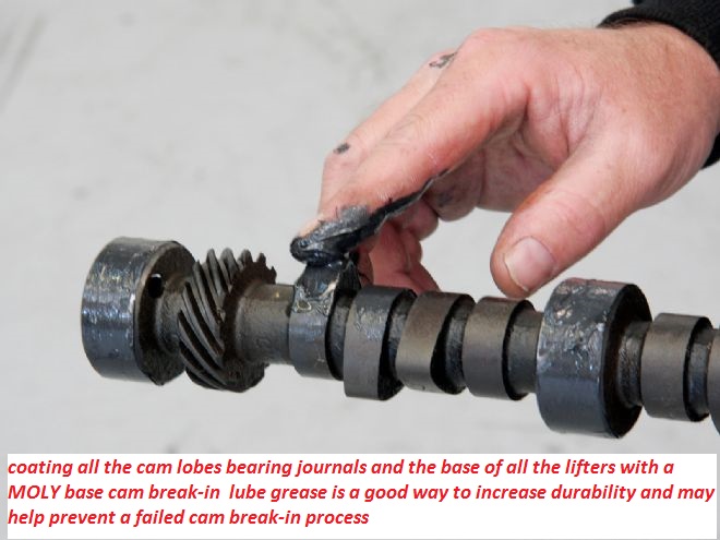
lots of moly assembly lube and spraying any potential moving contact surface with moly spray (like bearings ,lifters rockers) and liberal use of moly assembly lube during the break-in process helps reduce wear issues

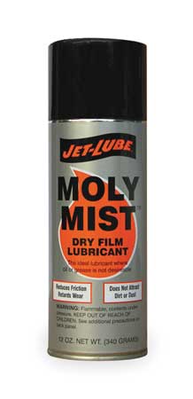
pre-spraying all bearing and valve train components with a moly based spray, helps embed micro moly lubricants in the metallic surface micro fissures , a good paste lube like cranes assembly lube over the spray surface helps insure a good lubricant surface coating, that is far stronger than just the ZINC and PHOSPHATES in oil
CAREFULLY.. reading links and SUB LINKS is almost mandatory on this web site!
if you want all available useful related info
http://garage.grumpysperformance.co...earances-and-journal-surface.9955/#post-38385
http://garage.grumpysperformance.com/index.php?threads/bearing-clearances.2726/#post-26440
http://garage.grumpysperformance.com/index.php?threads/can-you-reuse-bearings.5544/
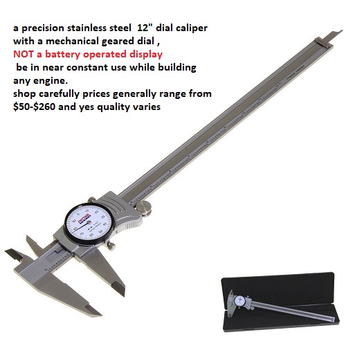
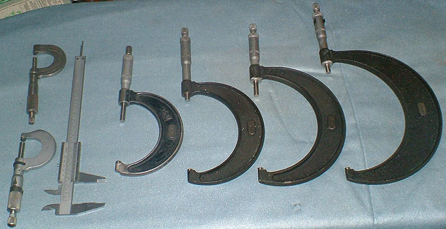
http://garage.grumpysperformance.com/index.php?threads/precision-measuring-tools.1390/#post-68194
http://garage.grumpysperformance.co...tion-of-crank-durring-short-blk-assembly.852/
http://garage.grumpysperformance.com/index.php?threads/assembly-lube-summary.6352/#post-68508
http://garage.grumpysperformance.co...ear-articles-you-need-to-read.282/#post-57371
related links with a great deal more info.
http://garage.grumpysperformance.co...g-and-installing-connecting-rods-pistons.247/
http://garage.grumpysperformance.com/index.php?threads/bearing-clearances.2726/#post-43385
http://garage.grumpysperformance.co...guess-on-clearances-and-journal-surface.9955/
http://garage.grumpysperformance.co...kshaft-and-connecting-rod-compatability.9320/
https://www.mahle-aftermarket.com/m...b-2-1114-engine-bearing-failures-brochure.pdf
https://www.enginebuildermag.com/2016/04/high-performance-engine-bearings/
https://www.substech.com/dokuwiki/d...liable_press_fit_of_high_performance_bearings
http://garage.grumpysperformance.co...d-rod-orientation-clearance-issues-etc.16027/
http://garage.grumpysperformance.com/index.php?threads/what-con-rods-would-you-buy.942/
http://garage.grumpysperformance.com/index.php?threads/rotating-assembly-bearings.9527/
http://garage.grumpysperformance.co...tion-of-crank-durring-short-blk-assembly.852/
the rods having two types of bearing tab locations is
not an issue if the connecting rod was properly resized,
and bearings match the intended application,
and rotating assembly components being used, clearances
http://garage.grumpysperformance.com/index.php?threads/virtual-dyno-software.2301/#post-53646
http://www.auto-ware.com/software/eap/eap.htm
rods designed like the 3 SERIES generally won,t work with stroker cranks while the 2 series usually will
the connecting rods you sellect make a huge differance in the rod to cam lobe clearance, even a small base cam won,t clear some designs, it should be obvious that the connecting rod with the thru bolt has a great deal less cam lobe clearance potentially than the cap screw design next to it., and the cap screw rod probably clears the blocks oil pan rail area easier also
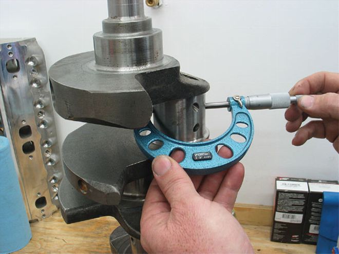
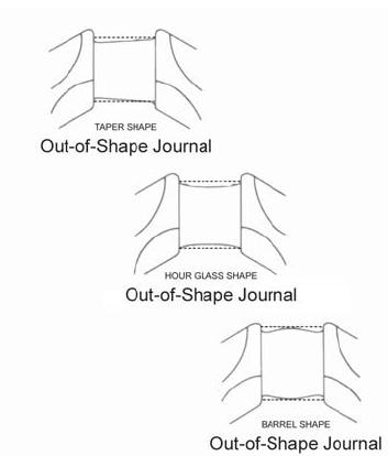
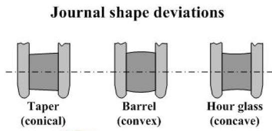
MEASURE CAREFULLY

viewtopic.php?f=44&t=10923
without pictures and measurements of that crank journal, that questions a bit like asking how pretty the next girl thru the door might be based on the color of her tooth brush at home!
reading a few links and sub links carefully could save you a lot of money and time
viewtopic.php?f=53&t=9214&p=33116&hilit=crank+journal#p33116
viewtopic.php?f=53&t=2726&p=7077&hilit=plastigauge#p7077
viewtopic.php?f=59&t=1390&p=3073&hilit=precision#p3073
viewtopic.php?f=53&t=5478&p=16429&hilit=plastigauge#p16429
Im rather confused, why not just have a local machine shop, inspect both cranks,and either cut and polish any worn crank journal on the best of the two,to a standard under size , and supply matching new bearings or buy a new crank, they just are not that hard to find at a decent price.
and while your at it why not have the local machine shop inspect your block, and it necessary bore and hone it if it checks out as rebuild-able?
not much point in building an engine without building it to function and last a long time, and you do that my making sure all the components fit and function as designed with the proper lubrication,oil flow,oil pressure, compression and clearances
New
Hi Grumpy,
I caught your article on Journal measurements and would really appreciate your perspective on the followng questions. (background blather appears below the questions)
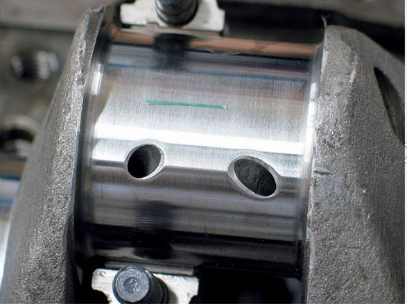
1) Shouldn't the journal in your article have looked shinier if it was a finish cut ? (see background below)
90% or more of the pictures were and are posted by other people on the internet , and merely used to illustrate, yes ideally a finish journal should be as close to mirror finished and glass smooth as you can get it, but level, from end to end except for the curved machined bevel,on each end ,its diameter concentric and even in its dimensions its intended and ideally standard size or standard under size, is critical
2) Is there a need to plasti-guage a daily driver crank (no racing) that's been resurfaced to a matching set of bearings ? I actually thought about plasti-gaging the journals rods from underneath (one location) but taking 6 measurements per makes removing the crank seem easier to do. I will definitely check for debris and burrs on future kits however.
its always a good idea to verify machine work, theres always some machine shops that either do low quality or shoddy work, and you can,t expect an engine to operate correctly if the clearances or consistency of the bearing and lubrication surfaces are not correctly set, you would not bet the first or last guy to be told a crank was cut to a size that was not the true size or sold the wrong bearings for an application, you should always verify machine work, with both a precision measuring tool and plasti-gauge
MEASURE CAREFULLY
http://garage.grumpysperformance.com/index.php?threads/can-i-get-it-polished.9214/
http://garage.grumpysperformance.co...guess-on-clearances-and-journal-surface.9955/
http://garage.grumpysperformance.com/index.php?threads/bearing-clearances.2726/
http://garage.grumpysperformance.co...tion-of-crank-durring-short-blk-assembly.852/
http://garage.grumpysperformance.com/index.php?threads/rotating-assembly-bearings.9527/
3) Do you have any experience doing the crank kit right in the Caprice (without removing engine)
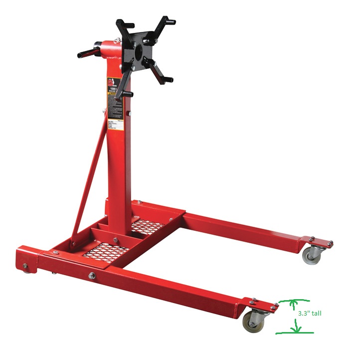
no I have always found it best too assemble an engine after placing it on a decent engine stand
if your going to assemble an engine you should buy or rent a decent engine stand, and a few basic tools
http://garage.grumpysperformance.co...g-with-a-local-machine-shop.14419/#post-74383
http://garage.grumpysperformance.co...haft-journal-surface-finnish.2728/#post-72043
http://garage.grumpysperformance.com/index.php?threads/precision-measuring-tools.1390/#post-68850
4) I didn't understand from the graphs posted. What is a 180 'bearing' whatever vs a 270 ? and which is best and why ?
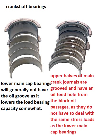
a 180 degree bearing has only the upper in the block grooved to improve oil flow,a 270 degree has the oil feed groove extend further 45 degrees on each lower bearing shell
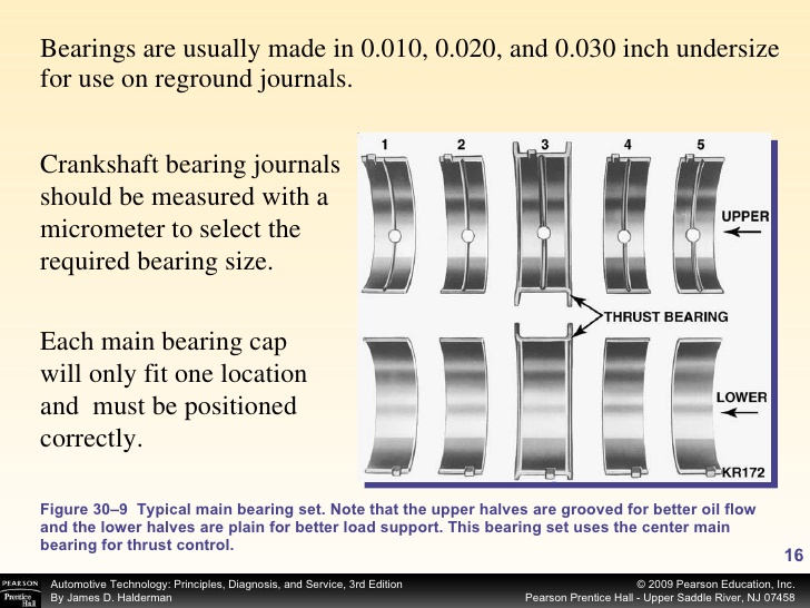
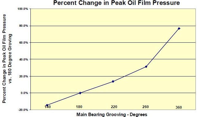
MAIN BEARINGS WITH 360 degree oil grooves
I've got my grandmothers 86 caprice that still looks really good and never fails to turn heads. Bone stock, but most of the cars been painted over 23 years I've owned it by a company that guarantees paint for life. More importantly this car has been just amazingly reliable over the years. Now that my son is ready to drive it (17) I'm noticing the engine shudders as second winds out so the bottoms loose with mileage just under 199K. I'm far from expert so did some googling and found your journal article.
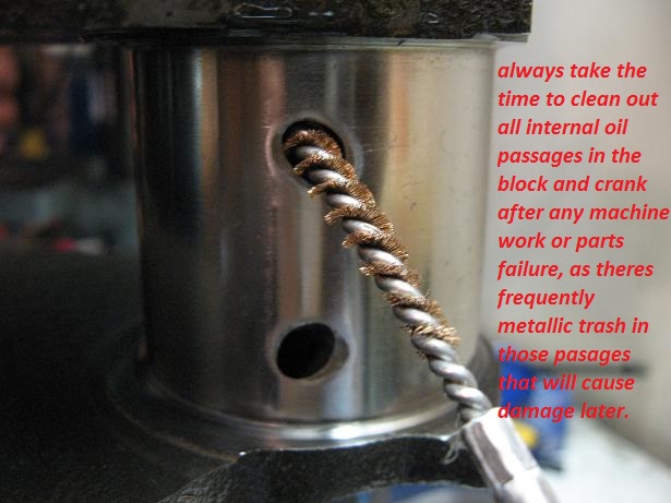
I have done two crank shaft kits over the years - while the engines remained in the vehicles. 1975 and 1979 350 Chevy pickups. After reading the article I"ll have to say I don't recall checking nor deburing the oil passages - which would have been colossally easy to do. Will do so going forward. In both instances I pulled the crank had them resurfaced then bought bearings of matching thickness. The shop I turned the crank in 1990 has since closed so I'm checking out machine shops.
Note: The journal image in the article didn't look very shiny. Back during my 1990 crank kit install, I had the good fortune of comparing the journals of a crank that had been rough cut (per a racing engine builder) with my crank done by a shop owned by guys that raced engines. The difference was remarkable. I could easily see my pores, individual pores etc.. in the journals. They were mirrors. I installed it and drove my pickup daily to work 15 more years until gas hit $4/gallon then switched to the subject Caprice. Now my
viewtopic.php?f=51&t=125
http://garage.grumpysperformance.co...uring-crank-bearing-journals.5478/#post-16429
viewtopic.php?f=54&t=1479
viewtopic.php?f=51&t=976
viewtopic.php?f=51&t=7697
viewtopic.php?f=53&t=852
viewtopic.php?f=53&t=247
Last edited by a moderator: