Dynamic And Static Compression Help

Jorandom

Member
Hello everyone. I have something i am needing help with. And i would be ever so grateful for any advice.

I have a 1994 chevy 3/4 ton 4x4. Extended cab it has 3.73 gears and a built 4l60E trans. 1800 stall. The engine in it now is getting pretty tired and i am fixing to start putting together a 383 for it. I have the block, crank and rods for it but i am trying to figure out what pistons to get.

The heads i have are https://www.summitracing.com/parts/sum-152123

I will set the quench around .040. I am going to be doing some lite to moderate towing. Sometimes and i want to run 87 octane. Without having to retard the timing.

The cam i am going to run is a http://www.competitionproducts.com/...14_214-050-443_443-112-LC/productinfo/E1029M/

Any help would be greatly appreciated. Thank you.

index.php


index.php
 

Attachments

  • 54F4FFA9-1A07-4F9B-A35F-D3134E9C244A.jpeg
    54F4FFA9-1A07-4F9B-A35F-D3134E9C244A.jpeg
    127.9 KB · Views: 97
  • 634C7098-CFE7-489D-8FA3-1BF006B98C5F.jpeg
    634C7098-CFE7-489D-8FA3-1BF006B98C5F.jpeg
    111.8 KB · Views: 96
Last edited by a moderator:
assuming you want to run cheap crap gas occasionally ,
I would limit compression to about 9.4:1 -9.6:1 static and
strive too get about 7.8-to-8:1 dynamic compression :D

with a 72 cc combustion chamber on a 383 with a .040 quench and a 17.8cc dish piston,
and the chart you posted show your potentially going to be hurting your engines potential with a bit too low of a dynamic compression, if you select a deep dish piston design
that 17.8cc dish with a 72cc combustion chamber might lower the compression a bit more than ideal.
Id be looking for about a 13cc-15cc cc dish piston if its my engine build
ideally youll select a piston that provides you with the required static compression.
it may help if you know the intake valve seat timing as some calculators will require that info
now certainly take the effort to do the required calculations for yourself,
but try to get the dynamic compression up near 7.8:1-8.0:1
keep in mind you can leave the cam at 4 degrees advanced,
or retard the cam to the strait up or split duration index ,
on its install to play with the results,
you also have the option of swapping cams
if you use that 17.8cc dish it will work just fine,
but you'll be down on the torque a bit,
from where the engine could potentially be,
with that extra bit of compression

keep in mind DYNAMIC compression is the ONLY thing you need be concerned with,
static compression is simply a point in calculations,
as the engine never sees static compression


http://garage.grumpysperformance.co...hanics-of-adv-ret-a-camshaft.4532/#post-12045


http://garage.grumpysperformance.co...ng-cam-and-shifting-the-lca.10553/#post-44949

http://garage.grumpysperformance.co...temps-detonation-resistance.12842/#post-66481

http://garage.grumpysperformance.co...ng-combustion-chambers.2630/page-2#post-54342

index.php

Octane_Requirements.gif

vechart.gif

Stoich.gif


Detailed Description you listed for your cam
clear.gif


Part Type: Camshaft & Lifter Set
Application: Chevrolet Small Block 262-400 1955-2002Ignition Firing Order: OE (1-8-4-3-6-5-7-2)
Cam Style: Hydraulic Flat Tappet
Basic RPM Range: 2000-4800

Manufacturers Description: Mild idle, improved power and torque. Works with stock converter.
Intake Duration @ .050": 214
Exhaust Duration @ .050": 214
Advertised Intake Duration (@ .006"): 280
Advertised Exhaust Duration (@ .006"): 280
Intake Valve Lift with OE Rocker Ratio (1.50): .443"
Exhaust Valve Lift OE Rocker Ratio (1.50): .443"
Intake Lobe Lift: .295"
Exhaust Lobe Lift: .295"
Intake Valve Lift with 1.55 Rocker Ratio: .458"
Intake Valve Lift with 1.60 Rocker Ratio: .472"
Intake Valve Lift with 1.65 Rocker Ratio: .487"
Exhaust Valve Lift with 1.55 Rocker Ratio: .458"
Exhaust Valve Lift with 1.60 Rocker Ratio: .472”

Exhaust Valve Lift with 1.65 Rocker Ratio: .487”

Lobe Separation Angle: 112 Degrees
Intake Centerline: 107 Degrees
Lifters Included: Yes, PVT652394, Hydraulic Flat Tappet

Small Base Circle: NoCam Gear Attachment: Single-Bolt
Valve Adjustment: Zero Lash Plus ½ Turn
Manufacturer: Elgin Industries
Manufacturer's Part Number: E1029M
Weight: 10.0 lbs.


CrowerCamTimingChart_112-114.jpg


http://victorylibrary.com/mopar/cam-tech-c.htm

http://members.uia.net/pkelley2/DynamicCR.html

http://www.wallaceracing.com/dynamic-cr.php

http://www.pcengines.com.au/calculators/Calculate dynamic Comp Ratio.htm

http://garage.grumpysperformance.co...-calculators-and-basic-math.10705/#post-72061

http://garage.grumpysperformance.com/index.php?threads/dynamic-vs-static-compression.727/

http://www.wallaceracing.com/cam-deg-calc.php

http://garage.grumpysperformance.com/index.php?threads/checking-piston-to-valve-clearances.399/

http://garage.grumpysperformance.co...octane-for-compression-ratio.2718/#post-86754

http://garage.grumpysperformance.co...e-springs-and-setting-up-the-valve-train.181/

http://garage.grumpysperformance.com/index.php?threads/crowers-valve-timing-charts.4299/
 
Last edited:
Thank you very much Mr GrumpyVette. I am going to read all this carefully and dig a little deeper into this information. And calculations. I appreciate the help!
 
index.php


yes that combo is going to be much closer to ideal,
you have found a combo like that too be almost exactly what your looking to build!
 
The thing that confuses me is the lobe intensity between the cam manufacturers Seat dur. And dur. At .050. I have heard that you dont want a intensity no lower than like 48 if i am remembering right. Kinda like the 2 cams i posted. The first one would appear a little lazy to me. But... that makes me think that is why you use the intake valve closing angle. Whould the lazier cam/less intensity bleed off more cylinder pressure?
 

Attachments

  • 5C62FF17-2358-4C2A-A8F5-7D06C7ABC43B.png
    5C62FF17-2358-4C2A-A8F5-7D06C7ABC43B.png
    179 KB · Views: 6
  • 25EDADF9-FDFC-44C1-943D-C5A1E342AA91.png
    25EDADF9-FDFC-44C1-943D-C5A1E342AA91.png
    151.3 KB · Views: 6
  • 6A597756-FD9F-437C-8F36-3089EC49929E.png
    6A597756-FD9F-437C-8F36-3089EC49929E.png
    267.8 KB · Views: 6
  • 843F501F-1B98-4D9C-A103-49AD4B85D4F5.png
    843F501F-1B98-4D9C-A103-49AD4B85D4F5.png
    177.6 KB · Views: 6
  • 4C451558-9DD3-4645-968D-D1D0696FBAFA.jpeg
    4C451558-9DD3-4645-968D-D1D0696FBAFA.jpeg
    81.3 KB · Views: 6
  • A06655C5-9EE3-4C41-960A-82D4CD48615F.jpeg
    A06655C5-9EE3-4C41-960A-82D4CD48615F.jpeg
    71.6 KB · Views: 7
keep in mind a" LAZY " cam, might be far better for low wear and increased durability,
engineers that design a cam and valve train, need to know whats expected,
any cam may be significantly easier on the valve train and increased durability may be greatly enhanced or extended OR peak power might be the goal,
minor changes can have very significant effects on durability without changing power very much,
both CRANE AND CROWER are rather well known of tending too design cams that might sacrifice a couple peak horsepower,
if it required to significantly boost long term durability and reduce the chances of valve train stress levels,causing problems.
some other company's have a few cam lobe designs that are right at or even at times in some rpm ranges a bit past the limits,
of what most builders might see as reasonable for longer term durability,
they seem more concerned with being able to produce the best possible peak power,
even if doing so might reduce the engines longer term life expectancy.
a cam designed for drag racing that might be expected to make peak power for less than 15 seconds at a time will be a great deal different,
than one in an engine designed to run the 24 hour race at le-mans,
even if both cars ran in a car with a similar engine family,
and certainly both would be designed far differently than a cam designed,
to run issue free for 100K miles
a difference in philosophy ,
one group thinks you have to finish the race to win,
most guys don,t have unlimited cash so lets design something that will last a long time without issues!

the other group thinks, youll never win unless your making the most power available,
and race engines get torn down , inspected and re-built regularly so push the limits


Isky claims that the Comp XE cams violate the 47.5% rule. The 47.5% rule applies to flat tappet cams for SBCs with 1.5 rockers but the concept is still the same for other configurations where the designs are "on the edge" or "over the edge" for lobe intensity. For 1.5 ratio SBCs, the duration at .050 must exceed 47.5% of the total valve lift or your asking valve train problems. For example, take a Comp Cams Magnum 280H, with 230 duration and, 480 lift...230/.480 = 47.9% which exceeds 47.5% therefore would not pose a threat to components. We do not regularly hear about the older, safer HE and Magnum designs rounding off lobes anywhere near as often as the XE cam designs. Unfortunately, some of the Comp Cams XE dual pattern lobes break this 47.5% rule on the intake side so they are likely to be problematic. The design has "steeper" ramps that are too quick for durability and reliability according to other cam manufacturers. They will wipe lobes in a heart beat especially if you have not followed the proper break-in procedure. Other designs are more forgiving during break-in and less likely to fail.
 
Last edited:
Would you happen to know where i can find any information on isky cams? Specifically the 262 supercam and 264 Megacam ivo,((ivc)),evo,evc. (For calculating DCR and ICL) basically cam cards :). And another question is where do they measure their adv duration. Can you reference them with other cam manufacturers @.50 dur. ? Their advertised RPM Range is also throwing me for a loop. Is it accurate? Any help would be greatly appreciated.
 
heres some related info you'll want, if you can,t do it else ware,
you can take the .050 duration on almost any cam,
use the info and lsa on the crower valve timing chart and add 15 degrees to both timing figures
and youll be close to the seat timing on most cams to use the results for calculating compression.

http://www.iskycams.com/shop/

http://www.iskycams.com/userfiles/files/ISKY-Master Lobe List.pdf

http://garage.grumpysperformance.com/index.php?threads/how-to-read-a-cam-spec-card.1477/

http://garage.grumpysperformance.com/index.php?threads/crowers-valve-timing-charts.4299/

http://garage.grumpysperformance.com/index.php?threads/dynamic-vs-static-compression.727/


http://garage.grumpysperformance.co...e-required-octane-for-compression-ratio.2718/
heatvscpr.jpg

postiongraph.jpg


0607phr_11_z+camshaft_basics+lobe_centerline_angle_determination_chart.jpg
 
Last edited:
Would you happen to know where i can find any information on isky cams? Specifically the 262 supercam and 264 Megacam ivo,((ivc)),evo,evc. (For calculating DCR and ICL) basically cam cards :). And another question is where do they measure their adv duration. Can you reference them with other cam manufacturers @.50 dur. ? Their advertised RPM Range is also throwing me for a loop. Is it accurate? Any help would be greatly appreciated.

I use the ISKY 264 Mega in my 334 SBC. Here are the notes from my build:

Camshaft new ISKY
Grind No./Type: 264-MEGA HYDRAULIC FT**
Application: Tremendous torque & good mid-range power.
9-10.5:1 compr., good idle, stock converter.
3.23-3.70 axle ratio. Up to 625 CFM Carb.
RPM-Range: 2000-5800
Valve Lift Int/Ext: .450/.450 (1.5), .480/.480 (1.6)
Valve Lash Hot Int/Ext: .000/.000
ADV Duration Int/Ext: 264/264
.050 Duration Int/Ext: 214/214
Lobe Center: 108 108° LSA /108° ICL = straight up

There is also another cam that's tried and true and that's the 213/219 .493/.502 HR112 74216.
The 219/219 .560/.560 HR112 74219 is not bad either.
215/218 dur, .490/.490 lift, 112 LSA full roller cam.

Seat-to-seat timing (Wallace) (IN .007", EX .010") ISKY

IVO is 24.0 ° BTDC (- indicates ATDC)
IVC is 60.0 ° ABDC
EVO is 60.0 ° BBDC
EVC is 24.0 ° ATDC (- indicates BTDC)
Overlap is 48 °

.050" Valve Events – IN Opens 1 ATDC IN Closes 35 ABDC
EX Opens 35 BBDC EX Closes 1 BTDC

P-V clearances happen at TDC - .228" for the Exhaust and .192" for the Intake.

Dynamic Compression Ratio Calculator
(Use seat to seat specs for Intake spec for best results)
Number of Cylinders : 8
Bore in Inches : 3.766
Stroke in Inches : 3.75
Rod Length in Inches : 5.7
Static Compression Ratio : 9.87:1
Inlet Valve Closes ABDC : 60 º (.007")
Boost Pressure in PSI : 0
Target Altitude : 177 (Feet)

Static compression ratio of 9.87:1.
Effective stroke is 3.05 inches.
Your dynamic compression ratio is 8.18:1.
Your dynamic cranking pressure is 163.62 PSI.
V/P (Volume to Pressure Index) is 133


RICK'S Calculator says: SCR = 9.87, DCR = 8.21, Cranking Pressure 169.26#

From Brian's chart, I can get by with 91 octane (175-185 psi)

Less than 8:1 DCR is sluggish response and/or leaving performance and economy on the floor.
8-8.5:1 is the sweet spot.
Above 8.5 DCR requires race gas to prevent detonation.
These are general guidelines that depend on the rest of the package (cam lift, head flow, operating temp, etc).

Lifters new ISKY Quiet Power 202HYAnti-Pump-Up
Hydraulic flat tappet Superlifters (2 oil holes)
Manufactured by Johnson/HyLift/Topline

Springs ISKY 235D
Type/MatL: OUTER W/DAMPER (CHROME SILICON)
Color Code: BLUE
Individual Spring Part Numbers IN/O: N/A
O.D.: 1.260
I.D.: .886
Seat Pressure: 130 lbs @1.750
Open Pressure: 320 lbs @1.200
Rate Per Inch: 350 (I calc 345.45#)
Coil Bind: 1.150
Max Net Lift: .550

tip conditioning on both ends, including dampers, by me

Heated ISKY valve springs in oven to 220°F and soaked them in the drained
and strained break-in oil before dumping it back into the engine.

Using Alex's (extra clearance – retainer to seal) 99100-1 retainers (16 gm) and
Crane Machined STD locks for an installed height of 1.800" (calc 112.5# seat, 278# open),
measured with my spring tester – 124# seat, 304# .480" lift

.900" – bottom of retainer to top of valve guide
.750" – retainer to valve seal (Alex fixed-body .558")
.270" clearance retainer-to-seal (.750 - .480 v.l.) (.090" min preferred, .060" min)
.170" clearance before coil bind (1.150") (.060" min preferred)

**With this camshaft, ISKY recommends: (1.700")
ISKY - VALVE SPRINGS 205D Type/MatL: DUAL W/DAMPER (CHROME SILICON)
Color Code: YELLOW
Individual Spring Part Numbers IN/O: N/A
O.D.: 1.260
I.D.: .886
Seat Pressure: 115 lbs @1.700
Open Pressure: 268 lbs @1.210
Rate Per Inch: 310
Coil Bind: 1.160
Max Net Lift: .490
 
Last edited:
Thank you guys soo much. I greatly appreciate it. So much experience and knowledge and yall are willing to help. Im Truly grateful. Im gonna do some more studying and figuring. :)

How do you like that cam? (264mega) how does it drive? Is it best to install it straight up or on a 104 icl? According to Joe Sherman that he and some others like to use them in 383’s sometimes says they are really good in the 2500-3500 rpm range.

This truck will be carbed and no catalytic convertor. Free flowing new exhaust.
 
The engine is still on the test stand. :( So I don't know how it drives - yet. But from the way it runs on the stand, I LIKE IT.
But look at all the numbers I posted. I wanted it to run on pump gas (93 octane if necessary) without pinging or detonation.
That's why I went for a DCR of about 8.1 to 1. The ISKY 264 Megacam gives me that with it's 60 degree IVC closing point.
Split duration camshafts that favor the exhaust side are an attempt to compensate for a poor exhaust port and/or restrictive exhaust systems.
If you find the text where ISKY explains their thoughts about cams, ..... I'll find it for you - I don't want to get it wrong.
You need to think about your entire combo, not just combining individual parts and hoping that they will play nice with each other.
 
http://www.iskycams.com/advanced-design.html
http://www.iskycams.com/tech-tips-2000.html READ THESE, esp. Tech Tip - 2003
Longer Exhaust Duration: Is this really necessary?
https://www.scribd.com/doc/244195852/Valve-Timing-for-Max-Output

If you'll recall in last months tech tip: "Longer Exhaust Duration: Is This Really Necessary?" I discussed how, through habit, many racers and cam grinders alike are predisposed to running camshafts with longer exhaust durations, whether they need to or not! Well, in the case of restricted intake applications, if there was ever a situation in which you'd want to avoid the longer exhaust "trap" it's here! Especially the 8, 10, 12 or even longer degree spreads, I often discover people employing.

Use such a cam at you own risk - and don't be surprised to find that your exhaust temperatures are unusually high. Your headers in fact may even glow cherry red. There is a very good reason for this. Raw (unburned) fuel is burning "late" or in the pipe (header/manifold). You may have a good equilibrium of flow going here but there is just one problem. Much of what should be inducted into the cylinder is being scavenged out the exhaust!

EXFLOWZ5.jpg
 
Last edited:
043EAE6D-4955-4D08-8A93-B8D94D72A8BF.png 3BD32E76-70C9-419A-B959-C65286D9777B.png E22EE218-AE0D-436C-B267-0CC0F94D90BB.png 32DD880B-6ABF-47B9-AF95-FBE96E693D24.jpeg 93504ACE-2035-46E0-BB9A-CA6AC00C5532.jpeg I will tell you my thinking on this combination. Or what i have calculated.

The heads are SUM-152123 and from my understanding they are supplied by dart to summit. 1.75 csa

4.030 bore/3.750 stroke divided by 8=47.83 ci per cylinder.

Torque peak Rpm 1.75 CSA x 88,200 Divided by 47.83= 3227 RPM
————————————————————
Edelbrock eps says tit is tuned to 3500 rpm torque with a 350. I subtract 300 rpm and that comes out to 3300RPM
————————————————————
Header cross section for 18 ga 1.5” header is csa 1.552.

Csa=peak torque Rpm (2863 Rpm)X 47.83 divided by 88,200.
————————————————————
(The 1 5/8 headers torque peak is around 3400 RPM.). The reason i am leaning towards the 1.5” headers is velocity And a dyno test (also hence the 165cc runner heads). This is a budget build and i will be running 87 octane 100% of the time. The exhaust is gonna be 1.5” mid-length headers with 2.5” collectors. 2.5” pipe off the headers to a Y pipe. After the Y pipe is gonna be a 3” pipe to a 3” in/ 2 .25 dual out muffler. 2.25 duals out to the bumber. (Exiting on the sides of the hitch)


Does this seem logical? What do you think on this? This is according to these books.
 
Thats exactly what led me to want a single pattern cam. And i have been thinking. David vizard emphasizes on a narrow lsa. Being on a lower duration. Maybe have more torque around 3000 rpm ( where most of the other parts are tuned to). But i have others talking about needing it to be on a 112 LSA and vizard says its a crutch for too much duration. If i understood correctly.
 
Tech Tip - 2001
postiongraph.jpg


Compression Rules: "The Joker in the Deck"

In order to hold costs down in oval track racing today we have numerous "RULE" classes. Cam "Lift" rules, engine "Vacuum" rules, "Carburation" rules and of course "Compression" rules. I for one, certainly have no quarrel with compression Ratio rules, because if you are talking true compression ratio, and it's properly measured and enforced, it is absolute. On the other hand, if it's a "compression effect" rule or the measurement of cranking compression in the cylinder as read on a compression gauge, then you have just pushed one of my buttons! However, before I begin my tirade, let us review why we have such rules as these in the first place. Do they exist so that we can go faster or slower; to make racing more or less competitive? And, are those who break such rules punished or rewarded? Well you say, the obvious answers to these questions are "slower", "more competitive" & "punished". Wrong! Not when it comes to compression "effect" rules!

Very simply, with a carburetor rule, he who installs a "bigger" one usually goes faster, can be detected and penalized. Likewise with a "cam lift" or "engine" vacuum rule. You cheat by installing a bigger cam and although you go faster, we can catch you and "you're outta there". Even with a compression ratio rule, you can have your "15 minutes of fame" if you like, but eventually you're going down because we can detect your indiscretion.

However, guess what happens to those who comply with a "compression effect" rule? Why, they are virtually always running a larger camshaft, go faster and of course can never be punished because they are within the rules!

Impossible you say? Quite possible I contend and in fact this is actually what happens virtually 100% of the time! I know, I'm in the camshaft business! Simply put, I believe compression effect rules are the single most ridiculous rules in existence. Rules that guarantee to keep speeds up, not down and actually penalize those with weaker engines and fewer resources. How can that be? Please read on...

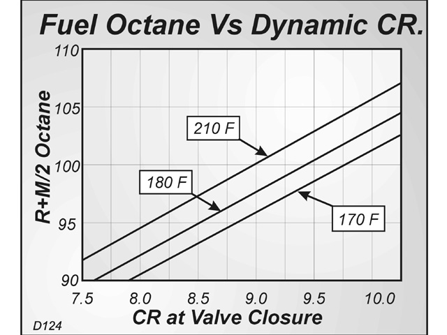
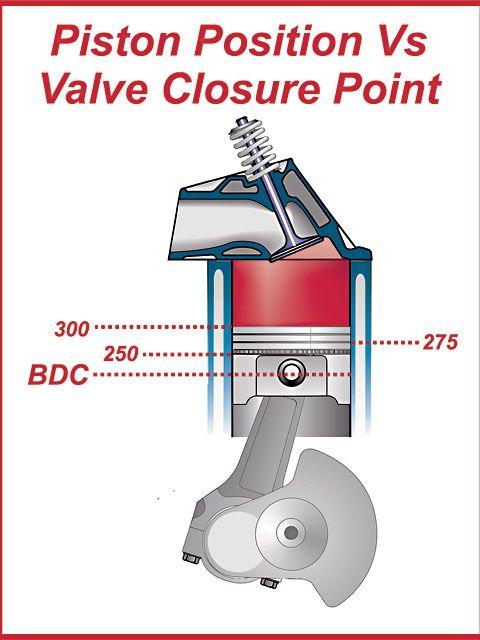
With a given static compression ratio, you will always have a higher reading on your compression tester gauge with a stock or low duration cam, because you will be closing the intake valve earlier on the compression stroke. The resultant longer effective compression stroke always delivers a higher gauge reading. Now switch to a longer duration cam. Your intake valve will close later, lowering your gauge reading because of the shorter effective compression stroke. Some people feel this is impossible, insisting that if it were true, why will you go faster with the bigger cam? The answer is, the bigger cam will have higher compression effect in the cylinder at higher engine speeds (where all that extra valve timing can do you some good), however at lower speeds and especially at starter-cranking speeds, the effect will be lower.

If you wish to prove this to yourself, simply recall how in the past you may have noticed losing bottom end torque when installing a longer duration cam. Do you think you lost that torque because of higher cylinder pressure? Of course not, but that is only the logic of deductive reasoning. Lord only knows what the "compression effect" rules people were thinking of when they came up with this stuff. It doesn't make sense and just about any cam grinder I know of, could have told them as much. On the other hand, there are some cam grinders who are confused about "compression effect" and cylinder flow dynamics. (Perhaps they consulted one of them.)

Tech Tip - 2003
Longer Exhaust Duration: Is this really necessary?

Most stock camshafts from American production V8, V6 and 4 cylinder engines manufactured today are ground with the longer exhaust lobe duration. Or, another way of looking at this is that they are ground with shorter intake durations! The former embraces the viewpoint that either the Exhaust Ports or Exhaust Pipe system is somewhat restrictive, and is in need of an assist. The latter suggests that the intake system is rather efficient and cam timing can be trimmed back a bit with out much sacrifice in power, in order to maximize throttle response and cruising efficiency.

Take your pick here. There is no absolutely correct viewpoint - because both are probably true! In a stock engine running at conservative RPM levels, for the sake of overall efficiency, fuel economy and a quiet smooth running engine, this staggering of intake and exhaust duration is quite common and appropriate.

However, High Performance is another thing entirely. Change one factor, let's say in this case, the exhaust system (installing headers and larger pipes) and you have just negated in most cases, the need for that longer exhaust lobe. Now couple this change with a different intake system and camshaft and you have really scrambled the equation. But, wait just a moment. Why is it that so many people (racers & cam grinders alike) insist on running a cam with longer exhaust duration regardless of what equipment is employed? The answer is "habit". Most of them have been somewhat successful in doing it their way and will probably never change unless virtually forced by circumstances to do so.

Before we go any further however let's review what it actually is we are trying to do with an engine when we attempt to make more power. Our best result comes when we are cognizant of the fact that an engine is basically an air pump. We pump it in and out (although in a different form) and we have problems when one side or the other is restricted. Balance or the equilibrium or flow should be our objective, unless of course we are not trying to make more horsepower!

Example #1 (Oval track racing) Here, I have often observed that the most experienced drivers are those who are most likely to run a single pattern (equal on intake and exhaust duration) cam. Why? Because such cams always, I repeat always make more torque! These veterans have a more educated foot and greater experience in feathering the throttle in the corners. They can therefore, utilize the benefit of added torque, in the lower to mid RPM range, to their advantage.

Their counterparts, the younger drivers on the circuit, generally are not as experienced and may at times actually get "crossed up" in the corners especially with a lighter car or when they are learning the ropes. In their case, a longer exhaust duration is often the more appropriate choice. It will often help them to drive better, more "flat footed" if you will, without consequence. But please for the sake of accuracy, let us be truthful. The benefit comes from an actual bleeding off of low to mid range torque, which is always what happens when Exh. Duration is lengthened, not from any improvement. The improvement, (if any) would come because of an improvement in scavenging at the extreme upper end of the power curve and would usually be marginal at best. Yet the so-called "extra power" potential of a longer Exh. Duration cam is most often why they are touted - power most people are backing away from at the end of the strait away!

Example #2 (Drag Racing) At the drag strip it's a little different and I feel more honest. Here, racers have long enjoyed longer exhaust and longer durations across the board (If I may add specifically for the purpose of "killing" low-end torque) to keep the tires from too easily breaking lose. This has been successful and sometimes actually results in a slight increase in top end power - something you can actually use in drag racing since it is a full throttle endeavor through the lights. Keep in mind here though, it's quite possible that a longer duration cam overall would have done just as well or better. In other words if you needed that longer exhaust for top end, perhaps the intake could have benefited from such a lengthening as well.

One of my favorite expressions is how "The Drag Racing mentality has infiltrated the ranks of Oval Track". Many have crossed over and made the switch in the past 10-15 years and some have brought their preconceived notions about how to cam an engine with them. A few may actually read these concepts and if they do so will at least come away with a better understanding of what they are doing. On the other hand they also could find that this information might actually help their cars to run just a bit faster!

Note: Readers may find Camfather Ed Iskenderian's Top Tuners Tip #33 "Can an Exhaust System Over-Scavenge the Combustion Chambers" to be a relevant precursor.


Last edited:
Cam shafts are so TECHNICAL now a days and each competitor may have their own grind specific for their purpose and not be on the open market for sale to all. One of the most easiest ways of cheating in any Motor Sport in my opinion with the exception of the carb which can have a myriad of internal and external changes to make the work more proficient.
 
Back
Top