ECU functionality

bytor

Well-Known Member
Since I have had my ‘new to me’ 1987 corvette for almost a year now and being the nerd that I am I wanted to know what made the 1227165 ECU tick. I thought I would start a post to generate some discussion. Obviously the 80’s ODB1 ECU’s are rather antiquated compared to today technology but it’s interesting to see how these things work. It’s helped me gain a deeper understanding of the TPI engine control rather than looking at the ECU as a black box. I have researched both the ECU hardware and software. Below is a summary of the ECU hardware and plan to follow up later with a software discussion. Disclaimer – I am in no way an expert involving this following info. It’s based on my research and I have made some assumptions and educated guesses. Feedback and additional insight welcome….

Starting off with the hardware, I put together a functionality block diagram below depicting the chips and their functionality inside the ECU providing a little more insight into what the inputs and outputs actually connect to inside the ECU. Also below is a description of the chips and generally what their functionality is I think. There is very little info out there on most of these chips.

ECU_block1.jpg


Description of the Chips:
16034988 (U8) - ECU main central 8 bit processor chip (CPU). The processor runs at a modest 2Mhz with 512K of SRAM on the chip. The upper 256K is retained by the car battery. This is where the ‘learned’ variables are stored (BLM) and what’s reset when the battery is disconnected. The architecture of this processor chip is almost the exact same as a Motorola 68HC11 with some minor differences. Motorola produced this custom chip for GM based on GM specifications. The programing instruction set is also the same as the 68HC11 and assembly language is used to write the code. This processor was used in most all of the GM P4 ECU’s thought the 80’s.
http://en.wikipedia.org/wiki/Freescale_68HC11
http://www.retro.co.za/rsre/efi/DIY_EFI/1999/efi4-117.txt
http://www.freescale.com/files/microcontrollers/doc/ref_manual/M68HC11ERG.pdf
https://www.clear.rice.edu/elec201/Book/6811_asm.html

16045148 (U9) - Time Processing Unit (TPU) chip. Very little info exist about this chip but it appears to be responsible for on/off output control for relays and pulsed outputs like the check engine light. More importantly this chip is also responsible for interfacing variable frequency and other pulse train inputs to the CPU and providing the pulse width modulation and other reference clock signals for driving the injectors and ignition timing. Apparently, lots of smarts in this chip.

16034984 (U12) - Fuel modeling device (FMD) chip. This chip seems to be the smarts that take the CPU ignition and fuel commands then interfaces them to the distributor and injectors. It also provides on/off inputs from things like the park neutral switch and AC on/off inputs. This is where some of the limp home smarts live as well. Very little details exist about the inter working of this chip.

16054995 (U11) - Limp home control chip or redundant fuel module(RFM). Again, very little info on this chip but it seems to work with the MEMCAL and 16034984 (FMD) to control If the CPU or multiple sensors fail, this chip in conjunction with the U11 the link home controller and the MEMCAL would manage all engine functions.

16034988 (U10) - Analog to digital converter chip. Used to sample varying DC input signals from the MAF and coolant temperature sensors for example. This chip is comparable to the Texas Instruments ADC0811.
http://www.ti.com/lit/ds/symlink/adc0811.pdf

16042368 (U3&6) - Quad driver chip. A high-voltage, high-current quadruple low-side switch especially
designed for driving from low-level logic to peripheral loads such as relays, solenoids, motors, lamps, and other high-voltage high-current loads. This chip is primarily used to drive the various relays like the cooling fan and MAF burn off relays. This chip is comparable to the Texas Instruments TPIC2404.
http://www.ti.com/lit/ds/symlink/tpic2404.pdf

16034987 (U4) - Oxygen sensor amplifier chip. Basic sensor amplifier specifically used for the O2 sensor. This chip is comparable to the Texas Instruments LM9044.
http://www.ti.com/lit/ds/symlink/lm9044.pdf

16064606 (U2) - CPU serial to ALDL interface chip. Used to interface the CPU serial data to the ALDL interface connector. http://home.earthlink.net/~cliff_harris/1227165/Links/bi_sxr.pdf

16034993 (U7) - Idle air control stepper motor driver chip. Used to interface the ECU to the IAC stepper motor controlling idle. Looks like a run of the mill stepper motor driver chip.

16034992 (U1) - Power sequencer/reset/voltage regulator chip. Not much info available on this chip other than the pin outs. http://home.earthlink.net/~cliff_harris/1227165/Links/16034992.gif

16045580 (U13) - Single driver/switch chip used to control the fuel pump relay. Looks like a run of the mill stepper relay driver chip.


More to come.
 

Attachments

  • Visio-ECU_block1.pdf
    123.8 KB · Views: 21
Last edited:
Re: ECU fnctionality


Wow that's some great info bytor!

Do you hope to modify in some way the operation of the ECU or a you just hoping for a better understanding??

 
Re: ECU fnctionality

Nope, no modification just a better understanding. Honestly before I would modify the older ECU's I would look an doing a swap to a Megasquirt platform or something.
 
viewtopic.php?f=55&t=10141&p=39832#p39832

viewtopic.php?f=32&t=2825&p=7295&hilit=1985+1986+baud#p7295

http://www.eecis.udel.edu/~davis/z28/ecm_swap_730/

http://www.eecis.udel.edu/~davis/z28/ecm_swap/

viewtopic.php?f=80&t=728&p=43477&hilit=camaro+sensors#p43477

viewtopic.php?f=50&t=3110&p=8296&hilit=multi+meter#p8296

viewtopic.php?f=32&t=10349&p=42530&hilit=relocating+sensor#p42530


Sensor


Measured Value
Engine Coolant Temperature Sensor. 185 Ohms @ 210F, 3400 Ohms @ 68F, 7,500 Ohms @ 39 F.
Engine Oil Temperature Sensor. 185 Ohms @ 210 F, 3400 Ohms @ 68 F, 7,500 Ohms @39 F.
Oil Pressure Sender/Switch. 1 Ohms @ 0 PSI, 43 Ohms @ 30 PSI, 86 Ohms @ 60 PSI.
Fuel Quantity Sender. 0 Ohms @ Empty, 45 Ohms @ 1/2 Full, 90 Ohms @ Full.
MAT (Manifold Absolute Temperature Sensor). 185 Ohms @ 210 F, 3400 Ohms @ 70 F, 15,000 Ohms @ 40 F.
Outside Temperature Sensor. 4400 Ohms @ 60 F, 2200 Ohms @ 85 F.
In Car Temp Temperature Sensor. 4400 Ohms @ 60 F, 2200 Ohms @ 85 F.
MAF (Mass Air Flow) Sensor. .4 Volts @ idle, 5 Volts @ Full Throttle.
Oxygen (O2) Sensor. .1 Volt Lean Mixture, .9 Volt Rich Mixture.
TPS (Throttle Position Sensor). .54 Volts Idle, ~ 5 Volts Full Throttle.

Sensor Locations

Sensor


Location
Engine Coolant Temperature Sensor. Front of engine, below Throttle Body.
Engine Oil Temperature Sensor. Left rear of engine, just above the oil filter.
Oil Pressure Sender/Switch. Top, left hand rear of engine.
Fuel Quantity Sender. Top of fuel tank, beneath filler pipe escutcheon panel.
MAT (Manifold Absolute Temperature Sensor). Underside of manifold air plenum at rear.
Outside Temperature Sensor. Right side of engine, top right corner of radiator.
In Car Temp Temperature Sensor. Coupe: above left seat near interior courtesy light, Convertible: center of cargo compartment lid.
MAF (Mass Air Flow) Sensor. Front of engine ahead of throttle body.
Oxygen (O2) Sensor. Left side of engine, in exhaust pipe.
TPS (Throttle Position Sensor). Right side of throttle body at the front
 
More tidbits...

MEMCAL Description:

The MEMCAL is made up of two components, EPROM and CALPAC

ECM memcal.jpg

EPROM – 128K of erasable programmable read only memory. This is where the code is stored that the CPU executes. The content of the EPROM is divided into two sections. The upper memory space in the EPROM stores the constant variables like initial engine start RPM and max ignition advance values and all the lookup tables like startup enrichment vs. coolant temperature. The lower section of memory space contains the code (program) that the CPU runs. The code contains all the ECU logic, error monitoring and algorithms used for fueling and ignition functions. This chip is a 27C218.
http://www.ece.ufrgs.br/~fetter/eng04476/datasheets/27C128.pdf

CALPAC – The CALPAC is a small resistor-pack chip that is used for “back-up”, or “limp” modes. The CALPAC is used by the ECM when it detects a sensor signal loss, sensor signal error or CPU failure. Under these conditions, the ECM uses the fixed value created by the CALPAC internal resistor as a default value for the specific sensor signal lost. This “substituted” signal allows the vehicle to operate in “back-up” or “limp” mode1. The CALPAC works in conjunction with U11 and U12. CALPACs’ vary by application i.e. 305 vs. 350.
http://www.bsecorp.com/files/techtips/bdtecb103.pdf

Here's a site with the actual detailed ECU schematic and other good info.
http://home.earthlink.net/~cliff_harris/1227165/index.html

The section that shows and discusses the various waveforms is a good read.
http://home.earthlink.net/~cliff_harris/1227165/Waveforms/waveforms.html

Interesting stuff
 

Attachments

  • BAU data.pdf
    154 KB · Views: 14
  • BAU code.pdf
    635.9 KB · Views: 11
Last edited:
philly said:
http://www.haltech.com/product/platinum-sport-series/sport-gm/

casually exits the conversation.. theres too much advanced tech in here for me...


yeah! I find that is an all too frequent feeling but if you ask enough questions and read thru enough threads on related info EVENTUALLY your nibbling at the edges over comes your initial reluctance and you start to see the faint light of understanding far down that dark tunnel of ignorance that ALL OF US HAVE when first confronted with a new type of automotive knowledge.
Trust me when I say its a struggle that's worth at least trying to improve your skill levels in, and having an experienced and knowledgeable local guy to teach you helps immensely.
this is where joining a local muscle car or corvette club ,offering to help others , and learning new skills in the process, and making constant new contacts at the local auto parts dealers and at the local track with the guys racing the 12 second and faster cars helps.
it also usually pays to ask detailed questions , and post lots of pictures, and links to further related info on this forum, as theres usually at least a few guys familiar with most subjects, and the shared experience and knowledge, of a few dozen of the smarter members, being available for each of us to access is why I, and a few other very valued members, built and try to keep this forum up and running.
I constantly get dragged kicking and screaming by reality,with long bloody fingernail marks trailing me across the floor, as Im forced into the world of computer controls
 
Last edited by a moderator:
Indycars said:

Bytor,

Did you do the block diagram "Visio-ECU_block1.pdf"???


Yep, just took a stab as summarizing the detailed schematic to get a functional view of whats connected to what.
 
bytor said:
Yep, just took a stab as summarizing the detailed schematic to get a functional view of whats connected to what.

Looks very professional!!!

I'm using Visio for my electrical drawings, but I also use it for alot of things I do. Use must have gotten some experience using it with network related things.

 
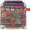
Searched around the internet for a picture of the 1227165 internals and didn't find an actual year correct version. I found a newer version I believe produced in the 90's. Some of the IC part numbers have been updated but I believe it represents the internals accurately. Does any one have a correct vintage 1227165 laying around to take a peek inside?

1227165_PCB.jpg
 
Last edited:
Yep, look at the bottom of my third post above. That about the only consolidated source of info I have been able to find. Good stuff!!
 
I did some research on the AFR learning capability of the ECM. Below is a compilation of info I gathered from multiple sources. Warning it’s a long post. My next post will cover more MAF specific stuff and the LV8 calculation and use within the fueling algorithm. More to come.


Integrator and Block Learn Multiplier (INT and BLM):
The ECM controls the fuel injectors by using signals from the engine sensors, like TPS, MAF, RPM, ECT, and others, to pick out the right value from the right lookup table to use in the fuel injector pulsewidth calculation. The ECM injector pulsewidth calculation also uses the INT and BLM ‘correction’ factors based on O2 sensor feedback when it is in closed loop. O2 sensor correction is not used in open loop. Note that there are 2 kinds of open loop. Right after a cold or hot start, a scan tool will report that the ECM is using open loop fuel control. This version of open loop is described in the next section. Once the ECM decides that conditions are right, it switches to closed loop fuel control, which is described below the open loop discussion. But even after this switch, if you lean on the throttle hard enough, the ECM will switch to power enrichment (PE) mode, which is another form of open loop. In PE mode the scan tool may report that the ECM is in closed loop, but it should also report that learning is disabled. Learning disabled means that the ECM is ignoring the O2 sensors, which is the same as saying that the ECM is using a version of open loop fuel control.

Open loop:
When you fire the beast up, whether the engine is stone cold or fully warmed up, the ECM starts out in open loop. This is because cold (or just warm) O2 sensors don't work very well, and they take a little while to get good and hot. Also, cold engines are happier when they are run richer than the fixed closed loop air/fuel ratio target. Since the O2 sensor signal is not reliable right after the engine is started, the ECM has no way to find out whether the engine is running too rich, too lean, or about right. But it still needs to take a stab at the right injector pulsewidth.

When the engine is running in open loop at light to moderate loads (idling, city driving, highway cruising), the ECM uses various table for the pulsewidth calculation. The table uses the ECT (colder engines need to be richer than warm engines) and MAF (higher loads require a richer mix than light loads) sensor inputs to point to the desired AFR for those temperature and load conditions. As always, the MAF sensor tells the ECM how much air the engine is inhaling. The ECM knows how big the injectors are (the amount of fuel is delivered per millisecond of pulsewidth), so with the MAF sensor output (the amount of air inhaled by the engine) and the correct base pulsewidth from the table (the desired air/fuel ratio), it can estimate its best-guess injector pulsewidth. Remember that the ECM has no idea whether or not this guess-timated pulsewidth is anywhere near right. It could be causing the engine to be very rich, or very lean, or anywhere in between.

Remember that engines like a richer air/fuel mixture when they are cold (richer than the fixed 14.7:1 ratio used in closed loop), and when they are asked to make more than just a cruising level of power. So the AFR table values for high MAF (heavy load) and low ECT (cold engine) are lower (richer) than the values for low MAF and normal operating ECT. This means that "cold engine enrichment" and a bit of "power enrichment" are built right in to the table. This quasi-power enrichment may be used in open loop when you maintain your freeway speed up a steep hill in high gear. But see the last section on this page for what happens when you really lean on the throttle.
When is the engine ready to switch from open loop to closed loop? The current theory is that the ECM decides to switch based on some combination of ECT and engine running time (3 minutes?).

Closed loop:
When the engine temperature and time-since-the-engine-started timer agree that the O2 sensors are warmed up and ready, the ECM switches to closed loop (at least this how I think it works). Just as it did for open loop, the ECM calculates the closed loop base pulsewidth using numbers programmed in lookup tables.

While the target open loop air/fuel ratios are contained in the AFR table, the closed loop air/fuel ratio is hard-coded in the ECM to be 14.7:1. The MAF sensor tell the ECM how much air the engine is inhaling, the injector constant and injector-offset vs. voltage values tell the ECM how much fuel the injector will flow for any particular pulsewidth, so the ECM just does the math to calculate the appropriate injector pulsewidth. Well, it may be a bit more complicated than that...
Even in closed loop, the injector pulsewidth calculation is really just a guess based on the MAF sensor, the injector constant and offset. If the pulsewidth is not right, the fuel/air mixture will be too rich or too lean. It's very important to remember that the ECM tries to keep the AFR at the "ideal" ratio of 14.7 while it's in closed loop. This is where the O2 sensors come in. The O2 sensor generates an electrical signal for the ECM that represents the amount of oxygen in the exhaust stream, which is proportional to the air/fuel ratio. This signal, which is the feedback that "closes the loop", tells the ECM how good a job it's doing on the fuel mixture. The ECM uses this feedback to calculate a correction number, sometimes called the integrator, or INT for short, or the short term fuel offset. The ECM uses the short term fuel offset to adjust the pulsewidth calculation so that the air/fuel ratio homes in on 14.7:1. Plus, and this is important, it stores the offset so it can be used later.

The O2 sensor cross count is incremented every time the O2 sensor switches from rich to lean and vice versa. It's only an 8-bit value, so it counts up to 255 and then rolls over to zero and starts over. If it's constantly increasing then that means that the ECM is controlling the AFR. The ECM richens the mixture and then waits for the O2 sensor to report a rich mixture. Once it does the ECM leans out the mixture and then waits for the O2 sensor to report a lean mixture. This process (switching back and forth between rich and lean) goes on continuously while the engine is running. It has to do it this way because there is no way the ECM can hold the AFR in the center of the O2 sensor curve.

INT & BLM = Learning:
The integrator and Block Learn Mode (BLM) are at the heart of the ECM fueling learning process. In a nutshell, the Block Learn Multiplier (BLM) is the long term fuel adjustment that the ECM "learns" to keep the air/fuel ratio within acceptable parameters. The Integrator is the same idea, only for short term adjustments. Basically, these two strategies are used to make adjustments and adaptations to the ever changing loads, atmospheric conditions, and fuel quality to keep the car's air/fuel ratio correct for driveability and emissions.

Also, keep in mind that when we say Long Term or Short Term, we are talking in computer time, not human time. In our ECM the Long Term fuel adjustment (BLM) happens about twice per second, while the Short Term fuel adjustment (INT) happens about 20 times per secondhen you do an ECM reset it sets all the BLM cells to a default value (on my car it's 120). If you look at the BLM chart you will see that it is virtually impossible to get into the "corner" cells (3 & 12). Take cell 12 for example: you can't have an airflow of over 34 gm/sec at less than 700 RPM. Basically airflow increases with RPM, so you'll find the engine spends most its time in the cells on the diagonal: 0, 5, 10, 15.

About the INT:
This gets kind of complex... Background info for you to help you understand what's going on. [This all applies to my antique 1227165 ECM -- the newer ones are faster and other things are improved.] the ECM keeps a running average of the O2 sensor voltage. It takes an O2 sensor reading, throws away the oldest of three readings and adds the new reading and then averages the three values to get a new value. It calculates the INT from that value. Now the ECM compares the INT to the value in the current BLM cell. Things start to get a little complex here... ;-) The ECM does what is known as a "lag filter" on the BLM cell value. What that means is that it adjusts it based on how far away from the BLM cell value the INT is. If it's pretty close it doesn't change. If it's a little farther away it changes the BLM a little. If the INT is really far away it changes it a lot. The change amount is proportional to the difference between the INT and the BLM.

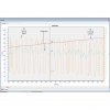
All of the above is necessary because of what comes out of the O2 sensor. Here's a pic of the O2 sensor voltage from my car at idle. Each vertical line is 1/2 second apart and each horizontal line is 200 mV apart. Zero volts is where the little arrow on the left is. The signal varies between about 200 mV and 800 mV. Below you can see the Integrator value as well tracking along with the O2 sensor signal both oscillating back and forth. The O2 cross count can also be seen increasing.

Drawing1.jpg


This is why the INT jumps all over the place -- it's calculated from the O2 sensor voltage. The above is at idle. You can imagine what happens while you're driving, shifting, etc. That's why the ECM just gives up at WOT and goes open loop -- it can't keep up because the changes in the engine sensors are happening too fast and are too great.

About BLMs:
On my car the BLMs are constrained to a low limit of 108 and a high limit of 160. If the BLM hits the limit then the ECM just stops adjusting it and holds it at the limit. This prevents the AFR from getting too far out for the engine to run. It's a failsafe mechanism to keep the engine running even if the ECM is getting faulty sensor data.

About "128":
This is the "ideal" BLM for gasoline at 14.7 AFR. If you're running 10% ethanol (which the engineers who designed this system never heard of) then the ideal AFR is 14.5 and the ideal BLM will be a little different. 128 is just a number. It doesn't mean anything special by itself. The main thing is that you don't want to hit the limits. It's nice to get the BLMs near 128 because it gives the ECM more room to adjust the AFR, but not absolutely necessary.


The BLM table and cells:
The fuel delivery strategy uses a two dimensional table that has four rows and four columns, for a total of 16 "cells". Each cell contains a Block Learn Multiplier (BLM) value (from 0 to 255), which represents a long-term fuel correction based on that cell's operating conditions over a relatively long period of time. Each BLM value in turn contains an integrator value (also from 0 to 255), which is a short term fuel correction based on immediate operating conditions. For both the Integrator and BLM values, a higher value represents a correction that adds fuel to the fuel mixture, due to higher injector pulse widths.


The table above depicts the BLM cell table that is held in the typical TPI MAF ECM. As you can see, it is offset by rpm in the columns, and by airflow in the rows. The individual cells are numbered 0 through 15 (for a total of 16 cells). So, the cell being accessed at any given point in time is controlled by airflow versus rpm. The numbers in red are the actual BLM values in my car.

table1.jpg

Let's take a few "for instances". Let's say the car is sitting in the driveway in Park, up to temperature, and just idling. In that case:
• RPM = 750
• MAF = 6

Since the RPM is very low and the MAF is very low, the car will be using the information in BLM Cell 0 to adjust the idle fuel mixture. The value contained in that cell is adjusted with the Integrator values (which change based on O2 readings, etc.).

Now, let’s go for a typical highway cruise, at about 65mph, on a nice flat road:
• RPM = 1800
• MAF = 22

Since the RPM is above the highest value in the column to the right, and the MAF is reading a value in the “third” row, we can see that the ECM is now accessing, and using the BLM value in cell 6. Cruise conditions will often move between cells 6 and 10 based on small changes in MAF, since the typical highway cruise value is between 15 and 25.

Typically when you pull away from a stop sign or traffic light in fairly normal circumstances, you’ll see that it takes only a second or so for the RPM to jump over the 1500 upper RPM limit, and the MAF (air flow) will very easily jump up over the 30 gps upper MAF limit. In this example the ECM will be using cell 15 (sometimes erroneously called the WOT cell) (WOT meaning Wide Open Throttle).

What does the BLM do:
The BLM is a long term adjustment, which is stored pretty much permanently (unless you disconnect power to the ECM), to the fuel delivery calibration that results from the ECM "learning" the values while you are driving around. 128 is the ideal value, because it is the center point of the range 0-255. Above 128, and the ECM is adding fuel to compensate for a lean condition at a particular load and RPM. Below 128, and it represents a correction for a rich condition.

How does the Integrator play into this:
On a cold start the INT is set to 128 and kept there until the coolant reaches a threshold value, a timer says the engine has been running long enough, and the O2 sensor has warmed up and started responding. The ECM then sets the closed loop flag, which means that if other conditions are met (not in PE, DE, or DEFCO modes, primarily) the ECM uses the O2 sensor to control the INT. It adds to the INT in small increments until the O2 voltage goes above a threshold so the ECM knows the engine is now rich, then it starts subtracting from the INT until the O2 voltage goes below another threshold and the engine is lean. The ECM keeps cycling the INT, trying to keep the time spent rich equal to the time spent lean so it knows that the average is stoichiometric. If other conditions are met then the learn control flag is set and the ECM keeps a moving average of the INT values. If this average is not 128, it will add or subtract to the current BLM value to move the INT average towards 128. This is done a few times a second, without the INT ever having to get to an extreme value such as 90 or 150. The stock BLM range is 105 to 150, but even if the BLM has reached one of these limits the ECM is still able to keep the engine averaging stoichiometric so long as the INT is not also at a limit. For example, the BLM could be 150 and the INT ranging between 135 and 145.

If you have a scan tool or Direct Scan you can watch this process. The ALDL update rate will keep you from seeing all of the INT values but you will still see the long-term trends. Start the engine and let it warm up so that learn mode is enabled, then pull the vacuum hose off of the fuel pressure regulator. The fuel pressure will jump up 4-7 psi and the engine will go rich. The INT will drop below 128 and go down until the engine finally goes lean or a limit is reached, and will then go up and down over a range of maybe 10-20 units as the ECM keeps the engine bouncing between rich and lean, and the BLM will start dropping. As it does, the average INT will rise back to 128. Once the INT average is 128 the BLM will stop changing. Put the vacuum hose back on, the fuel pressure will drop, the engine will go lean, and the mirror image of the above will occur. The INT will rise, start bouncing up and down, the BLM will rise, and the INT average will eventually reach 128 and the BLM will stop changing again.

Summary:
BLM values are divided in to "Cells" based on MAF vs. RPM. Within each cell, there typically values from 105-150 for the BLM. Within the BLM value, there are Integrator values, typically 105-150 also. The Integrator is adjusted based on sensor feedback (primarily the O2 sensor) to make real time adjustments for varying conditions. If the adjustments cannot be made in a BLM value, then the BLM value is either increased (add fuel) or decreased (subract fuel) to compensate.
If you reach the "corner" of an individual cell and not further adjustment is possible, the car may not run correctly and there is a problem with the calibration or a critical sensor.

It all sounds very intimidating, but really isn’t. One must keep in mind that the changes that are being made, as in the INT for example it is happening at close to 20 times per second. Think of it this way; The INT is used to “drive” the BLM number toward a value needed to maintain stoiceometric A/F ratio. As in one of the examples above, make a radical change (such as removing the fuel pressure regulator’s hose) and watch the INT do it’s thing!! The INT will jump to a high value, and hover there while the BLM starts its “march” up the scale. As the BLM approaches the value needed to get the A/F ratio corrected you’ll see the INT value heading back down toward 128. Ideally, they will both meet at 128 at about the same time. It’s really neat stuff to watch.
 
Last edited:
Here’s the next installment. MAF functionality, how does the ECM convert the 0-5 volt signal the MAF generates based on air flow to something the ECM can use in its fueling and timing calculations? Also related, what the heck is LV8? (Engine Load Variable)

MAF and LV8, two important elements to understand in a MAF based engine:

Here a summary of my understanding of how the Mass Air Flow (MAF) sensor info is used in the 1227165 ECM and how engine load is determined based on MAF. This is a compilation of info I have researched on the web.

The MAF based engine control system utilizes the Mass Air Flow sensor for its primary fueling routines. The ecm assumes that a set mass of air will equate to a specific requirement of fuel, based on the ecm’s coded air/fuel ratio, based on multiple terms and load conditions.

The Mass Air Flow device in this application utilizes a hot wire element to create a transfer function based upon the relationship of current flow though the element (temperature rise) to airflow (cooling effect of airflow). As the airflow increases, more current through the element is required to maintain a set temperature. This current change is converted to a voltage range of nominally ~0-5 Volts full scale in this particular sensor. This relationship of heating to current flow is known as King’s Law. The formula(s) is available on the internet if more technical detail is of interest.

One item to note is that the MAF sensor measures effective cooling of a heated wire, so in reality, humidity will also affect the MAF voltage reading. The tune should not vary greatly due to this (this depends on engine modifications, and how tightly the engine is tuned), but if you encounter weird engine operation, and can account for large changes in humidity, this may be responsible. This is one of the downfalls of this type of load measurement device.

The typical response curve of the MAF sensor used with the 1227165 ecm is as below. Notice it not a linear curve so how does the ECM deal with this?
This airflow curve is literally reconstructed based on the transfer function in the actual ecm code using tables and scalars.

MAFcurve.jpg


MAF TABLES and SCALARS
The ecm works within an 8 bit word limit (in most cases), and as such, you can see that the airflow in grams per second conveniently ends at 254 for the last few entries in the curve. 2^8=256: Using a 0 based numbering system, the max number is 255, the above table ends at 254 due to the conversion math. This happened to be a matter of convenience, and it should be reinforced that these tables are merely a transfer function, more plainly put, there is nothing written is stone that this system is limited to 255 grams per sec. It could easily have been written to be 255 units per second, where each unit was 2 grams, but resolution is lost.

In order to gain even better resolution, this coding scheme utilizes 2 dimensional tables along with scalar multipliers to efficiently model this curve while minimizing code space. This table is stored in the read only memory. The table consists of the scalar, table value and MAF volts. So the ECM looks up the value based on MAF volts and returns that value to the ECM for various calculations.

Here’s the table representation. Remember the table only includes the scalar, MAF volts and table value. The Grams/Sec is a calculated value based on this info. This basically recreates the MAF curve above accurately in the ECM. In the MAF airflow chart, you can see how the curve is nice and smooth. This is because the tables are carefully calculated to provide seamless transitions from one table to the next. Since the tables are made using a scalar multiplier, it is important to realize that if you need to tweak a table at the last entry, that you affect both the table, the scalar, and the next table and its scalar. Below is a chart that shows the airflow in grams per second in the same manner as the ecm would calculate. You’ll notice that the last value in each column and the first value of the next column match very closely.

MAF Tables stores in the ECM read only memory.

The math works as follows.

There are 6 MAF tables. Each MAF table has an associated Scalar value.

The ECM multiples the Scalar value by the table values to determine the conversion from volts to grams/sec.

formula programmed in the ECM for this is >> (MAF Table Value*Scalar for table)/255= Grams/Sec airflow <<

Example: Lets say the MAF is measuring airflow and providing 0.55V
to the ECU. The ECU does a table lookup on the MAF voltage and
returns the table value of 69.

The table value of 69 is multiplied by the scalar value of 23
for table 1. Then divided by 255 for a Grams/Sec value of 6.2
---------- (69*23)/255 = 6.2

Remember, the table only includes the table value and MAF voltage data points. The actual Grams/Sec is calculated based on these two items and used if multiple functions within the ECM like main fueling calculation.


Here's the MAF table:
;------------------------;
; Mass Air Flow TABLE 1 ;
; ;
; TABLE = gm/sec * 11.1 ;
;------------------------;
23 ; TABLE SCALAR
;-----------------
; VDC gm/sec
Value;-----------------
0 ; 0.00 0.0
36 ; 0.18 3.2
50 ; 0.37 4.5
69 ; 0.55 6.2
93 ; 0.73 8.4
121 ; 0.91 10.9
155 ; 1.10 14.0
197 ; 1.28 17.7
248 ; 1.46 22.3

;------------------------;
; Mass Air Flow TABLE 2 ;
; ;
; TABLE = gm/sec * 5.33 ;
;------------------------;
48 ; TABLE SCALAR
;----------------
; VDC gm/sec
Value;----------------
119 ; 1.46 22.3
133 ; 1.55 25.0
147 ; 1.65 27.6
163 ; 1.74 30.6
180 ; 1.83 33.8
198 ; 1.92 37.1
217 ; 2.01 40.7
237 ; 2.10 44.5
254 ; 2.19 47.7

;------------------------;
; Mass Air Flow TABLE 3 ;
; ;
; TABLE = gm/sec * 3.08 ;
;------------------------;
83 ; TABLE SCALAR
;--------------
; VDC gm/sec
Value;----------------
147 ; 2.19 47.7
158 ; 2.29 51.2
170 ; 2.38 55.1
182 ; 2.47 59.0
195 ; 2.56 63.2
209 ; 2.65 67.8
223 ; 2.74 72.3
238 ; 2.83 77.2
253 ; 2.93 82.0

;-----------------------;
; Mass Air Flow TABLE 4 ;
; ;
; TABLE = 1.90 * gm/sec ;
;-----------------------;
135 ; TABLE SCALAR
;----------------
; VDC gm/sec
Value;----------------
156 ; 2.93 82.3
166 ; 3.02 87.5
176 ; 3.11 92.8
187 ; 3.20 98.6
198 ; 3.29 104.4
210 ; 3.38 110.7
222 ; 3.47 117.1
237 ; 3.57 125.0
255 ; 3.66 134.5

;-----------------------;
; Mass Air Flow TABLE 5 ;
; ;
; TABLE = 1.24 * gm/sec ;
;-----------------------;
207 ; TABLE SCALAR
;-----------------
; VDC gm/sec
Value;-----------------
166 ; 3.66 134.2
176 ; 3.75 142.3
186 ; 3.84 150.4
196 ; 3.93 158.5
207 ; 4.02 167.4
219 ; 4.11 177.1
230 ; 4.21 186.0
242 ; 4.30 195.7
255 ; 4.39 206.2

;-----------------------;
; Mass Air Flow TABLE 6 ;
; ;
; TABLE = 1.00 * gm/sec ;
;-----------------------;
255 ; TABLE SCALAR
;-----------------
; VDC gm/sec
Value;-----------------
207 ; 4.39 206.2
213 ; 4.43 212.2
219 ; 4.48 218.1
226 ; 4.53 225.1
233 ; 4.57 232.1
240 ; 4.62 239.1
248 ; 4.66 247.0
255 ; 4.71 254.0
255 ; 4.75 254.0
255 ; 4.80 254.0
255 ; 4.85 254.0
255 ; 4.89 254.0
255 ; 4.94 254.0
255 ; 4.98 254.0
255 ; 5.03 254.0
255 ; 5.07 254.0
255 ; 5.12 254.0


What happens if the MAF voltage signal doesn’t fall directly on a table value?

Example:
Lest say the MAF is putting out 1.49 volts. As you can see below this falls in between the 1.46 and 1.55 entries in the MAF table. How does the ECM deal with this? It uses an interpolation function to calculate the exact table value that would correspond to 1.49 volts. All the tables in the ECM are handheld this way. This makes for a very efficient use of memory. We will save this detail for another detailed discussion on how this works.

Value VDC gm/sec
------------------------
119____1.46__22.3
133____1.55__25.0


LV8 What is it:

The grams/sec value calculated above is then used to determine the load, based on RPM, called LV8: Load Variable (8 bit).

LV8 = (MAF cell value/256) X RPM X LV8 Constant X (MAF Table Constant/256)

From looking at the ECM code, RPM is actually the crank reference, so it's converted, but essentially it's an RPM type value.

Since we are dealing with a MAF engine vs. a MAP (Manifold Air Pressure) / speed density engine. The LV8 calculation is a way to determine engine load based on MAF and RPM.

In a speed density/MAP engine air flowing into an engine is estimated using engine displacement and a volumetric efficiency (VE) table which is indexed by RPM and manifold absolute pressure.

In a MAF engine, we are measuring the actual amount of air entering the engine. This simplifies the math to some extent. This is where the LV8 comes in. The LV8 basically replaces the functionality of the MAP/VE tables in a speed density based engine. The LV8 provides the MAF based engine a ‘load’ variable.

So the calculated LV8 number is using MAF and engine RPM to drive it. It works pretty good at low loads... it looks as if it is used to determine "gross timing and fueling" before the various trims/PEs and such kick in.

From notes I found:
- LV8 is used in for determining EGR duty cycle (and I believe charcoal canister purge too?)
- In conjunction with coolant temp and open loop, it enriches cold start conditions
- It is a primary driver for determining Power Enrichment (PE) in conjunction with TPS
- LV8 <25 will disable "Learn" mode
- LV8 is a main parameter for timing
- It is used for decel fueling (reduces fueling) and for DFCO (decel fuel cut off) in conjunction with TPS


Here’s the formula used in the ECM
Load Variable (8 Bit) = airflow*scale factor*inverse RPM factor

Example:
LV8 = (gms/sec/ 256) * (Scale factor / 64)*(Distributor Ref Pulse Count)

For an engine at 3000 RPM and an airflow of 90 gms/sec with a scalar of 80:

LV8 = (90/ 256) *(80 / 64) * (328)

LV8 = 144

The Distributor Reference Pulse Count value is determined by the internal 16 bit pulse counter. 2^16=65536 bit counts per second. 65536 multiplied by some time/4 stroke conversions gives you the formula for an 8 cylinder application:

DRP=983040/rpm


This is the term used the equation above (328). For 4 and 6 cylinder the constant 983040 changes.

The Scale factor of 80 is hard coded in the firmware, and could be calibration specific. For 32, 32B and 6E masks, the factor is 80.

This LV8 term is then used for all load calculations.

It’s important to understand the relationship between all of these terms. Changing the MAF tables will ultimately affect a lot of operating parameters, so subtle tweaks to improve your fueling is OK, but large changes should only be attempted by those with lab grade equipment that can be used to recalibrate the intake system (no average backyard tuner)

The MAF system is effective in it’s simple relationship between airflow to required fuel. If X amount of air is flowing, Y amount of fuel is needed. Because of this, you will not see any parameters dealing with engine displacement, since it will always try to maintain 14.7:1 AFR in closed loop (Non Power Enrichment) based solely on airflow.
 
Last edited:
I just read a book on gm fuel injection so this is a nice refresher course for me to read. I may also recomend a good book by greg banish which is Engine Management Advanced Tuning good info though!!! ;)
 
Strictly Attitude said:
I just read a book on gm fuel injection

What GM fuel injection did you read? There's a few of the out there and I'm always looking for a good read.
 
Table Lookup & Interpolation

As mentioned in the MAF post, the ECM uses an interpolation subroutine for just about all of it’s table lookup functions. Why? Well it would be very inefficient to build table with entries at every possible data point. Think how big these tables would be and how much memory they would take up. The ECM in the 80’s had very small memory space available. The ECM used a single interpolation subroutine formula for all it’s table lookups.

Using the example from the MAF post:
Lest say the MAF is putting out 1.49 volts. As you can see below this falls in between the 1.46 and 1.55 entries in the MAF table. How does the ECM deal with this? It uses an interpolation function to calculate the exact table value that would correspond to 1.49 volts. All the tables in the ECM are handheld this way. This makes for a very efficient use of memory.


Value VDC gm/sec
------------------------
119____1.46__22.3
133____1.55__25.0


This writup from the ThirdGen.org forum describes how GM's 2D and 3D table lookups operate.
http://www.thirdgen.org/forums/diy-prom/175570-table-lookups-introduction.html


These tables would include the timing table, the knock retard tables, the VE table, MAF scalar tables, TCC tables, and a host of others. A 2D table is a one dimensional array of values while the 3D table is a 2 dimensional array of values. In the P4 ECMs the maximum number of rows and columns for a table is 17.

For a 2D table a single argument (arg) is used to locate the proper value within the table. A 3D table has 2 arg's in order to locate the proper value within the table. The value of the argument can span from 0 to 255, a single byte value. Most of the time the arg value does not fall directly on a row or a row/column intersect. Because of this the lookup routine interpolates between the row & column table values.

The arg terms may be any number of different sensor or internal values. Some common ones are RPM, CTS, TPS, AFR, MAP, MAF, battery voltage, and knock counts.

A 2D table of 17 rows is the easiest to understand. It is used in the following example. With 17 rows there are 16 steps and 16 arg increments between each row. This 16 * 16 = 256.

Bascially speaking the ECM code will do a 16 point interpolation between the rows.

Here is our example 2D table:

Code:
;--------------------------------------
; XYZ ; rpm
;--------------------------------------
XYA: FCB 70 ; 0
FCB 65 ; 400
FCB 69 ; 800
FCB 69 ; 1200
FCB 71 ; 1600
FCB 91 ; 2000
FCB 102 ; 2400
FCB 122 ; 2800
FCB 127 ; 3200
FCB 132 ; 3600
FCB 133 ; 4000
FCB 164 ; 4400
FCB 185 ; 4800
FCB 196 ; 5200
FCB 205 ; 5600
FCB 245 ; 6000
FCB 255 ; 6375

The lookup arg is RPM. In this case the ECM value for RPM is RPM / 25. So an RPM of 2450 is: 2450 / 25 = 98, the 98 being the value that the ECM uses internally for that RPM.

Note how the table rows are labeled, starting at 0 RPM, then the next row being 400 RPM, the next being 800 RPM. There is a 400 RPM difference from row to row.

This is because of the 16 arg increments between each row:
16 * 25(rpm per increment) = 400(rpm between each row).

Staying with 2450 RPM what is the looked up value?

First divide the 98 (2450 / 25) by 16: 98 / 16 = 6.125, with the ECM keeping 6 (no fractions allowed, although the code will round to one place: 10.6 becomes 11).

1) Multiply 16 * 6 for a 96 and subtract that from 98 (the arg) for a 2.

2) Go to row 6 and get the value 102 (at 2400 rpm).

3) Go to row 7 and get that value: 122 (at 2800 rpm).

4) Sub the row 7 & 6 values: 122 - 102 = 20

5) Divide 20 by 16(increments between rows): 20 / 16 = 1.25, or 1

6) Multiply the 1 * 2 (from step A): 2 * 1 = 2

7) Add the 2 (from step F) to the 6th row value of 102: 102 + 2 = 104

** 104 is the final value and is the value the lookup routine returns.

In step 1 the value of 2 means that the lookup is 2/16's of the way to the next row.


The 3D lookup routine does the exact same math three times. Once each for the two sets of rows, then once again between those values (for the column interpolation).


Now for the tricky stuff: not all tables are like the one above.

Here is a table that has been compressed:

Code:
;--------------------------------------
; XYZ ; rpm
;--------------------------------------
XYA1: FCB 8 ; row count

FCB 70 ; 0
FCB 69 ; 800
FCB 71 ; 1600
FCB 102 ; 2400
FCB 127 ; 3200
FCB 133 ; 4000
FCB 185 ; 4800
FCB 205 ; 5600
FCB 255 ; 6375

Notice how each row increments by 800 rpm. It is a 9 line table as shown by the row count (yes, they don't match and is correct). In this case the lookup routine will properly handle the table while doing a 32 point interpolation between rows.


Another case is where the table starts at at 0 RPM with a maximum of 3200 RPM:

Code:
;--------------------------------------
; XYZ ; rpm
;--------------------------------------
XYA2: FCB 70 ; 0
FCB 65 ; 400
FCB 69 ; 800
FCB 69 ; 1200
FCB 71 ; 1600
FCB 91 ; 2000
FCB 102 ; 2400
FCB 122 ; 2800
FCB 127 ; 3200

The code will first check if the RPM is over 3200 and if it is set the arg to 3200 RPM (128). The lookup routine is then called. It will do the regular 16 point interpolation.

*********************************************
*********************************************


Here’s another snippet from http://carprogrammer.com/Z28/PCM/FAQ/ECMTuningNotes.htm describing the table lookup process.

Topic: 3D table lookup

It's a 3-way, 16-point interpolation between the table values.

Think of the point of 53kpa map & 1700 rpm as being someplace inside of a box. The four corners of that box, are the four table values
that surround the defined point. The distance from that point, to each of the four walls is estimated, with the final result based on those
four values.

Works something like this...

Part of main SA table:

map> 50 60
rpm
1600 20 24
1800 22 26

If the map is 53 and the rpm is 1700, first lookup gets the 20 & 24 degree values @ 1600 rpm, and interpolates between them. The difference
between these two are divided into 16 points:

24deg - 20deg = 4deg, 4deg / 16points = .25 deg per point

60map - 50map = 10map, 10map / 16points = .625 kpa per point.

53 map @ 1600rpm => 20deg + (3map / .625) * .25 = 21.2 deg.

So, 21.2 deg is the 16 point interpolation of 53 map @ 1600 rpm.

(Note: On a 2D table, we would be done, and this value returned).

The 3D lookup, however, calls the 2D routine a total of three times. In this example, the first call we already completed.

The routine then advances a full row to interpolate between the 22 deg and 26 deg values found at 1800rpm.

So, using the same math as above, 23.2 deg is the 16 point interpolation of 53 map @ 1800 rpm.

The third and final interp. is done between the answers of the first two lookups: 21.2 deg & 23.2 degrees (@ 1600 & 1800 rpm).

The rpm is divided into 16 points the same. For this example, it's right in the middle of table values 1600rpm and 1800rpm,
with 1700 actual.

So, 21.2 deg & 23.2 deg => 22.2 deg as the actual returned, looked up finalized interpolated value to be used.

*********************************************
*********************************************


Cool stuff isn't it.. To me this is another important operational point to understand how the ECM functions. Im sure this same process is used in modern ECM's as well just that tables are larger and have better resolution.

Related Links:
Here’s a video showing the detailed explanation of table interpolation. (lots of math here)
https://www.youtube.com/watch?v=6WAeqE41-1Y

Here’s an interesting video describing how to do interpolation in Excel,
https://www.youtube.com/watch?v=LFUd5qF8nyE


From the INT/BLM discussion a few posts back. I uploaded a PowerPoint animation I put togeather that shows the INT and BLM in action the way I understand it to work.
The action starts about half way through the video.

The scenario depicted is the engine is in closed loop mode and some event caused the exhaust AFR to go lean. The INT responds immediately to compensate. After a certain amount of time in this state, the BLM will kick-in and put the INT back at 128 (short term fuel trim). The new BLM will be stored in the ECM memory and continue to adjust the AFR for that given RPM/load range or BLM cell in the future (long term fuel trim).

https://www.youtube.com/watch?v=b7yZpzaUnKA&feature=youtu.be
 
Back
Top