"The LSA, or lobe separation angle, is ground into the cam and cannot be changed. It is the angle that separates the intake and exhaust lobe for a particular cylinder, and is measured in camshaft degrees. The intake lobe centerline is measured in crankshaft degrees. most guys use the terms almost interchangably WHICH THEY ARE NOT in all cases!
LCA =(LOBE CENTER ANGLES)remember lobe center angles can be changed thru indexing the cam when degreeing it in, LSA (LOBE SEPERATION ANGLE) is ground into the cam during its manufacturing process.The #1 intake lobe centerline is usually between 100° to 110° ATDC and is what you use to degree the cam. The cam manufacturer will publish the specs for the cam based on a given intake lobe centerline. Comp Cams, for instance, produces a large number of cams with 110° LSA ground 4° advanced, so they list the specs for the cam with a 106° intake lobe centerline. You can calculate the ILC by adding the intake opening angle in °BTDC, the intake closing angle in °ABDC, plus 180° for the distance from TDC to BDC. Divide by 2 and subtract the intake opening angle and you will have the ILC. For example a 12-430-8 Comp Cam lists IO at 34°BTDC, IC at 66° ATDC, so 34 + 66 + 180 = 280. 280/2 = 140. 140 - 34 = 106° ILC
Figure 3 is a picture of both an intake and an exhaust lobe of a camshaft, seen end-on. It shows the relationship between the lobes, shows the overlap area, and illustrates this next section.
As stated in lesson 2, overlap has a great deal to do with overall engine performance. Small overlap makes low-end torque but less high-end power. Large overlap reduces low-end torque but increases high-end power.
Overlap is determined by two other cam specifications, Duration and Lobe Center Angle.
Duration is the time, measured in crankshaft degrees, that a valve is open. A duration of 204 degrees means that while the valve is open, the crankshaft rotates through 204 degrees.
Duration is measured on two "standards," "advertised duration" and "duration at 0.050"." Advertised duration is measured from when the valve just starts to lift off its seat to when it just touches the seat again. This is measured in different ways by different manufacturers. Some measure when the valve lifter is raised 0.004", some at 0.006", and some at different points yet. So the industry agreed to another standard that was supposed to make it easier to compare cams. In this standard, the duration is measured between the point where the lifter is raised by 0.050", and the point where it is lowered again to 0.050".
The 0.050" standard is great for side-by-side "catalog" comparisons between cams. But if you use engine prediction software on your computer, the software is much more accurate when you can feed it "advertised" duration numbers.
Lobe Center Angle is the distance in degrees between the centers of the lobes on the camshaft.
To increase duration, cam makers grind the lobes wider on the base circle of the cam. This makes the lobes overlap each other more, increasing overlap. More duration = more overlap.
To increase overlap without changing duration, cam makers will grind the lobes closer together, making a smaller lobe center angle. Less lobe center angle = more overlap.
Overlap and duration are the two big factors in cam design. More overlap moves the power band up in the engine's RPM range.
Longer duration keeps the valves open longer, so more air/fuel or exhaust can flow at higher speeds. It works out that increasing the duration of the camshaft by 10 degrees moves the engine's power band up by about 500 rpm.
A smaller lobe separation increases overlap, so a smaller lobe separation angle causes the engine's torque to peak early in the power band. Torque builds rapidly, peaks out, then falls off quickly. More lobe separation causes torque to build more slowly and peak later, but it is spread more evenly over the power band. So a larger lobe separation angle creates a flatter torque curve.
So you can see how a cam maker can tailor the camshaft specs to produce a particular power band in an engine--
Short duration with a wide separation angle might be best for towing, producing a strong, smooth low-end torque curve.
Long duration with a short separation angle might be suited for high-rpm drag racing, with a high-end, sharp torque peak.
Moderate duration with wide separation angle might be best suited for an all-around street performance engine, producing a longer, smoother torque band that can still breathe well at higher RPM.
Remember, there's always a compromise made in this process.
One last item to consider is the lobe centerline. The lobe centerline is the angle of the lobe's center peak, measured in crankshaft degrees when the piston is at Top Dead Center (TDC). In general (but not always), when a cam is installed "straight up," the intake lobe centerline and the lobe separation angle are the same.
The lobe centerline can be altered when the camshaft is installed, by advancing or retarding the camshaft's position in relation to the crankshaft. Advancing the camshaft by 4 degrees will move the power band about 200 RPM lower in the RPM band. Retarding the cam by 4 degrees will likewise move the power band 200 RPM higher in the RPM band. This allows you to fine-tune the engine's performance according to your needs.
personally I try to stay close to 106- 110 degrees on most carb engines and 112-114 degrees on EFI engines because I value a wider torque curve more than a few hp only close to peak rpm, and there tends to be fewer low rpm tunning issues with efi vs carbs that way
on the better 23 degree SMALL BLOCK AFTERMARKET HEADS THERE'S ABOUT 5.5 INCHES OF INTAKE PORT LENGTH ON AVERAGE FROM INTAKE GASKET TO THE BACK OF THE INTAKE VALVE AT THE FAR EDGE
http://www.compcams.com/Technical/TimingTutorial/

viewtopic.php?f=52&t=1070&p=4829#p4829
viewtopic.php?f=52&t=2782
http://www.wighat.com/fcr3/confusion.htm
http://www.idavette.net/hib/camcon.htm
http://www.babcox.com/editorial/ar/ar119736.htm
http://home.wxs.nl/~meine119/tech/camqa.html
http://tru-442.tripod.com/camselect.htm
be aware that some crank gears have more than one index slot to index to the crank key and each slot is marked and you must use the correct matching marks indicating (ZERO) that match the crank slot marks
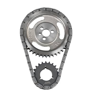
look closely SLOT A uses a different TDC mark (A) than slot (R), which has its own TDC mark(R)
LCA =(LOBE CENTER ANGLES)remember lobe center angles can be changed thru indexing the cam when degreeing it in, LSA (LOBE SEPERATION ANGLE) is ground into the cam during its manufacturing process.The #1 intake lobe centerline is usually between 100° to 110° ATDC and is what you use to degree the cam. The cam manufacturer will publish the specs for the cam based on a given intake lobe centerline. Comp Cams, for instance, produces a large number of cams with 110° LSA ground 4° advanced, so they list the specs for the cam with a 106° intake lobe centerline. You can calculate the ILC by adding the intake opening angle in °BTDC, the intake closing angle in °ABDC, plus 180° for the distance from TDC to BDC. Divide by 2 and subtract the intake opening angle and you will have the ILC. For example a 12-430-8 Comp Cam lists IO at 34°BTDC, IC at 66° ATDC, so 34 + 66 + 180 = 280. 280/2 = 140. 140 - 34 = 106° ILC
Figure 3 is a picture of both an intake and an exhaust lobe of a camshaft, seen end-on. It shows the relationship between the lobes, shows the overlap area, and illustrates this next section.
As stated in lesson 2, overlap has a great deal to do with overall engine performance. Small overlap makes low-end torque but less high-end power. Large overlap reduces low-end torque but increases high-end power.
Overlap is determined by two other cam specifications, Duration and Lobe Center Angle.
Duration is the time, measured in crankshaft degrees, that a valve is open. A duration of 204 degrees means that while the valve is open, the crankshaft rotates through 204 degrees.
Duration is measured on two "standards," "advertised duration" and "duration at 0.050"." Advertised duration is measured from when the valve just starts to lift off its seat to when it just touches the seat again. This is measured in different ways by different manufacturers. Some measure when the valve lifter is raised 0.004", some at 0.006", and some at different points yet. So the industry agreed to another standard that was supposed to make it easier to compare cams. In this standard, the duration is measured between the point where the lifter is raised by 0.050", and the point where it is lowered again to 0.050".
The 0.050" standard is great for side-by-side "catalog" comparisons between cams. But if you use engine prediction software on your computer, the software is much more accurate when you can feed it "advertised" duration numbers.
Lobe Center Angle is the distance in degrees between the centers of the lobes on the camshaft.
To increase duration, cam makers grind the lobes wider on the base circle of the cam. This makes the lobes overlap each other more, increasing overlap. More duration = more overlap.
To increase overlap without changing duration, cam makers will grind the lobes closer together, making a smaller lobe center angle. Less lobe center angle = more overlap.
Overlap and duration are the two big factors in cam design. More overlap moves the power band up in the engine's RPM range.
Longer duration keeps the valves open longer, so more air/fuel or exhaust can flow at higher speeds. It works out that increasing the duration of the camshaft by 10 degrees moves the engine's power band up by about 500 rpm.
A smaller lobe separation increases overlap, so a smaller lobe separation angle causes the engine's torque to peak early in the power band. Torque builds rapidly, peaks out, then falls off quickly. More lobe separation causes torque to build more slowly and peak later, but it is spread more evenly over the power band. So a larger lobe separation angle creates a flatter torque curve.
So you can see how a cam maker can tailor the camshaft specs to produce a particular power band in an engine--
Short duration with a wide separation angle might be best for towing, producing a strong, smooth low-end torque curve.
Long duration with a short separation angle might be suited for high-rpm drag racing, with a high-end, sharp torque peak.
Moderate duration with wide separation angle might be best suited for an all-around street performance engine, producing a longer, smoother torque band that can still breathe well at higher RPM.
Remember, there's always a compromise made in this process.
One last item to consider is the lobe centerline. The lobe centerline is the angle of the lobe's center peak, measured in crankshaft degrees when the piston is at Top Dead Center (TDC). In general (but not always), when a cam is installed "straight up," the intake lobe centerline and the lobe separation angle are the same.
The lobe centerline can be altered when the camshaft is installed, by advancing or retarding the camshaft's position in relation to the crankshaft. Advancing the camshaft by 4 degrees will move the power band about 200 RPM lower in the RPM band. Retarding the cam by 4 degrees will likewise move the power band 200 RPM higher in the RPM band. This allows you to fine-tune the engine's performance according to your needs.
personally I try to stay close to 106- 110 degrees on most carb engines and 112-114 degrees on EFI engines because I value a wider torque curve more than a few hp only close to peak rpm, and there tends to be fewer low rpm tunning issues with efi vs carbs that way
on the better 23 degree SMALL BLOCK AFTERMARKET HEADS THERE'S ABOUT 5.5 INCHES OF INTAKE PORT LENGTH ON AVERAGE FROM INTAKE GASKET TO THE BACK OF THE INTAKE VALVE AT THE FAR EDGE
http://www.compcams.com/Technical/TimingTutorial/
viewtopic.php?f=52&t=1070&p=4829#p4829
viewtopic.php?f=52&t=2782
http://www.wighat.com/fcr3/confusion.htm
http://www.idavette.net/hib/camcon.htm
http://www.babcox.com/editorial/ar/ar119736.htm
http://home.wxs.nl/~meine119/tech/camqa.html
http://tru-442.tripod.com/camselect.htm
be aware that some crank gears have more than one index slot to index to the crank key and each slot is marked and you must use the correct matching marks indicating (ZERO) that match the crank slot marks
look closely SLOT A uses a different TDC mark (A) than slot (R), which has its own TDC mark(R)