You are using an out of date browser. It may not display this or other websites correctly.
You should upgrade or use an alternative browser.
You should upgrade or use an alternative browser.
Electrical Wiring for a TBucket
- Thread starter Indycars
- Start date
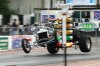
and that T-BUCKET ,cars frame thats shown jumping off the pavement and its suspension obviously need a great deal of improvement!
a properly set up cars suspension,with a decent engine and power to weight ratio,mated to high traction tires,and an experienced driver, allows a predictable and totally controlled launch WITHOUT frame twisting gymnastics and potential lack of directional stability and total predictability

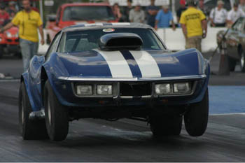

a properly set up cars suspension,with a decent engine and power to weight ratio,mated to high traction tires,and an experienced driver, allows a predictable and totally controlled launch WITHOUT frame twisting gymnastics and potential lack of directional stability and total predictability
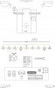
These two drawings were actually my first two drawings when I started planning
this project. The drawing below shows everything under the seat and is drawn to
scale. This helped me to decided to remove part of the two vertical braces shown
in the drawing.
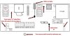
I'm switching gears now and trying to go from the theoretical to the physical part
of the project. It's one thing to have it on paper, but now I have to actual run
wires and make physical connection. The drawing below tries to show where parts
are located in a general sense so I know how many wires to run to each location.
Attachments
all I can say is your skill at posting diagrams, posting clear photography and explaining the process are exceptional, I wish I had 10% of your skills in that area
https://www.rbracing-rsr.com/wiring_ecu.html
https://www.rbracing-rsr.com/wiring_ecu.html
Last edited by a moderator:
It's a matter of how much time you want to spend doing something. The more
time the better you get, but the biggest gains come early and tapper off.
Grumpy, if you would spend a couple of hours just playing with Visio, you wouldn't
have arrows with squiggly lines and funny looking circles. There is a lot that can be
done with lines, circles and rectangles in Visio. Watch a YouTube video, then try
some of the same operations, it will start to come to you.
bytor
Well-Known Member
I noticed the fuel pressure sensor in you diagram and realized you are planing on wiring up a fuel pressure gauge. Are you intending to also connect the fuel pressure signal to your AQ-1 data logger? I ran a fuel pressure sensor on my LM-2 setup and found it helpful to see what the fuel pressure is doing while logging AFR.
Visio is a great tool. I started using it at work years ago. It has come a long way since then. You diagrams look great Rick!
Visio is a great tool. I started using it at work years ago. It has come a long way since then. You diagrams look great Rick!
Yes I will be logging the fuel pressure.
I can log up to eight external channels and possibly speed from my SpeedHut
speedometer. So I will be logging Water Temp, Oil Temp, Trans Temp, Oil Pressure,
Fuel Pressure, AFR, Acceleration and Battery Voltage, I've been on the SpeedHut
forum trying to figure out if I use the cruise control output for speed. I had an
extra wire added and it outputs a 5 volt square wave at 4000 pulses/mile for a
cruise control system.
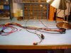
The AQ-1 wiring harness has alot of extra wires that I will never use on the
TBucket. So I decided to remove three cables or about 9 different wires and
two large connectors to simplify the harness.
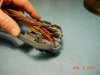
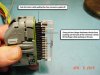
First I had to open the clam shell with a small screw driver by unlatching the
three tangs.
As you can see the AQ-1 has a good size harness that is not welcome in the
small area I have under the seat for wiring.
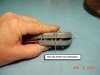
Remove the clear guide and then remove the individual pins necessary to
remove the unwanted cables.
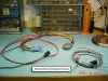
In the lower right had corner of the photo below you can see how much I was
able to remove.
Watch this video to see how you can remove the individual pins from the
main connector.
Decluttering AEM AQ-1 wiring harness for hayabusa
https://www.youtube.com/watch?v=p6b0pei-Ooc
Attachments
mathd
solid fixture here in the forum
Did you figure how to use the 4000 pulses/mile for logging speed?
Am just curious.
I guess you have to convert that to a variable voltage for the datalogger?
You could use the TC9400 IC to do a frequency to voltage converter.
http://pdf.datasheetcatalog.com/datashe ... 21483b.pdf
or the 4017B Decate(pulse) counter IC. but that will be more circuitry.
Am just curious.
I guess you have to convert that to a variable voltage for the datalogger?
You could use the TC9400 IC to do a frequency to voltage converter.
http://pdf.datasheetcatalog.com/datashe ... 21483b.pdf
or the 4017B Decate(pulse) counter IC. but that will be more circuitry.
I won't know until I try and that means the wiring project must be done first. But
for your info, below is the conversation I had at AEM who makes the AQ-1 data
logger. I don't know why, but AEM delated some post of my and his and then
answered my first post again. And he gives me no clues how, just that it can be
done.
Thanks for the suggestion, I will keep the TC9400 IC in mind.
Rick Said:
I have a SpeedHut GPS Speedometer with an ouput that has a square wave of
4000 pulses/mile and 0-5 volts.
Can I measure vehicle speed with an Analog/Freq input or will I have to use a
math channel?
Rick
http://www.speedhut.com/gauges/GPS-Speedometers/1:3
http://www.speedhut.com/instructions.i
AEM Said:
Yes, if you supply a variable frequency 5v square wave to the AQ-1, you can
record vehicle speed.
I suspect what AEM calls a Math Channel might be needed. Once you have the
data, then the software can perform math functions on the data and then display
the massaged data like any other channel.
Below are the math function available:
abs
sin
cos
tan
asin
acos
atan
atan2
sinh
cosh
tanh
asinh
acosh
atanh
pow
exp
ln
log
log2
floor
ceil
frac
sqr
sqrt
int
bool
real
raw
round
degtorad
radtodeg
max
min
sgn
mod
mask
combine
combine8
combine16
combine16_float32
reinterpret_float32
reinterpret_float64
complement
eswap16
eswap32
eswap64
bitrev8
bitrev16
bitrev32
bitrev64
can_decode_le
can_decode_be
avg
avg_nonzero
if
usecs
msecs
seconds
sample_pos
sample_count()
metres_abs
lap
lap_start_seconds
lap_seconds
lap_start_metres
lap_metres
is_lap_start
layer_seconds
layer_metres
integrate
integrate_lap
integrate_add
integrate_sum
derivative
declick
declick_if
prev
at_sample
at_seconds
at_seconds_lerp
filter_lp
filter_hp
filter_bs
filter_bp
filter_gaussian
filter_avg
g_correct_x
g_correct_y
g_correct_z
gps_haversine_metres
gps_haversine_delta
noise
noise_gaussian
layer
mathd
solid fixture here in the forum
Am reading the aq-1 manual right now, look like you can plug it directly to the Analog/Frequency 5-8 inputs
and it seem easy to setup, see page 11
http://aemelectronics.com/files/instruc ... System.pdf
Vehicule speed can be written as VSS or hall effect sensor sometime.
and it seem easy to setup, see page 11
http://aemelectronics.com/files/instruc ... System.pdf
Vehicule speed can be written as VSS or hall effect sensor sometime.
RICK!
YOUV'E GOT AMAZING PHOTOGRAPHIC SKILLS
YOUV'E GOT AMAZING PHOTOGRAPHIC SKILLS
mathd said:Am reading the aq-1 manual right now, look like you can plug it directly to the Analog/Frequency 5-8 inputs
and it seem easy to setup, see page 11
http://aemelectronics.com/files/instruc ... System.pdf
Vehicule speed can be written as VSS or hall effect sensor sometime.
I hope you are right, but sixty years of experience has taught me that it's never that easy!

I believe that was part of my post on the AEM forum, but they deleted that post for some reason.
grumpyvette said:RICK!
YOUV'E GOT AMAZING PHOTOGRAPHIC SKILLS
Thanks Grumpy, but right now I would easily trade the photographic skills for
some amazing electrical skills!
mathd
solid fixture here in the forum
Well its not really hard.
You just need to convert the squarewave to a sinewave (that can be done using some integrator circuit usually 2 of them in serie)
Use that frequency to voltage converter chip = LM2907/LM2917 (this one is better its meant for automotive use)
Then buffer the output(and set the output gain) with a transistor or op-amp since you use them to build the integrator circuit.
I could build all of that on a pcb for you if you really can't get the AEM to read the VSS. But i dont see why it will not work since it has that function build it.
The manual state it can be used for vehicule speed, the hard part will be the calibration. probably lots of math.
And your dealing with squarewave.. this has alot of high frequency content.. needs good wiring or the AEM will not recognize the signal.
You just need to convert the squarewave to a sinewave (that can be done using some integrator circuit usually 2 of them in serie)
Use that frequency to voltage converter chip = LM2907/LM2917 (this one is better its meant for automotive use)
Then buffer the output(and set the output gain) with a transistor or op-amp since you use them to build the integrator circuit.
I could build all of that on a pcb for you if you really can't get the AEM to read the VSS. But i dont see why it will not work since it has that function build it.
The manual state it can be used for vehicule speed, the hard part will be the calibration. probably lots of math
.And your dealing with squarewave.. this has alot of high frequency content.. needs good wiring or the AEM will not recognize the signal.
mathd
solid fixture here in the forum
Rick, only 10 years ago i could barely read a electrical layout and probably not a electrical schematic..
I started y looking at alot of circuit layout, then schematic, and reading on how the component work.. basic electrical circuit design(amplifiers etc).
Am not going to lie and say its easy.. but its not really hard as many are expecting it to be. it just take a load of time.
About the squarewave.. if you have ever read about transmission lines.. you know that high frequency usually need a coax and matched input and output impedance.
So if your using a single wire.. and its a bit too long(inductance???).. you can get distorted waveform or even signal cancellation because of heavy reflection at the end of the cable or because of the inductance of that wire... and electromagnetic interferences, inductive/capacitive coupling.. When working with high frequency is alot more work that simple DC. Should use a short and high quality shielded wire as a minimum. (the shield will have some capacitance, it will help cancell the inductance and also shield the EMI and reduce coupling with nearby component.)
If you use 2 single wire.. twist them tight together it will help ALOT.(just like AC heater into a tube amp)
Even a 1khz squarewave have alot of high frequency component(harmonic).. if you could get a perfect squarewave with a perfect 0.0000(infinite)µS risetime.. you get infinite high frequency component.. but thats in a theorical perfect world. Getting a fast risetime for a squarewave is not really easy.
Looking a squarewave into a oscilloscope look like a single signal.. put it into a spectrum analyser and tada you see alot of different frequency signals(the original signal + harmonics.)
I started y looking at alot of circuit layout, then schematic, and reading on how the component work.. basic electrical circuit design(amplifiers etc).
Am not going to lie and say its easy.. but its not really hard as many are expecting it to be. it just take a load of time.
About the squarewave.. if you have ever read about transmission lines.. you know that high frequency usually need a coax and matched input and output impedance.
So if your using a single wire.. and its a bit too long(inductance???).. you can get distorted waveform or even signal cancellation because of heavy reflection at the end of the cable or because of the inductance of that wire... and electromagnetic interferences, inductive/capacitive coupling.. When working with high frequency is alot more work that simple DC. Should use a short and high quality shielded wire as a minimum. (the shield will have some capacitance, it will help cancell the inductance and also shield the EMI and reduce coupling with nearby component.)
If you use 2 single wire.. twist them tight together it will help ALOT.(just like AC heater into a tube amp)
Even a 1khz squarewave have alot of high frequency component(harmonic).. if you could get a perfect squarewave with a perfect 0.0000(infinite)µS risetime.. you get infinite high frequency component.. but thats in a theorical perfect world. Getting a fast risetime for a squarewave is not really easy
.Looking a squarewave into a oscilloscope look like a single signal.. put it into a spectrum analyser and tada you see alot of different frequency signals(the original signal + harmonics.)